Abstract
Based on a large section drilling and blasting excavation project, the dynamic response characteristics of civil air defense tunnels are analyzed by combining field monitoring and numerical simulation. The dynamic response features include particle vibration velocity, main frequency, displacement, and stress, and the stability criterion of the tunnel is analyzed. A safety criterion model based on the ultimate tensile strength of materials is established. The results show that the frequency of the , , and directions is mainly distributed in 90-140 Hz. The effective stress increases first and then decreases along the axis of the roadway. The stress near the explosion source is large and the relative reduction is also large. By fitting the relationship between blasting vibration velocity and maximum principal stress, the safe vibration velocity criterion based on tensile strength is obtained, and the safe threshold of vibration velocity is 19.62 cm/s. It can be assumed that blasting does not affect the structure.
Highlights
- Effective stress increases first and then decreases along the tunnel axis.
- Stress near the blast source is larger, and its relative reduction is larger.
- Material has not reached the limit state, so the structure is safe.
1. Introduction
Most of the existing studies are carried out based on numerical simulation. Among them, Wang Qiuyi [1] et al. studied the changes in vibration frequency and amplitude in the tunnel and obtained the dynamic response characteristics of the tunnel at different locations. Li Qingsong et al. used finite element numerical analysis to study the change characteristics of the tunnel and analyzed the distribution law of the dynamic response [2]. Liu, N. et al. used numerical methods to simulate the influence of the strength of the lining structure at different positions of the excavated tunnel on the existing tunnel. The results show that when two tunnels are parallel, the blasting vibration has the greatest influence on the side walls of the two tunnels [3]. Wu Boet al. believes that the influence of the cavity zone after the new working face on the lining of the existing tunnel is greater than that of the uncavity zone [4]. Zhu Zhengguo et al. studied the blasting dynamic response and safety range of the three-dimensional cross tunnel [5] and concluded that the peak vibration velocity of particles (PPV) at the arch and arch foot of the existing tunnel is more sensitive and weaker than that of other locations in the ring direction [6]. Through numerical simulation, field monitoring, and theoretical analysis of stress wave propagation, scholars at home and abroad have carried out a lot of research on the influence of new tunnels on adjacent tunnels during tunnel excavation [7]. J. Mandal studied the numerical simulation of a shallow buried tunnel under a surface explosion load [8]. In the study of A. Mottahedi, a soft calculation method is used to establish the over drilling prediction model of the tunnel [9]. S. Mishra studied tunnel blasting and analyzed the stress-strain response of granite at high strain rates [10]. The flow behind a blast wave, propagating in the downstream direction in a hypersonic tunnel, is investigated analytically by H. Mirels [11]. S. Koneshwaran considers the performance of ground blasting tunnels under fluid-structure coupling [12]. However, due to projects and other reasons [13], few scholars have studied the dynamic analysis of civil air defense tunnels in the process of urban subway tunnel excavation [14].
In summary, domestic and foreign scholars have done a lot of work on the influence of new tunnels on adjacent existing tunnels during mine tunnel excavation by using numerical simulation, field monitoring, and stress wave propagation theory analysis, and many conclusions have important reference significance for the research of this project [15]. In the study of blasting seismic wave propagation, the influence of rock mass properties, charge, distance, and elevation on seismic wave propagation is studied, and the change of seismic wave propagation is obtained. At present, many new tunnels have been analyzed for the stability of adjacent tunnels by blasting excavation. However, due to the project and other reasons, few scholars have studied the dynamic analysis of civil air defense tunnels in the process of urban subway tunnel excavation. Therefore, this paper takes advantage of the special working conditions of the project and uses the method of on-site monitoring and numerical simulation to conduct research. This paper studies the dynamic stability of the tunnel under the blasting action, analyzes the comprehensive influence of the tunnel on vibration frequency, vibration amplitude, and vibration dynamic stress, and establishes a safety criterion model based on ultimate tensile strength.
2. Overview of engineering geology
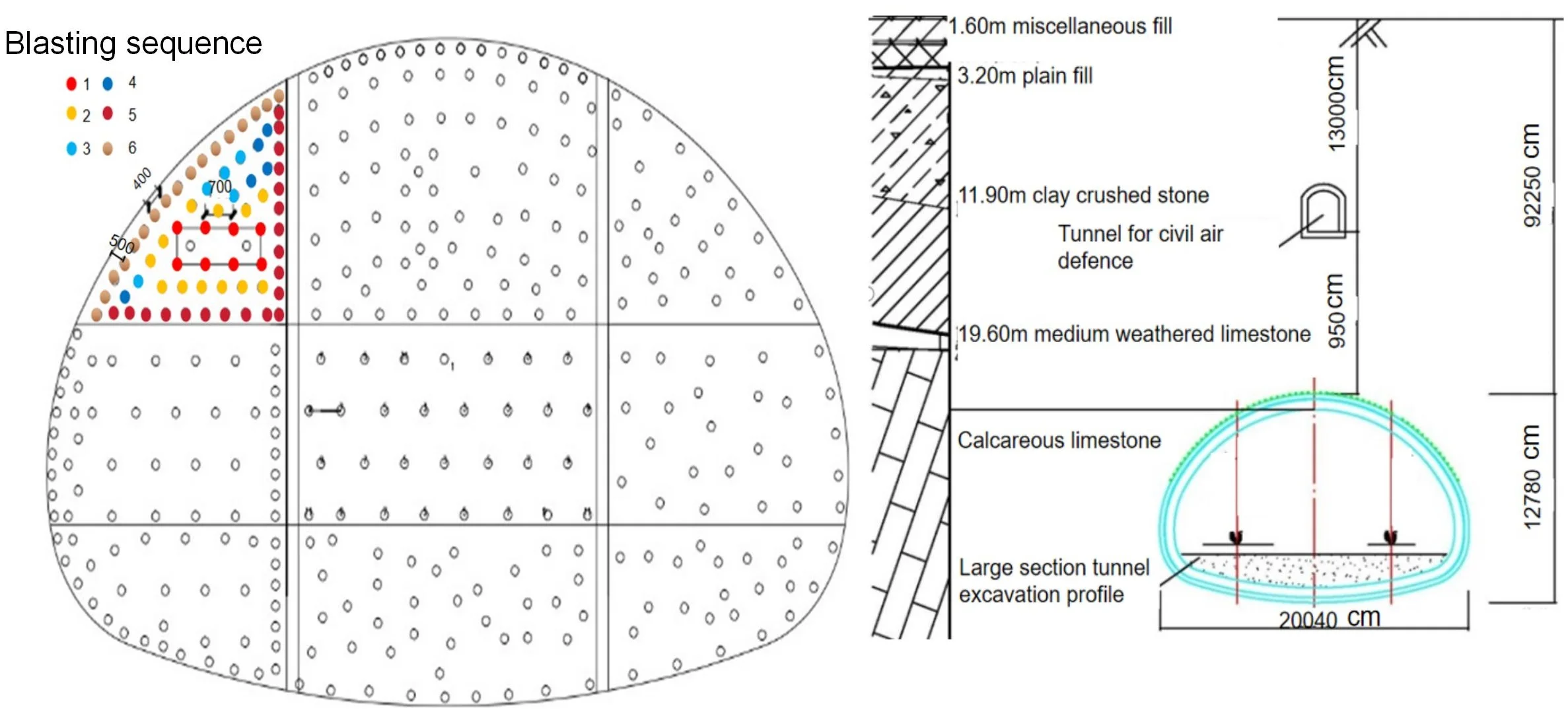
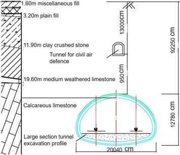
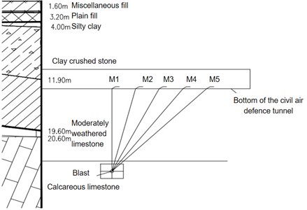
This project is based on the Hong community, which is a double-line tunnel. The large-section tunnel and the civil air defense tunnel intersect under Eighth Road, and their position is shown in Fig. 1. The large-section tunnel is located in the breezed limestone layer, with a partial interpenetration of medium-weathered limestone, with a transverse width of 20.14 m and a midline height of 13.4 m. Within this section, the buried depth of the arch is 22.39-22.94 m, and the spatial position is horizontal. The geological profile of the large-section tunnel and the civil defense tunnel is shown in Fig. 2.
Fig. 1Relationship diagram of the plane position of large section tunnel of civil air defense tunnel
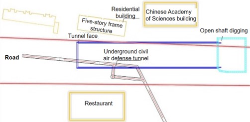
Fig. 2Geological section of large section tunnel and civil air defense tunnel
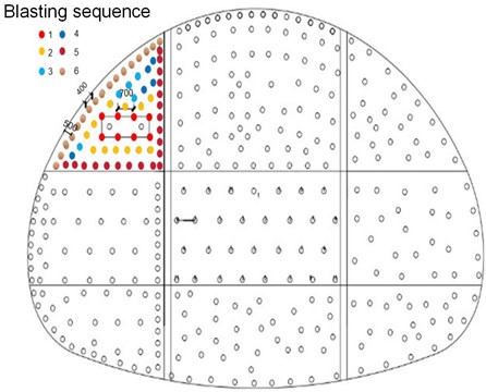
To effectively ensure that the tunnel excavation is not affected by the surrounding structures and the safety of passage, the double-sidewall heading excavation method is adopted in the construction of the large section Ⅲ surrounding rock. According to the double-sidewall diversion excavation technology, the tunnel is divided into three steps, left, middle, and right, with a total of 9 parts. Blasting construction is carried out in sequence, excavation is carried out step by step, and the blasting design adopts the straight-cut method. The peripheral holes are designed according to the requirements of smooth blasting, with hole proximity coefficient 0.8 and minimum resistance line 500 mm. The hole layout is shown in Fig. 3.
Fig. 3Excavation sequence of mine tunnel with large section (Unit: mm)
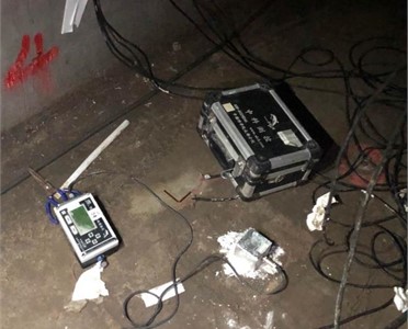
The buildings above the tunnel are dense and there are civil air defense tunnels above the tunnel, blasting vibration monitoring is of great significance for tunnel excavation and protection of future construction (structure). The monitoring diagram is shown in Fig. 4, the monitoring instrument number is TC4850, and a two-hole booster transducer with a frequency of 60 kHz and a minimum peak value of triggered vibration speed of 0.01 cm/s is adopted.
Fig. 4Field monitoring diagram of TC-4850 blasting vibrometer
a) Schematic layout of monitoring
b) Layout of monitoring points
3. Analysis of blasting vibration test results
3.1. Analysis of tunnel vibration characteristics
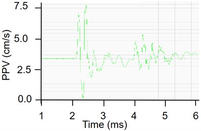
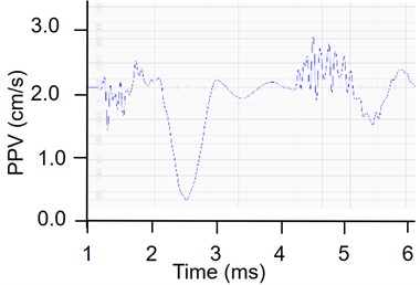
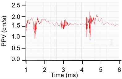
In this paper, the characteristics of vibration intensity are analyzed by using the monitoring data of large-section tunnel excavation. It can be seen from Fig. 5 that the PPV in the direction is in the positive direction, while the PPV in the and direction is in the negative direction. It can be seen from Fig. 5 that the vertical vibration velocity is large, which may be attributed to the following reasons: There is a free surface on the floor of the civil air defense tunnel in the vertical direction, so it has a certain amplification effect on the vibration velocity.
Fig. 5Waveform diagram of PPV in each direction
a) direction
b) direction
c) direction
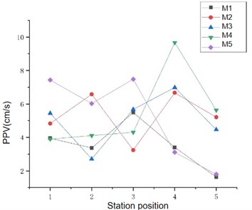
To study the vibration laws in , , and directions, a vibration velocity waveform curve is selected for analysis; According to Fig. 6, it is not difficult to find that the peak time of the vibration tunnel in the direction is 0.015 s, while the peak time in the direction is about 0.25 s, so it is not difficult to find through the Fig. 6.
Fig. 6Statistical diagram of monitoring data at each measuring point
3.2. Attenuation law on the propagation path
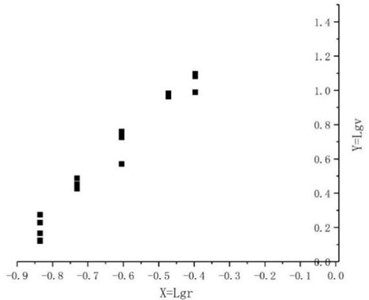
According to the national blasting safety regulations, the Sadowski formula is generally adopted for linear regression analysis, by using the principle of the least square method, the fitting curve can be obtained.
The empirical formula can then be obtained:
where is the peak particle vibration speed, is the amount of explosive, and is the distance from the monitoring point to the explosion source.
Fig. 7Fitting curve of axial blasting vibration velocity of civil air defense tunnel
4. Characteristics and safety criterion of blasting vibration response of civil air defense tunnel
4.1. Numerical modeling
According to the excavation conditions of the project, the tunnel in the large section is 109 meters in total. The upper left guide tunnel is 75 meters excavated, the middle left guide tunnel is 66.5 meters excavated, and the lower left guide tunnel is only 9 meters excavated. Under actual conditions, the axis of the civil defense tunnel has a certain intersection with the axis of the large section tunnel. To reduce the difficulty of modeling, the position of the civil defense tunnel is adjusted to be parallel to the central axis of the tunnel.
Fig. 8Numerical model (1 – plain filled soil, 2 – clay layer, 3 – moderately weathered limestone, 4 – civil defense tunnel, 5 – excavation section unit mm)
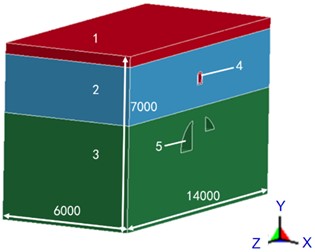
a) Numerical model size
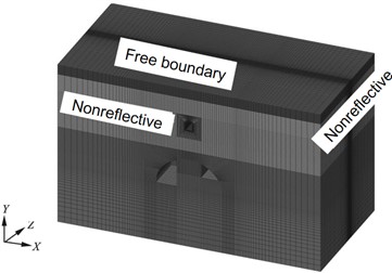
b) Numerical model with grid
According to the field blasting situation, the thickness of the model is 60 meters, that is, the height × width × depth = 70×140×60. The model adopts a cm-g-us unit system, and the unit type is set to SOLID164. The top surface (i.e. the ground) of the model is free, and the remaining five faces are set to non-reflective boundaries.
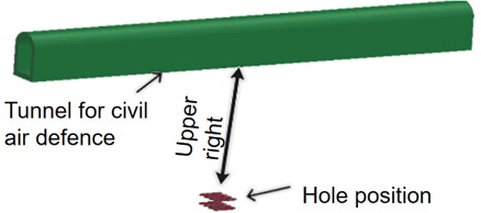
The numerical model is shown in Fig. 8, The vertical direction is the direction, the direction is the axis direction of the civil air defense tunnel, and the direction is the radial direction of the civil air defense tunnel. The model is divided into 904,154 elements. structure diagram of the civil air defense tunnel is shown in Fig. 9, space position diagram of the tunnel and gun hole is shown in Fig. 10.
Fig. 9Structure diagram of civil air defense tunnel

Fig. 10Space position diagram of the tunnel and gun hole
4.2. Material parameters
The tunnel size in the numerical model is consistent with the actual excavation face when the model is built. According to the above knowledge, the mining is divided into 9 parts, and the grid is encrypted in the mining section. To simplify the calculation model, the rock and soil layers are simplified into 3 layers because the strata are mostly uneven and mixed with each other. The specific parameters of rock and soil mass are shown in Table 1.
Table 1Physical and mechanical parameters of rock and soil mass
Names of rocks | Thickness (m) | Density (kg/m3) | Modulus of elasticity (GPA) | Poisson’s ratio | Yield stress (GPA) | Tangential modulus (GPA) | Hardening coefficient |
Breezy limestone | 45.2 | 2.68 | 7 | 0.13 | 15 | 0.21 | 0.5 |
Soil layer names | Thickness (m) | Density (kg/m3) | Shear modulus (MPa) | Poisson’s ratio | Damage surface shape parameters | Friction angle (rad) | Cohesion (kph) |
Plain fill soil | 2.4 | 1.98 | 9 | 0.35 | 0.8 | 0.314 | 0.1 |
Clay | 12.4 | 1.99 | 50 | 0.275 | 0.8 | 0.188 | 0.25 |
The civil air defense tunnel is the main research object, and its lithology condition is mainly clay, and the material parameters are known from the above. According to the data, the concrete used in the civil air defense tunnel is c30 concrete. Due to its long construction time and certain aging strength, the strength, elastic modulus and other parameters of the concrete lining of the tunnel have been reduced to a certain extent. According to the model and experience, it has been weakened to a certain extent.
4.3. Loading mode
Blasting and load is indeed the basis of numerical simulation of explosive dynamic analysis, ANSYS/LS-DYNA numerical simulation software for blasting vibration simulation analysis has strong practicability. However, there are no explosive model parameters in the software, so there are usually two ways to determine the change process of explosive load in the general analysis process: one is to establish the explosive initiation model. The second is the equivalent load applied by half theoretical and half empirical formulas. In this simulation, an explosive initiation model for blasting simulation is established using the first method. The explosive initiation position is reserved when the model is established, and the explosive detonation model is established to simulate blasting during calculation. Since a state equation must be added to the explosion of high explosives, *MAT_HIGH_EXPLOSIVE_BURN high explosives materials and *EOS_JWL equation of state were added during calculation, and the detonation location was set according to the size of the model, so the blasting process was simulated. The explosive model data are shown in Table 2.
Table 2Explosive material parameters
Blasting parameters | Density kg/m3 | Detonation speed | Burst pressure (GPa) |
1.15 | 0.35 | 3.24 |
4.4. Numerical model validation
When using the numerical simulation method to analyze the dynamic response of blasting, to ensure the correctness of the model, the comparison should be made to verify whether the results of numerical modeling simulation are roughly the same as the actual monitoring data.
The reasons for the error may be as follows: (1) the specific parameters of the rock and soil layer cannot be accurately determined, which can be adjusted according to the trial-and-error method in the model calculation, and the principle of orthogonal test is used to determine the accurate blasting parameters; (2) the explosion pressure and other parameters are different from the field monitoring, resulting in partial errors in the vibration propagation time and duration.
To ensure the accuracy of the model, several corresponding points are selected for data comparison, and the obtained data are shown in Table 3. These data are obtained at the frequency of 90-150 Hz, which is obtained by field monitoring. As you can see, the error is less than 25 %. The numerical simulation data and the monitoring data have similar rules of cavitation effect, and the results are all within the allowable error range.
4.5. Analysis of dynamic response characteristics of civil air defense tunnel blasting
When the blasting seismic wave propagates in the rock and soil layer, the PPV of the blasting seismic wave propagates in different media and different structures will be greatly different. If there are buildings (structures) in the propagation range of the wave, it will cause the displacement and stress change of the building structure particles, and sometimes it may cause structural instability. To fully grasp the strength and characteristics of structural particle vibration velocity, stress, and displacement change, a more detailed study should be carried out according to the characteristics of the building structure. This paper is about an underground structure - an air defense tunnel. When studying the dynamic response of air defense tunnel lining structure and surrounding rock under blasting vibration, the stress distribution law of radial, tangential, and vertical units should be analyzed. The above analysis shows that in theory, the vertical response should be the largest in the analysis of radial tangential and vertical vibration responses. In the field monitoring, the velocities of five points were measured in the radial direction. To study the response characteristics of the three directions, five measuring points were also set by numerical simulation to obtain the time-history curves of horizontal radial, horizontal tangential, and vertical vibration velocities, as shown in Fig. 11.
Table 3Comparison between numerical simulation and field monitoring data
Data Type | Monitoring point bits | Horizontal tangential vibration velocity (cm/s) | Horizontal radial vibration velocity (cm/s) | Vertical vibration velocity (cm/s) | Peak frequency (Hz) |
Field monitoring data | 1 | 2.674 | 2.45 | 7.43 | 94 |
2 | 2.43 | 2.34 | 7.63 | 102 | |
3 | 1.10 | 1.73 | 4.025 | 132 | |
4 | 0.652 | 0.64 | 1.79 | 112 | |
Numerical simulation data | 1 | 3.28 | 2.28 | 8.19 | 105 |
2 | 1.79 | 2.03 | 9.14 | 116 | |
3 | 0.68 | 1.41 | 3.68 | 125 | |
4 | 0.356 | 0.733 | 1.166 | 120 |
Fig. 11Distribution diagram of the three-way PPV
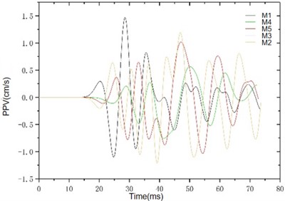
a) The radial vibration waveform diagram
b) Tangential vibration waveform diagram
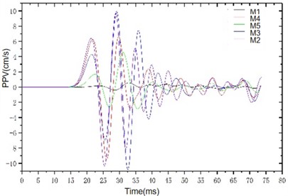
c) Vertical vibration waveform diagram
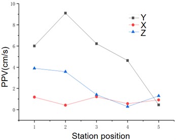
d) Axial trend diagram of the three-way PPV
It can be seen from Fig. 12 that the overall magnitude of the PPV in the three directions is vertical > horizontal radial > horizontal tangential. It can be seen from the attenuation of vibration velocity in the three directions: Within the same propagation distance, the variation range of vertical vibration velocity is 9 cm/s-0.45 cm/s, and the attenuation range of horizontal radial and horizontal tangential is roughly 3 cm/s-0.289 cm/s, which indicates that the vertical vibration velocity decays faster along the tunnel axis and the variation range is larger. When the distance between the vertical vibration velocity and the horizontal vibration velocity is smaller than the distance between the detonation centers, the difference in the peak value is obvious. Similar to the actual monitoring data, the vertical vibration velocity increases first and then decreases along the tunnel axis, indicating that there is an obvious vertical cavitation effect, which verifies the correctness of the law presented by the actual monitoring data.
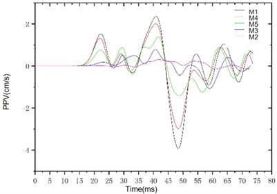
In the study of the dynamic response of rock lining under blasting vibration, stress, and displacement are very important parameters. According to the arrangement of on-site monitoring and measuring points, a consistent measuring point is selected in the numerical model to study the stress. Concrete is not an ordinary solid, but a porous medium, the material structure is more complex, there are many pores developed inside, the pores are also saturated with fluid, and the fluid has a certain pressure. Concrete is subjected not only to external pressure but also to internal pressure (pore pressure). Concrete compresses when subjected to external pressure. Concrete expands when subjected to internal pressure. Therefore, when studying the deformation of concrete, it is necessary to deduct the role of internal pressure from the external pressure, after which the so-called effective stress is defined. The positive of effective stress in this study is tensile stress, and the negative is compressive stress. Because the change of force will cause structural deformation or even instability failure, the interface is selected at the point where the stress is maximally distributed along the axis for deformation analysis, as shown in Fig. 12.
Fig. 12Waveform of stress
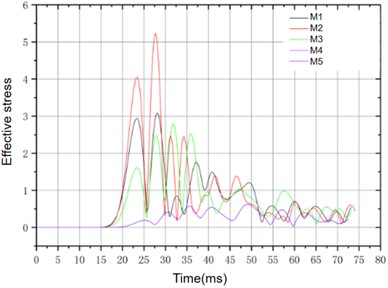
a) Time history curve of effective stress
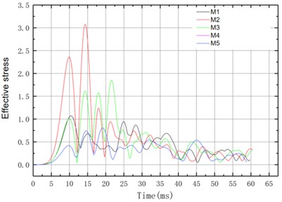
b) Shear stress time history curve
It can be seen from Fig. 12 that the effective stress increases first and then decreases along the tunnel axis. The stress near the explosion source is larger, and its relative reduction is larger. In the tunnel, the effective stress and shear stress are not large, and the material has not reached the limit state, so the structure is safe. According to engineering experience, the compressive strength of the rock is much greater than the tensile strength, so the damage of the rock is generally tensile failure. According to the ultimate failure criterion, whether the rock mass is damaged mainly depends on whether the tensile stress reaches the ultimate tensile strength. Because the stress in ANSYS/LS-DYNA software follows the principle of “tensile stress is positive compressive stress is negative”, it can be seen from the stress time-history curve that the maximum principal stress is tensile, all of which are less than 0.4 MPa, and the ultimate tensile strength of the lining structure is about 1.78 MPa, so the structure is not damaged.
4.6. Instability mode and safety criterion of the tunnel structure
It can be seen from the above that the damage to tunnel lining structure should be tensile. To ensure the construction safety, the common method is to control the blasting process and reduce the impact of blasting on the structure. At present, there are two commonly used methods: (1) numerical simulation to fit the relationship between stress and vibration velocity; (2) using elastic stress wave propagation theory.
In this paper, method (2) is used to fit the relationship between stress and vibration velocity based on numerical simulation to establish a safety criterion model of blasting vibration velocity of tunnel lining structure. The PPV is linearly fitted with the maximum principal stress of the corresponding unit at the monitoring point of the tunnel floor. By fitting the relationship between the blasting vibration velocity and the maximum principal stress on the lining of the civil defense tunnel, the relationship between the maximum vibration velocity and the tensile stress of the civil defense tunnel is obtained. The regression analysis equation is as follows:
where: ; is the tensile stress, is maximum vibration velocity.
Under the action of blasting vibration, the ultimate tensile strength of the concrete lining structure will be increased in the dynamic response process, and the degree of its tensile strength improvement under the dynamic action is related to the application speed of the load. The static tensile strength and dynamic tensile strength are related as follows:
where: is dynamic tensile strength of C30 concrete, is static tensile strength of C30 concrete; is load rate, , is arbitrary loading speed, is loading speed; is dynamic strength improvement coefficient.
Considering the premature construction time of the civil air defense tunnel and the aging effect of the lining material, the strength of the original concrete is reduced to a certain extent. According to experience, the improvement coefficient of dynamic tensile strength is between 1.24 and 1.48, and 1.35 is taken here. Based on engineering experience, the tensile strength of concrete is 1.78 MPa, so the dynamic tensile strength should be 2.403, and the critical vibration velocity of blasting is 19.62 cm/s.
5. Conclusions
With the increase of detonation distance, PPV gradually decreases, and the maximum PPV appears above the detonation source. Based on the analysis of the attenuation law of vibration velocity in the excavated area, it is found that the section size of the excavated cavity and the distance between the blasting center have a great influence on the attenuation rate of blasting vibration velocity.
The frequency distribution of blasting the main shock wave in , , and directions is different, and the main frequency distribution interval is between 100-140 Hz. The stress near the explosion source is large and the relative reduction is also large.
By fitting the relationship between blasting vibration velocity and maximum principal stress, the criterion of safe vibration velocity based on tensile strength is obtained, and the safe threshold of vibration velocity is 19.62 cm/s, which can be considered that the blasting does not influence the structure.
This paper mainly studies the stability of civil defense tunnels under blasting action based on field tests and numerical simulation and is limited to many aspects of theoretical research. Therefore, more theoretical research ideas should be added in future research.
References
-
C. Shi, Y. Zhao, C. Zhao, Y. Lou, X. Sun, and X. Zheng, “Water-sealed blasting control measures of the metro station undercrossing existing structures in ultra-close distances: a case study,” Frontiers in Earth Science, Vol. 10, pp. 450–458, Mar. 2022, https://doi.org/10.3389/feart.2022.848913
-
Q. S. Li, Z. L. Tian, C. S. Wang, K. Xu, and J. H. Xie, “Analysis of dynamic influence of new tunnel blasting Construction on existing rail transit section tunnels,” Journal of Building Construction, Vol. 42, No. 3, pp. 454–457, 2020.
-
N. Liu, P. Zhang, K. Li, and Y. Q. Yu, “Massively parallel numerical simulation of 3D shock wave propagation based on JASMIN framework,” Journal of Physics: Conference Series, Vol. 2478, No. 2, p. 022022, Jun. 2023, https://doi.org/10.1088/1742-6596/2478/2/022022
-
B. W. Hu, Z. Z. Chen, and Y. B. Liu, “Study on Impact of tunnel blasting vibration on safety of adjacent buildings,” Highway, Vol. 3, pp. 232–234, 2012.
-
B. Wu, Y. B. Lan, and J. X. Yang, “Study on Effect of blasting in new tunnel on vibration characteristics of adjacent tunnel,” China Safety Science Journal, Vol. 29, No. 11, pp. 89–95, 2019.
-
Y. Fan, “Analysis of influence of newly built tunnel excavation on existing tunnel structure with small clear distance,” Fujian Building Materials, Vol. 6, pp. 4–6, 2019.
-
Z. S. Wu, Pp. S. Chen, and W. Wang, “Influence and safety criterion of expansion tunnel blasting on existing lining,” Water Resources and Hydropower Technology, Vol. 51, No. 5, pp. 77–85, 2019.
-
J. Mandal, A. K. Agarwal, and M. D. Goel, “Numerical modeling of shallow buried tunnel subject to surface blast loading,” Journal of Performance of Constructed Facilities, Vol. 34, No. 6, pp. 1–14, 2020.
-
A. Mottahedi, F. Sereshki, and M. Ataei, “Development of overbreak prediction models in drill and blast tunneling using soft computing methods,” Engineering with Computers, Vol. 34, No. 1, pp. 45–58, Apr. 2017, https://doi.org/10.1007/s00366-017-0520-3
-
S. Mishra and T. Chakraborty, “Determination of high-strain-rate stress-strain response of granite for blast analysis of tunnels,” Journal of Engineering Mechanics, Vol. 8, pp. 81–145, 2019.
-
H. Mirels and J. F. Mullen, “Aerodynamic blast simulation in hypersonic tunnels,” AIAA Journal, Vol. 3, No. 11, pp. 2103–2108, Nov. 1965, https://doi.org/10.2514/3.3321
-
S. Koneshwaran, D. Pp. Thambiratnam, and C. Gallage, “Performance of buried tunnels subjected to surface blast incorporating fluid-structure interaction,” Journal of Performance of Constructed Facilities, Vol. 29, No. 1, pp. 1–21, 2021.
-
C. Pany et al., “On the bursting of an HSLA steel rocket motor case during proof pressure testing,” Steel Grips (Journal of Steel and related Materials) Application, Vol. 10, pp. 434–438, 2012.
-
M. G. Sreelakshmi and C. Pany, “Stress analysis of metallic pressure vessels with circumferential mismatch using finite element method,” International Journal of Science and Engineering Research, Vol. 7, No. 4, pp. 479–484, 2016.
-
H. G. Ni, Z. L. Pan, K. Sun, and Y. L. Zhang, “Field measurement and numerical simulation of dynamic response of masonry structure under ground motion of blasting,” Building Structures, Vol. 50, pp. 122–126, 2003.
-
C. H. Zhang, “Vibration velocity threshold analysis of existing tunnel lining caused by adjacent tunnel blasting construction,” Building Structures, Vol. 2, pp. 1–20, 2009.
About this article

The study was sponsored by the National Natural Science Foundation of China (Grant No. 52308393).
The datasets generated during and/or analyzed during the current study are available from the corresponding author on reasonable request.
Conceptualization, Li Yaoxin,Wang Zhibin, Qiqi Luo, Tingyao Wu, methodology, Li Yaoxin, Tingyao Wu; software, Li Yaoxin; validation, Wang Zhibin; writing-original draft preparation, Wang Zhibin ,Tingyao Wu; writing- review and editing, Tingyao Wu; project administration, Tingyao Wu; funding acquisition, Tingyao Wu.
The authors declare that they have no conflict of interest.
