Abstract
Seismic waves created during explosions are transmitted in an outward direction via the surrounding medium, creating a seismic effect that compromises the security of facilities. The energy released during explosions forms dynamic pressure, which creates gas pressure-induced blast waves that cause the ground to vibrate. The damage extent and influence of a blast are dependent on the energy released by the blast shock waves. Blast waves influence the stability of materials. Therefore, controlling vibration hazards is imperative in ensuring material security. This study investigated the effect of explosion-induced vibrations on the surface of a leveled landform. Changes in dynamic load over time were analyzed by conducting numerical simulations and actual onsite experiments. The Multi-Material Arbitrary Lagrangian-Eulerian algorithm were employed to develop a structural model for coupling fluid with solid grids, which was used to analyze the ground acceleration induced by the blasting effect. The results were used to determine the appropriate distance from which vibration reduction, disaster prevention, and safety protection can be achieved.
1. Introduction
The term blasting effect refers to the seismic effect experienced in a particular region after the detonation of dynamite. Explosions are characterized by short load time, high-frequency vibrations, and high material, geometric, and status nonlinearity. Explosion energies are diffused rapidly to surrounding areas in the form of waves. They induce a seismic effect leading to nuclide vibrations on the ground surface. Analyzing and controlling vibration hazards from explosions before designing and implementing structures is imperative. Dynamite buried near the ground surface, under the ground surface, or deep into the ground generates shock waves in the soil when detonated, affecting material stability. Blast waves produced from explosions are highly nonlinear. Blast waves are primarily triggered by shock waves and subsequently change into elastic seismic waves, causing the vibration of nuclides at the ground surface [1]. Shock waves inherently exhibit high speeds and pressure. Therefore, the characteristics of shock waves and the vibration intensity of the ground surface are typically used in the analysis of the degree of vibration-induced damage [2, 3].
Soil is a nonhomogeneous and anisotropic material. Its properties influence the safety of ground surfaces and underground engineering projects. A ground surface or near-ground-surface explosion creates stress waves that are transmitted through soil; the magnitudes of such stress waves are dependent on soil properties, soil strength, and their proximity to the explosion location. Detonation waves are transmitted to structures through soil, with soil properties affecting the structures’ dynamic responses; likewise, the mechanical behavior of soil is affected by the structures. This is referred to as the soil-structure interaction effect.
Soil-structure interaction analyses are markedly complex. To prevent strong earthquakes from jeopardizing structural safety, antiseismic designs focus on dissipating the energies created during earthquakes. Accordingly, identifying the means of accurately analyzing the geological characteristics of a location and providing the correct key parameters to elevate the seismic base isolation effect are crucial factors in the study of seismic wave transmission. Oldrich [4] explored the properties of surface waves induced by earthquakes, and Vinh, Pham, and Ogden [5] provided referential information related to engineering applications by analyzing the development trends of Rayleigh wave speeds in elastic solids. Stoneley [6] analyzed surface wave transmission in elastic media with orthorhombic symmetry; the results showed that the changes in the speeds of the body waves and surface waves were greater than those obtained in earthquake surveys. Eskandari et al. [7] examined the dynamic responses of rigid circular bases in transversely isotropic half-spaces and presented elastic zone-related problems in the form of semi-infinite line integrals. Ahmadi and Eskandari [8] performed a vibration analysis of transversely isotropic materials that had been embedded with hard circular disc-like objects, explored the effects of anisotropic materials, and verified their results in an isotropic full-space. Eskandari et al. [9] investigated the axisymmetric time-harmonic response of a surface-stiffened transversely isotropic half-space, focusing on the buried time-harmonic normal load, and verified the accuracy of their results for surface loading, static loading, and isotropic material calculation. Dowding [10] monitored and controlled explosion vibrations by using an earthquake engineering design and explained the mechanisms through which vibrations created wall cracks in the structures. Pal Roy [11] analyzed the ground vibrations and responses of different structures during underground and ground surface blasts, with their results demonstrating that ground surface vibration frequencies were very low (5-35 Hz) and that ground surface structural vibration increased as structural height increased. Singh and Roy [12] studied the damages sustained by ground surface structures during blasts in underground coal mines, showing that ground surface structural vibrations decreased significantly (45 %) as structure height increased.
This study mainly assessed the safe quantity distance during a blast. The ground surface soil properties obtained from an onsite explosion experiment were measured and vibration reduction measures were proposed. The data may be used to determine soil properties after a blast, analyze the dynamic responses of structures after a blast, and explore the effects of soil-structure interaction. Accordingly, the data may serve as a reference when designing antiblast engineering projects.
Because blast waves induce the vibration of the surrounding medium at the ground surface, conducting explosion experiments is dangerous. To study detonation-related parameters, international scholars typically use LS-DYNA as a research tool, adopt energy conversion-related perspectives, and refer to mass, energy, and conservation of momentum-related theories. Crandle [13] analyzed the transfer characteristics of blast waves and determined that seismic waves are transmitted outward through the surrounding medium, creating ground vibration. Kivity et al. [14] simulated and analyzed ammunition depot explosions and observed that relative error between the maximum detonation pressures created by actual dynamite and those obtained from experiments was within 15 %. Hung [15] analyzed C4-dynamite based free field explosions and compared the study results with antidetonation TM5-855-1 [16] guidelines, reporting that the relative error associated with a scale distance of 2-2.37 was 5 %. Wang [17] studied the shock wave energy from free field explosions and determined that the relative error of the detonation pressure was higher for locations within 200 cm of the explosion source and that this error decreased as the transfer distance increased. This result verified the effectiveness of finite element software LS-DYNA in analyzing blast wave transfer behavior.
The current study analyzed the effect of explosion-induced vibrations on the surface. The dynamic response of the ground surface was analyzed by conducting explosion experiments and using finite element software. To understand how to efficiently control vibrations during explosions, the attenuation characteristics of blast waves during blast wave transmission was examined. The examination results provided information about shock wave energy during explosions and can be used to estimate the degree of impact that will be sustained by targets, enabling engineers to adopt related vibration-reduction measures.
2. Ground explosion experiment
Fig. 1 depicts the actual onsite setup. A triaxial acceleration device was used to measure the ground acceleration, and a signal regulator was combined with an oscilloscope to transmit signals. This study analyzed ground acceleration induced by explosions by applying an explosion experiment and numerical simulation. For the explosion experiment, 0.25 lb (113.389 g) of TNT was placed upright on the ground, and this position served as the explosion source. The horizontal and vertical ground acceleration of locations 300, 400, 500, 600 and 700 cm away from the explosion source were measured.
Because ground surface accelerations were measured using the oscilloscope, which collected ground surface acceleration signals, the trigger voltage and delay in signal reception were repeatedly adjusted to prevent distance changes from affecting the accuracy of the measurement results.
Fig. 1Onsite setup for the explosion experiment
3. Numerical simulation analysis
3.1. Finite element calculation
This study applied LS-DYNA procedure and Multi-Material Arbitrary Lagrangian-Eulerian (MMALE) to analyze the contact-explosion-induced seismic effect on the ground surface. The Eulerian algorithm is a spatial coordinate-based method. Because grids and materials to be analyzed in this algorithm are independent, calculations can be executed even if severe spatial distortions occur. However, the disadvantage to this algorithm is the difficulty in measuring the physical quantity of grid materials. The Lagrangian algorithm is a material coordinate-based algorithm that can effectively analyze the time history of nuclides. Nonetheless, the disadvantage to this algorithm is that the grids are severely distorted when considerable displacements and deformations occur, and such distortions lead to program termination. The MMALE algorithm, which combines the advantages of the Lagrangian and Eulerian algorithms, effectively tracks the motion history of nuclides. This algorithm is thus favorable for real-time motion analysis [18, 19]. Because algorithms applied for calculations must be paired with the corresponding element types, the MMALE algorithm was paired with three-dimensional, eight-node-type solid elements in the current study. The equations used in the evaluations are listed as follows: Eqs. (1) and (2) represent the conditions applied to ensure the stability of the solid elements. Eq. (3) shows the characteristic length. Eq. (4) represents the transmission speed of the waves emitted by the elastic materials with fixed volume modulus:
where is the characteristic length; is the sonic velocity in materials; is the function of volume viscosity coefficients and ; is the strain rate tensor; is the element volume; is the area at the longest side; is Young’s modulus; is Poisson’s ratio; is the mass density.
LS-DYNA was used to conduct explicit time integration, an operation involving the use of the minimum time step () of elements. Eqs. (5), (6), (7) were subsequently used to calculate the nodes’ acceleration, speed, and displacement matrices, respectively. The time step method is a conditional method for calculating stability; according to a relevant instruction manual, the control coefficient used to analyze explosions must be less than 0.67 [20, 21]:
where represents the acceleration matrix for a node at time ; is the velocity matrix for a node at time ; denotes the mass matrix; refers to the external force matrix; is the sum of internal and contact forces on the element; represents the damping matrix; is the hourglass resistance force.
3.2. Numerical analysis model
Fig. 2 shows the 1/4 symmetric numerical analysis model. The size of the rectangular TNT, 6.56×3.2×89.3 cm; weight of the 0.25 lb (113.389 g). On the basis of the relevant research reveal [22, 23] conducted using the numerical analytical method. This study applied the MMALE algorithm to analyze the effects of contact explosion induced vibrations on the surface of a leveled landform. The air and dynamite were defined as Eulerian grids and the soil used was defined as a Lagrangian grid. The fluid and solid grids were mutually independent, and a numerical model was created by coupling the fluid with solid grids, in which the two grids were overlapped [24]. For the conditions for the explosion experiment, the MMALE algorithm was employed and a 3D eight-node solid element was used to develop a 1/4 symmetric numerical analysis model that analyzed the ground acceleration induced by the blasting effect as well as changes in ground acceleration over time and at different locations. The minimum width of the TNT was set as the grid density, and 1/4 of the length of the shortest side of the dynamite was set as the size of the fluid grids. The grid size for air, dynamite, and soil was set to 1.64, 1.64 and 3.28 cm, respectively, and the time step control coefficient was defined as 0.3.
Table 1 shows the soil, air and TNT parameters. The blasting effect analysis was combined with the appropriate equation of state to describe the volume, stress, and strain of materials. To analyze air behavior, MAT_NULL was paired with an equation of state called EOS_LINEAR_POLYNOMIAL Eq. (8) [18]. To analyze material behavior, the dynamite was expressed in the form of MAT_HIGH_EXPLOSIVE_BURN and paired with an equation of state called Jones-Wilkins-Lee Eq. (9) [25]. The related parameters used in this study were derived by referring to the explosive handbook published by the Lawrence Livermore National Laboratory [26]. Subsequently, the stress transfer behavior from the explosions was analyzed using soil properties described using the MAT_SOIL_AND_FOAM model [18, 25]. The soil from the explosion was analyzed using the unified soil classification system. The results revealed that the soil was low-grade sandy soil containing silt. This soil was classified as SP-SM. In the Table 1, RO is the mass density; PC is the pressure cutoff; MU is the dynamic viscosity coefficient; TEROD is the relative volume for erosion in tension; CEROD is the relative volume for erosion in compression; YM is the Young’s modulus; PR is the Poisson’s ratio; is the initial internal energy per unit reference specific volume; is the initial relative volume; is the detonation velocity; PCJ is the chapman-Jouget pressure; BETA is the beta burn flag; is the bulk modulus; is the shear modulus; SIGY is the yield stress:
where is the pressure; , , , , , , are constants; is the dynamic viscosity coefficient, ; is the initial energy per unit volume; is the relative volume; , , , and are the constants for dynamite characteristics.
Fig. 21/4 symmetric numerical analysis model
Table 1Parameters for soil, air and TNT explosive
Element | Material and equation of state parameters (unit system: g, cm, -second) | ||||||
Soil | MAT_SOIL_AND_FOAM | ||||||
RO | BULK | ||||||
1.871 | 0.000147 | 0.00729 | 2.116E-12 | 6.68E-12 | 5.28E-12 | 0.0 | |
Air | MAT_NULL | ||||||
RO | PC | MU | TEROD | CEROD | YM | PR | |
0.00129 | 0.0 | 0.0 | 0.0 | 0.0 | 0.0 | 0.0 | |
EOS_LINEAR_POLYNOMIAL | |||||||
, , , | |||||||
–1.07E-06 | 0.0 | 0.4 | 0.4 | 1.0 | 2.53-06 | ||
TNT | MAT_HIGH_EXPLOSIVE_BURN | ||||||
RO | PCJ | BETA | SIGY | ||||
1.63 | 0.693 | 0.21 | 0.0 | 0.0 | 0.0 | 0.0 | |
EOS_JWL | |||||||
OMEGA | |||||||
3.712 | 0.03231 | 4.15 | 0.95 | 0.3 | 0.07 | 1.0 | |
4. Results and discussion
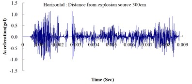
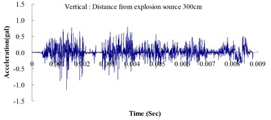
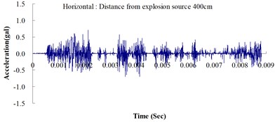
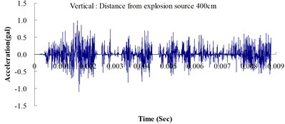
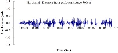
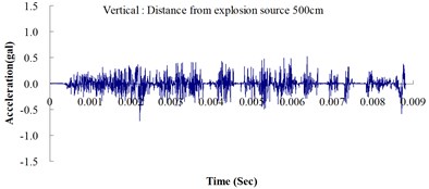
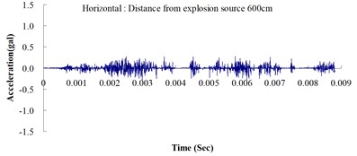
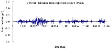
Table 2 shows the maximum horizontal and vertical ground accelerations obtained from the numerical analysis and the experiment. These ground accelerations were measured from locations 300, 400, 500, 600 and 700 cm away from the explosion source. Fig. 3 shows the ground acceleration curve over time from the explosion experiment.
Fig. 4 illustrates the numerical analysis results detailing the ground acceleration curve over time. The leveled landform explosion experiment was conducted to measure the physical quantity of ground acceleration induced by vibrations from explosions and to analyze the transfer characteristics of the blast waves.
Fig. 3Ground acceleration curve over time from the explosion experiment
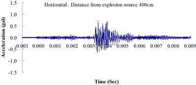
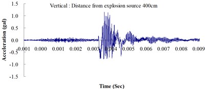
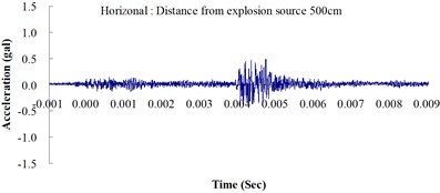
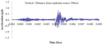
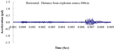
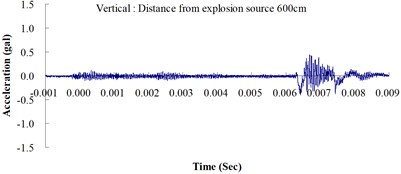
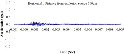
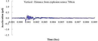
The results of this experiment indicated that the vertical ground acceleration was greater than the horizontal ground acceleration and that the ground acceleration decreased as the distance from the explosion source increased. As the distance from the explosion source exceeded 500 cm, the magnitude of the shock wave attenuation decreased considerably, and the rate of decrease in horizontal ground acceleration was greater than that in the vertical ground acceleration. The overall ground deceleration trend was consistent with the energy attenuation characteristics of blast waves. Ground vibration effect was classified according to the acceleration values corresponding to the degree of ground vibration; specifically, a value of 0.8 gal or lower was assigned for no vibrations and a value of 0.8-2.5 gal was assigned for minimal vibrations. The degree of vibration experienced within 500 cm from the explosion source was characterized as Level 1, in which a person at rest could feel small vibrations.
Fig. 4Numerical analysis of the ground acceleration over time
The ground acceleration derived from the explosion experiment was compared with that from the numerical analysis to verify the accuracy and feasibility of the numerical analysis. The relative error of the numerical analysis (measured in percentages) was calculated as follows: (simulated ground acceleration – experimental ground acceleration) / experimental ground acceleration 100 %. The calculations showed that the relative errors for the simulated horizontal and vertical ground accelerations were within the 15 % acceptable range, meeting the standards reported in the literature [14]. The analysis results revealed that the ground acceleration decreased as the distance from the explosion source increased. These results confirmed the effectiveness of the numerical model developed in this study by using the MMALE algorithm, and the 3D eight-node solid element in analyzing the transfer characteristics of shock waves as well as the dynamic response of ground surfaces following explosions.
Table 2Maximum ground acceleration from both the explosion experiment and the numerical analysis
Distance from explosion source (cm) | Experiment (gal) | Numerical analysis (gal) | Relative error (%) | |||
Horizontal | Vertical | Horizontal | Vertical | Horizontal | Vertical | |
300 | 1.215 | 1.206 | 1.121 | 1.149 | –7.737 | –4.726 |
400 | 0.750 | 1.167 | 0.700 | 1.090 | –6.667 | –6.598 |
500 | 0.484 | 0.806 | 0.430 | 0.721 | –11.157 | –10.546 |
600 | 0.326 | 0.463 | 0.290 | 0.410 | –11.043 | –11.447 |
700 | 0.188 | 0.340 | 0.170 | 0.311 | –9.575 | –8.529 |
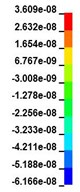
Fig. 5Time history of acceleration from the soil medium
a) 1029 μs
b) 2,500 μs
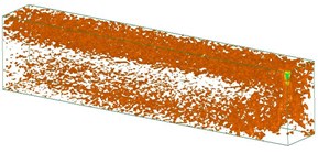
c) 5,558 μs
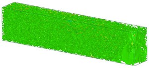
d) 10,009 μs
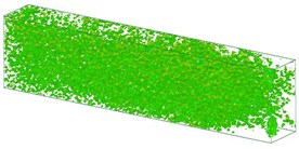
e) 12,508 μs
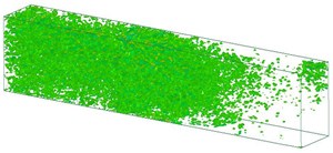
f) 15,000 μs
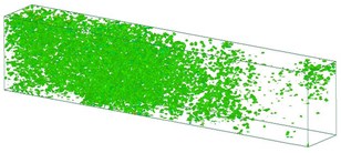
g)17,500 μs
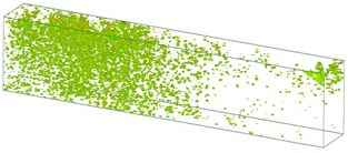
h)19,919 μs
Fig. 5 shows the changes of acceleration in the soil medium. Shock waves are a type of strong compression wave. Explosions create high-temperature, high-pressure gas that compresses the surrounding environment, and the corresponding shock waves are transmitted via the surrounding medium. Compression waves are formed as explosions are attenuated. Most of the energies from the explosions are consumed by the surrounding medium, which undergoes deformation and destruction; some of these energies drive the movements of the surrounding medium. Therefore, the physical properties of the surrounding medium affect shock wave transmission. Shock wave transmission is attenuated relatively quickly in soil because soil features high plasticity and low intensity and a compressive strength higher than its tensile and shear strength. The analysis results indicated that shock wave transmission attenuated as the distance from the explosion source increased, which serves as crucial reference to engineers when attempting to prevent and control explosion-induced vibration hazards. However, regarding the explosion-induced vibration effects on the ground surface, all the numerical analysis results showed smaller vibration effects than those observed from the actual experiments. According to these results, engineers should use an appropriate multiplier for their numerical analysis when designing and planning related engineering designs to achieve favorable target protection.
5. Conclusions
In this study, experimental data were used to verify the accuracy of the vibration effect obtained from a numerical analysis. In addition, the effect of explosion-induced vibrations on the ground surface was assessed by analyzing the seismic wave transmission process on a leveled landform during contact explosions. Explosions induce nuclide vibration on the ground surface, and the vibration intensity of the surrounding medium influences the security of facilities. The dynamic response of the ground surface and the transfer characteristics of the blast waves obtained from the experiment were compared with those from the numerical analysis to verify the accuracy and effectiveness of the numerical analysis. Subsequently, a 3D numerical model was developed for analyzing the effects of explosions. The analysis results revealed that the shock waves from ground surface explosions were primarily caused by shock waves in the air and influenced the attenuation of vibration energy on the ground surface. This study determined that the effect of the shock waves was influenced by the strength, pore, and structural integrity of the surrounding medium, and that high shock wave pressure corresponded to a high compressive strength in the soil. Such information can serve as reference for engineers and disaster-prevention projects.
References
-
Structures to Resist the Effects of Accidental Explosions. Technical Manual TM5-1300, US Army Engineers Waterways Experimental Station, Washington, DC, 1990.
-
Wang Z. Q., Y. Lu. Numerical analysis on dynamic deformation mechanism of soils under blast loading. Soil Dynamics and Earthquake Engineering, Vol. 23, 2003, p. 705-714.
-
Dowding C. H. Blast Vibration Monitoring and Control. Prentice-Hall, Englewood Cliffs, NJ, 1985.
-
Oldrich N. Seismic Surface Waves. Instituto de Geociencias, Bahia, Salvador, 1999.
-
Vinh Chi Pham, Ogden R. W. Formulas for the Rayleigh wave speed in orthotropic elastic solids. Archives of Mechanics, Vol. 56, Issue 3, 2004, p. 247-265.
-
Stoneley R. The propagation of surface waves in an elastic medium with orthorhombic symmetry. Geophysical Journal International, Vol. 8, Issue 2, 1963, p. 176-186.
-
Eskandari M., Ahmadi S. F., Khazaeli S. Dynamic analysis of a rigid circular foundation on a transversely isotropic half-space under a buried inclined time-harmonic load. Soil Dynamics and Earthquake Engineering, Vol. 63, 2014, p. 184-192.
-
Ahmadi S. F., Eskandari M. Vibration analysis of a rigid circular disk embedded in a transversely isotropic solid. Journal of Engineering Mechanics, Vol. 140, Issue 7, 2014, p. 04014048.
-
Eskandari M., Samea P., Ahmadi S. F. Axisymmetric time-harmonic response of a surface-stiffened transversely isotropic half-space. Meccanica, https://doi.org/10.1007/s11012-016-0387-1.
-
Dowding C. H. Blast Vibration Monitoring and Control. Prentice-Hall, Englewood Cliffs, NJ, 1985.
-
Pal Roy P. Characteristics of ground vibrations and structural response to surface and underground blasting. Geotechnical and Geological Engineering, Vol. 16, Issue 2, 1998, p. 151-166.
-
Singh P. K., Roy M. P. Damage to surface structures due to underground coal mine blasting: apprehension or real cause? Environmental Geology, Vol. 53, Issue 6, 2008, p. 1201-1211.
-
Crandle F. J. Ground vibration due to blasting and its effect upon structures. Boston Society, Civil Engineering, Vol. 36, 1949, p. 222-245.
-
Kivity Y., Shafri D., Ben-Dor G., Sadot O., Anteby I. The blast wave resulting from an accidental explosion in an ammunition magazine. International Symposium on Military Aspects of Blast and Shock Conference, Canada, 2006.
-
Hung C. W. Prediction Model of Airblast Pressure for Ammunition Storage Magazines Subjected to Near-Field Explosion. Ph.D. Thesis, School of National Defense Science, Chung-Cheng Institute of Technology, National Defense University, Taiwan R.O.C., 2012.
-
Fundamental of Protection Design for Conventional Weapons. Technical Manual TM5-855-1, US Army Engineers Waterways Experimental Station, Washington, DC, 1998.
-
Wang I. T. Simulation and experimental validation of the dynamic pressure of shock wave under free-field blast loading. Journal of Vibroengineering, Vol. 16, Issue 7, 2014, p. 1392-8716.
-
Donea J. Arbitrary Lagrangian-Eulerian Finite Element Methods. Computational Methods for Transient Analysis. Elsevier, Amsterdam, 1983.
-
Chafi M. S., Karami G., Ziejewski M. Numerical analysis of blast-induced wave propagation using FSI and ALE multi-material formulations. International Journal of Impact Engineering, Vol. 36, Issue 10, 2009, p. 1269-1275.
-
LS-DYNA Keyword User’s Manual. Livermore Software Technology Corporation, 2009.
-
LS-DYNA Theoretical Manual. Livermore Software Technology Corporation, 1998.
-
Wang J. Simulation of Landmine Explosion Using LS-DYNA3D Software: Benchmark Work of Simulation of Explosion in Soil and Air. Report DSTO-TR-1168, Aeronautreal and Maritime Research Laboratory, Australia, 2001.
-
Jayasinghe L. B., Thambiratnam D. P., Perera N., Jayasooriya J. H. A. R. Blast response and failure analysis of pile foundations subjected to surface explosion. Engineering Failure Analysis, Vol. 39, 2014, p. 41-54.
-
Gebbeken N., Ruppert M. On the safety and reliability of high dynamic hydrocode simulations. International Journal for Numerical Methods in Egineering, Vol. 46, Issue 6, 1999, p. 839-851.
-
LS-DYNA Theory Manual. Livermore Software Technology Corporation, 2006.
-
Dobratz B. M. LLNL Explosive Handbook Properties of Chemical Explosives and Explosive Simulants. Lawrence Livemore National Laboratory, 1981.
About this article

This study was partially supported by the Ministry of Science and Technology, Taiwan, R.O.C. through Grant MOST 104-2221-E-145-004.
