Abstract
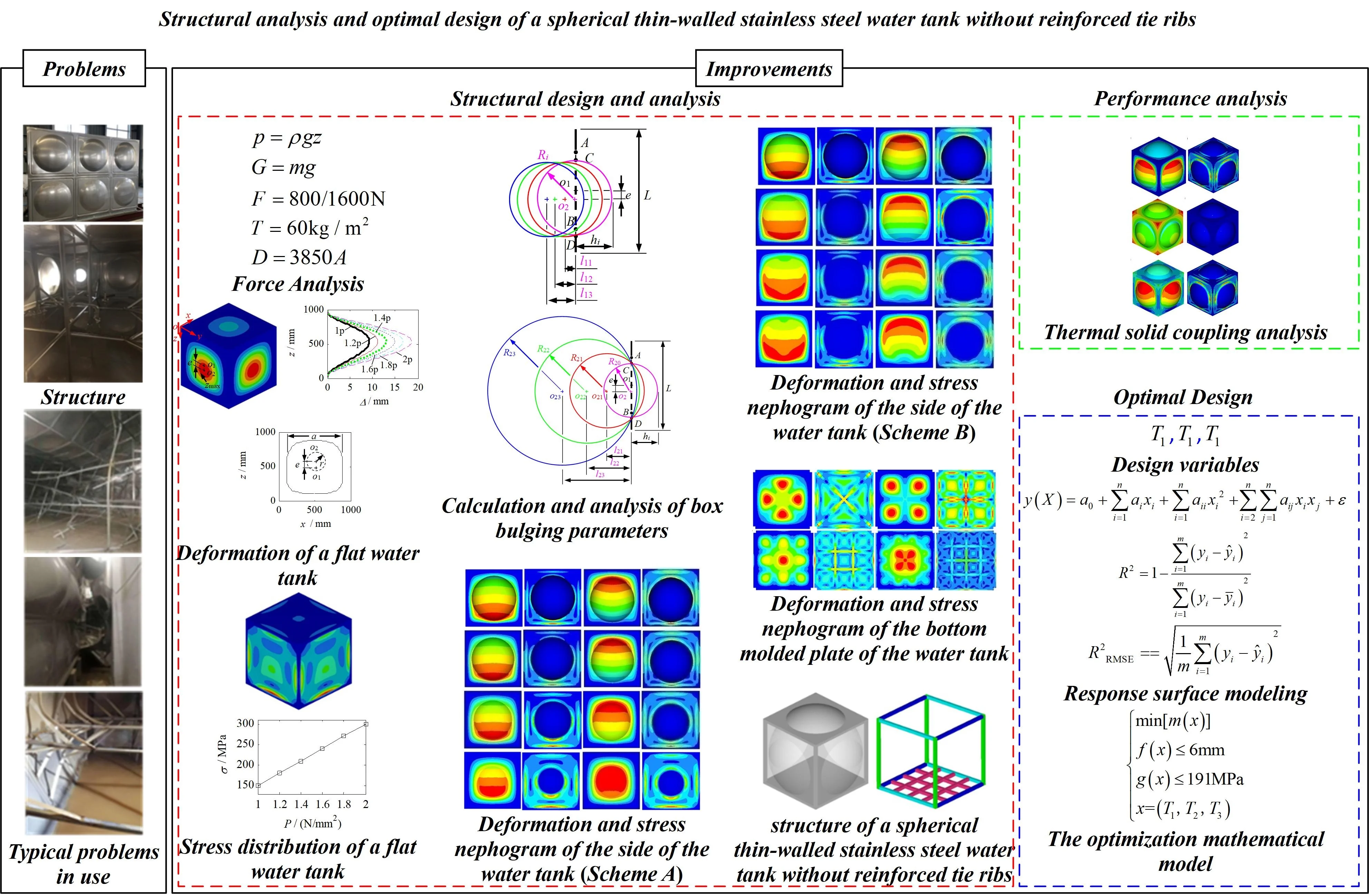
A spherical thin-walled stainless steel water tank without reinforced tie ribs has been designed to address the issues of easy fracture and corrosion of the ribs, difficulty in maintenance and cleaning, and short service life exposed during the use of thin-walled stainless steel water tanks with reinforced tie ribs. Firstly, an analytical model of a flat steel thin-walled water tank without reinforced tie ribs was established and subjected to static analysis under water pressure. The deformation and stress distribution patterns of the side molded plate of the flat box were obtained. Secondly, a spherical non ribbed thin-walled stainless steel water tank structure was designed with circular cross-section under different box bulge parameters, and its mechanical response characteristics under water pressure load were analyzed. A strengthening scheme was designed for the bottom box molded plate. Once again, optimize the combination design of the box scheme and the reinforcement scheme, and analyze their static, thermodynamic, and thermal solid coupling performance. Finally, the Latin Hypercube Sampling method was used to generate experimental design samples, and a response surface approximation model of a spherical thin-walled stainless steel water tank without reinforced tie ribs was constructed. The wall thickness of the box molded plate, skeleton, and reinforcement were used as design variables, and the maximum deformation and maximum equivalent stress were used as constraints. The lightweight design was carried out with the goal of minimizing mass. The research results indicate that the design program and parameter selection method for spherical thin-walled stainless steel water tanks without reinforced tie ribs proposed in the article are efficient and feasible, and can provide technical reference and theoretical support for the layout and overall optimization design of non ribbed thin-walled stainless steel water tank structures.
1. Introduction
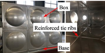
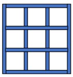
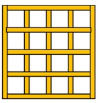
At present, international civil and industrial water tanks mainly include cement concrete pouring water tanks, whole steel plate welded water tanks, and prefabricated stainless steel water tanks. Cement concrete pouring water tanks and whole steel plate welded water tanks have disadvantages such as heavy weight, low strength, and difficult installation. However, prefabricated stainless steel water tanks have many advantages such as light weight, high strength, convenient assembly, and high cost-effectiveness, and are being increasingly applied [1-3]. Prefabricated stainless steel water tank, also known as ribbed stainless steel water tank, mainly consists of a box body, ribs, base, and accessories. Its structure is shown in Fig. 1. Among them, the box body is composed of multiple molded plates welded together. The molded plates often adopt a square structure with folded edges and a circular (or elliptical, cylindrical, or rectangular) bulge in the middle. The base adopts a frame structure composed of square tubes or I-shaped steel, and the tie ribs adopt a staggered structure composed of circular tubes or angle steel. The tie ribs are welded to the folding joint inside the molded plate of the box, which is used to support the box and prevent it from expanding and cracking. The box is welded to the base through the bottom molded plate.
Fig. 1Structure of water tank with reinforced tie ribs
With the widespread application of reinforced stainless steel water tanks, some problems have been exposed during use [4-5]. 1) The internal support braces of the water tank are prone to water corrosion, and the braces are likely to fracture after being put into use for a few years. After fracture, the box is easily deformed and may burst. 2) The difficulty of repairing and cleaning the water tank is high. After the first fracture of the local tie ribs, secondary welding is required. Due to the staggered arrangement of the tie ribs inside the box, the difficulty of maintenance will become greater. In addition, the accumulation of corrosive substances generated by water corrosion and the presence of tie ribs can also cause difficulties in cleaning. 3) The lifespan of the water tank is short, and frequent breakage and maintenance of the tie ribs, as well as the impact of water corrosion, can shorten the lifespan of the water tank. Fig. 2 shows typical problems in the use of water tanks with tie ribs.
Fig. 2Typical problems in the use of water tanks with reinforced tie ribs
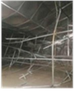
a) Reinforced tie ribs fracture
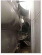
b) Box deformation
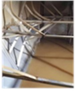
c) Reinforced tie ribs water corrosion
Nindhia T. G. T. et al. analyzed the corrosion failure of stainless steel water tanks, identified the causes of tank corrosion, and proposed solutions [6]. Aihemaiti·Yibulayin et al. conducted research on stainless steel water tanks buried underground and proposed effective measures to reduce the deflection of molded plates [7]. Sahoo N. used the working stress method to design circular and rectangular water tank structures considering flexible bases, and provided corresponding calculation programs [8]. Son B. J. et al. used finite element method to study the structural performance of large water tanks and obtained the relationship between different load combinations, water capacity, and stainless steel materials [9]. These studies are beneficial explorations aimed at solving the problems of stainless steel water tanks with braces. However, research on the structure of thin-walled stainless steel water tanks without reinforced tie ribs, which mainly withstand internal water pressure, has not yet been reported in relevant literature.
This article first establishes an analytical model for a flat thin-walled stainless steel water tank without reinforced tie ribs, and obtains the mechanical response characteristics of the tank under water pressure load; Then, based on the deformation center and stress distribution law of the flat box body, the size and position of the molded plate drum are used as variables to design various types of spherical non ribbed thin-walled stainless steel water tanks, and the static, thermodynamic, and thermal-structural coupling performance analysis is conducted on the selected water tanks; Finally, the response surface method was used to optimize the design of the spherical non ribbed thin-walled stainless steel water tank. The design program and parameter selection method for spherical non ribbed thin-walled stainless steel water tanks proposed in the article are efficient and feasible, providing technical reference and theoretical support for the layout and overall optimization design of non ribbed thin-walled stainless steel water tank structures.
2. Structural design and analysis of thin-walled stainless steel water tank without reinforced tie ribs
A thin-walled stainless steel water tank without reinforced tie ribs, that is, a water tank without tie ribs inside the tank, can avoid many problems caused by tie ribs. The design of a thin-walled stainless steel water tank without reinforced tie ribs must meet the requirements of stiffness and strength performance. Its structure cannot completely follow the structure of a thin-walled stainless steel water tank with tie ribs. It is necessary to consider alternative support schemes after the removal of tie ribs and the optimization design of the overall structure of the water tank. By calculating and selecting the parameters of each component of the water tank reasonably, high-quality water tanks can be designed.
2.1. Scheme design
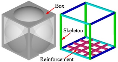
The thin-walled stainless steel water tank without tie bars is designed as a structure composed of components such as a box body, skeleton, reinforcement, and accessories. According to the stress situation and manufacturing process characteristics of the water tank, the box is designed as a welded structure consisting of side molded plates with different cross-sectional shapes, top molded plates, and bottom molded plates. The side and top molded plates are designed as flat plates with bulges to enhance their stiffness; The bottom molded plate is designed as a flat structure to facilitate the installation of the water tank and to add reinforcements to the bottom molded plate to reduce its deformation. The skeleton is designed as a frame structure composed of welded square tubes, and the reinforcement is designed as a staggered arrangement of square tubes. The inlet and outlet, ladder, and other accessories continue to use a thin-walled stainless steel water tank structure with tie bars. The box body is welded to the skeleton through molded plate folding, and the reinforcement is connected to the bottom frame of the skeleton through welding.
2.2. Force analysis
For rectangular water tanks installed outdoors, the actual external forces they are subjected to mainly include [3]:
1) The static water pressure generated after filling the water tank can be calculated by the following equation:
where, – density of water, – acceleration of gravity, and – water level.
When the water tank is filled with water, it is the maximum stress state of the water tank. According to Eq. (1), at this time, the water pressure on the top molded plate of the box is zero, and the water pressure on the side molded plate of the box gradually increases as the height of the water tank decreases until the bottom of the box reaches its maximum. The water pressure on the bottom molded plate of the box is uniform and constant, and the water pressure is the maximum.
2) The gravity generated by the self weight of the water tank is calculated as follows:
3) The concentrated load generated by carrying people on the top of the water tank is taken as follows in Table 1.
Table 1Concentrated load
Projected area of the top molded plate of the water tank / m2 | Concentrated load / N |
≤ 4 | 800 |
> 4 | 1600 |
4) The snow load generated by the snow accumulation on the top of the water tank is usually taken as 60 kg/m2.
5) Wind load , calculated as follows:
where, – the windward area of the water tank.
2.3. Calculation of deformation center and stress distribution of box body
According to the stress characteristics and structural symmetry of the water tank, it can be seen that the stress center of the non-ribbed thin-walled stainless steel water tank box, which mainly bears internal water pressure, coincides with the geometric center of the box in the long width direction, but does not coincide with the geometric center of the box in the height direction, and leans towards the lower part of the box. This will cause asymmetric forces on both sides of the box side molded plate at the geometric center of the box height, thereby affecting the deformation and stress distribution of the box side molded plate. So, before designing the side molded plate of the box, it is necessary to analyze the deformation and stress distribution of the box, find the force or deformation center of the side molded plate in the height direction, and then strengthen the bulge through reasonable design to ensure that the force or deformation of the side molded plate of the box is uniform.
Based on the aforementioned non ribbed thin-walled stainless steel water tank scheme, a flat plate non ribbed thin-walled stainless steel water tank with a volume of 1000 is designed, with a length, width, and height of 1000 mm. The skeleton and reinforcement are made of square tubes with a size of 40×40×2 mm, and the box molding plate is a flat plate structure with a thickness of 3 mm. The stress or deformation center of the flat thin-walled stainless steel water tank body is now determined through finite element method.
Establish a finite element model of the water tank in HyperMesh software, with a mesh size of 10 mm and a mesh quality that meets the calculation requirements [10-11]. The skeleton, reinforcement, and molded plate are all modeled using shell elements. The material grades of the skeleton and reinforcement are Q235A, and the material grades of the molded plate are SUS304. The stress-strain curve is shown in Fig. 3. From Fig. 3, it can be seen that the yield strength of Q235A and SUS304 are 235 MPa and 205 MPa, and the tensile strength is 375 MPa and 520 MPa. The weld connection is simulated using Rb2 elements. Loading conditions: Based on the force analysis in Section 2.2 and the size of the water tank, calculate the full load water pressure 1.0×10³ m3/kg×9.8 m/s2××10-3 m = 9.8× Pa. Apply water pressures of 1, 1.2, 1.4, 1.6, 1.8, and to the water tank model. The constraint condition: in order to reduce the impact of rigid constraints on the simulation results, the constraint is released through inertia, that is, by applying false constraint reactions on the structure to ensure the force balance of the structure [12-16]. Submit the built model to OptiStruct software for calculation, with solver parameters set to: export options select custom, run options select analysis, and memory options select memory default. After the calculation is completed, view the calculation results in HyperView software, as shown in Fig. 4 and Fig. 5.
Fig. 4 shows the deformation of the side molded plate of a flat thin-walled stainless steel water tank. From Fig. 4(a) and 4(b), it can be seen that the deformation of the side molded plate of the water tank increases with the increase of the full load water pressure multiple. The deformation curve in the height direction is approximately V-shaped, and reaches its maximum value at the lower position of the height center. Use Matlab software to fit the areas with significant deformation, and the fitting results are shown in Fig. 4(c). From Fig. 4(c), it can be seen that the deformation area of the molded plate on the side of the water tank is concentrated in an approximate square area with a side length of mm centered on the geometric center of the side shifted downwards by mm, and the maximum deformation occurs in the circle with the center of the deformation area as the center and mm as the radius.
Fig. 3Material stress-strain curve
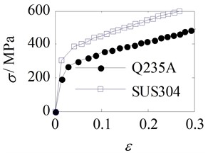
Fig. 4Deformation of the side molded plate of a flat thin-walled stainless steel water tank without reinforced tie ribs under hydrostatic pressure
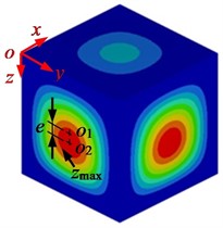
a) Deformation nephogram
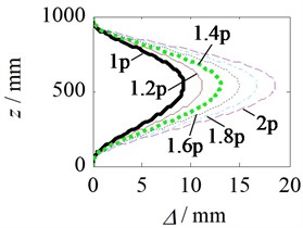
b) Deformation curve
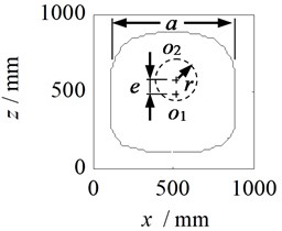
c) Deformation area fitting curve
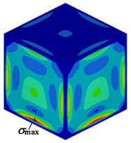
Fig. 5 shows the stress distribution of the molded plate on the side of a flat thin-walled stainless steel water tank. It can be seen from Fig. 5 that the stress in the water tank is approximately proportional to the full load water pressure multiple, and the stress is highest at the side of the water tank near the bottom crossbeam of the skeleton.
Fig. 5Stress distribution of the side molded plate of a flat thin-walled stainless steel water tank without reinforced tie ribs under hydrostatic pressure
a) Stress nephogram
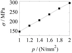
b) Maximum equivalent stress
2.4. Calculation and analysis of box bulging parameters
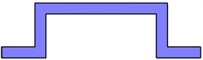
According to the above analysis, the deformation of the side molded plate of the flat thin-walled stainless steel water tank without tie bars is concentrated in a specific area, indicating that the stiffness in this area is weak and needs to be strengthened. The deformation of a flat plate is closely related to its cross-sectional shape, so bulges with different cross-sectional shapes can be designed in this area to reduce deformation. Common cross-sectional shapes include circular, elliptical, cylindrical, and rectangular sections, as shown in Fig. 6.
Fig. 6Common cross-sectional shapes of bulges

a) Circular cross-section

b) Elliptical cross-section

c) Cylindrical cross-section
d) Rectangular cross-section
Taking a circular cross-section as an example, design the size parameters of the box bulge. Two types of box side bulging structures were designed in the article. Scheme A, as shown in Fig. 7, takes a point on the horizontal line of the geometric center on the side of the water tank (a point on the horizontal line of the center of the deformation area on the side of the water tank) as the center of the circle, and takes the maximum outer contour of the deformation area on the side as the diameter. Draw a spherical drum that intersects with the side at points A (C) and B (D), and the arc AB (CD) is the outline of the drum. Scheme B, as shown in Fig. 8, takes the point on the horizontal line of the geometric center on the side of the water tank (the point on the horizontal line of the center of the deformation area on the side of the water tank) as the center of the circle, and takes the maximum outer contour of the deformation area on the side as the envelope. Draw a spherical bulge that intersects with the side at points A (C) and B (D), and the arc AB (CD) is the bulge contour. Among them, is the height dimension of the water tank, and is the envelope radius of the deformation area on the side of the water tank. In these two schemes, the drum drawn with a point on the horizontal line of the geometric center on the side of the water tank as the center is called an eccentric drum; A bulge drawn with a point on the horizontal line of the center of the deformation area on the side of the water tank as the center is called an eccentric bulge.
Fig. 7Bulge (Scheme A)
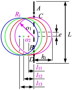
Fig. 8Bulge (Scheme B)
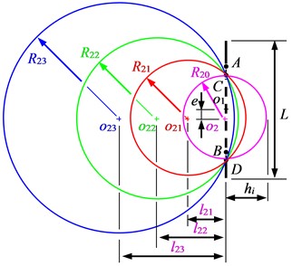
To select the appropriate size and position of the bulge, the horizontal distance between the center of the bulge and the geometric center of the side of the water tank or the center of the deformation area on the side of the water tank is taken as . When takes different values, the values of the bulge radius and height are shown in Table 2. Using HyperMesh software, establish finite element models of the spherical water tank with different bulge size parameters. The modeling process is the same as that of the flat plate non ribbed water tank mentioned above. Apply 1 water pressure to the constructed water tank model, set the constraint conditions and solver parameters as in Section 2.3. Submit the water tank model to the solver for calculation, and obtain deformation and stress cloud maps of the side of the spherical non ribbed thin-walled stainless steel water tank, as shown in Table 3 and Table 4.
Table 2Bulge parameters
Scheme A | Group | / mm | / mm | / mm | Scheme B | Group | / mm | / mm | / mm |
0 | 390 | 390 | 0 | 390 | 390 | ||||
100 | 390 | 290 | 300 | 492 | 192 | ||||
200 | 390 | 190 | 600 | 716 | 116 | ||||
300 | 390 | 90 | 900 | 981 | 81 |
From Table 3, it can be seen that Scheme A, in which the deformation and stress on the side of the water tank increase with the decrease of the height of the drum, while the diameter of the drum remains unchanged and only the position of the drum center is changed. The deformation and stress on the side of the water tank are sensitive to the height of the bulge. The larger the height of the bulge, the smaller the deformation and stress on the side of the water tank. The difference in maximum deformation between non eccentric and eccentric bulges is not significant, but there is a significant difference in the distribution of deformation areas. The maximum deformation area of non eccentric bulges is located in the lower area of contact between the bulge and the side of the water tank, while the maximum deformation area of eccentric bulges is located in the upper area of contact between the bulge and the side of the water tank.
Table 3Deformation and stress nephogram of the side of the water tank (Scheme A)
Scheme | Non eccentricity | Eccentric | ||||||
Displacement nephogram | / mm | Stress nephogram | / MPa | Displacement nephogram | / mm | Stress nephogram | / MPa | |
 | 0.39 |  | 76.25 |  | 0.45 |  | 40.66 | |
 | 0.54 |  | 82.09 |  | 0.57 |  | 56.14 | |
 | 1.2 |  | 97.45 |  | 1.09 |  | 85.86 | |
 | 3.23 |  | 118.40 |  | 2.77 |  | 114 | |
The maximum stress of the non-eccentric drum is significantly higher than that of the eccentric drum, and the maximum stress of the non-eccentric drum is concentrated in the lower area where the drum contacts the side of the box. The maximum stress of the eccentric drum is evenly distributed in the area where the drum contacts the side of the water tank, and the stress distribution is more reasonable than that of the non-eccentric drum. The maximum deformation of the side of the water tank is less sensitive to the location of the bulge, while the maximum stress of the side of the water tank is more sensitive to the location of the bulge.
From Table 4, it can be seen that in Scheme B, where the envelope area of the bulge on the side of the water tank remains unchanged and only the center position of the bulge is changed, the deformation and stress changes on the side of the water tank vary little with the height of the bulge. Explain the insensitivity of deformation and stress on the side of the water tank to changes in bulging height. The deformation and stress distribution of non-eccentric bulges and eccentric bulges are basically the same as Scheme A, but the maximum deformation and maximum stress are significantly smaller than Scheme A, and the maximum stress value of non-eccentric bulges is significantly higher than that of eccentric bulges. This indicates that Scheme B is more reasonable than Scheme A, and the eccentric bulging scheme in Scheme B is significantly better than the non-eccentric bulging scheme.
Table 4Deformation and stress nephogram of the side of the water tank (Scheme B)
Scheme | Non eccentricity | Eccentric | ||||||
Displacement nephogram | / mm | Stress nephogram | Displacement nephogram | / mm | / mm | Displacement nephogram | / mm | |
 | 0.39 |  | 76.25 |  | 0.45 |  | 40.66 | |
 | 0.40 |  | 74.63 |  | 0.47 |  | 40.45 | |
 | 0.41 |  | 74.04 |  | 0.46 |  | 41.46 | |
 | 0.44 |  | 74.42 |  | 0.48 |  | 42.97 | |
2.5. Design and analysis of box reinforcement
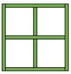
Considering that the top and side molded plates of the box are subjected to relatively small forces, both use a flat plate structure with a drum, without the need for additional reinforcement. However, considering that the bottom molded plate of the box has the maximum force and is designed as a flat plate structure, it is necessary to add reinforcement to the bottom molded plate of the box. Common reinforcements include X-shaped, cross shaped, well shaped, and mesh shaped square tube reinforcement structures, as shown in Fig. 9.
Fig. 9Scheme for strengthening the square tube of the molded plate at the bottom of the box body
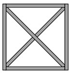
a) X-shaped
b) Cross shaped
c) Well shaped
d) Mesh shaped
Using HyperMesh software, establish a finite element model of a spherical non ribbed thin-walled stainless steel water tank containing different stiffeners for the bottom molded plate of the tank. The modeling process, loading conditions, constraint conditions, and solver parameter settings are the same as the modeling process of the spherical non ribbed thin-walled stainless steel water tank mentioned above. A 1 water pressure is applied to the constructed water tank model to obtain the deformation and stress cloud map of the bottom mold pressing plate of the spherical non ribbed thin-walled stainless steel water tank, as shown in Table 5. From Table 5, it can be seen that using X-shaped, cross shaped, well shaped, and mesh shaped reinforcements, the maximum deformation of the bottom molded plate of the box is 0.80 mm, 1.06 mm, 0.36 mm, and 0.19 mm, respectively, and the maximum stress is 41.15 MPa, 37.07 MPa, 28.42 MPa, and 29.63 MPa, respectively. The maximum displacement and maximum stress values show a decreasing trend in sequence. This indicates that the mesh shaped reinforcement has the best effect, followed by the well shaped reinforcement, and the cross shaped and X-shaped reinforcement have the worst effect.
Table 5Deformation and stress nephogram of the bottom molded plate of the water tank
Displacement nephogram | / mm | Stress nephogram | / MPa | Displacement nephogram | / mm | Stress nephogram | / MPa |
 | 0.80 |  | 41.15 |  | 1.06 |  | 37.07 |
X-shaped | Cross shaped | ||||||
 | 0.36 |  | 28.42 |  | 0.19 |  | 29.63 |
Well shaped | Mesh shaped | ||||||
Based on the above analysis, the combination of the box scheme and the reinforcement scheme is selected to design a spherical non ribbed thin-walled stainless steel water tank. Among them, the B1 scheme in Scheme B is adopted for the top and side molded plate drum of the box, the non eccentric scheme is adopted for the top molded plate drum of the box, the eccentric scheme is adopted for the side molded plate drum of the box, and the flat plate structure is adopted for the bottom molded plate of the box. The reinforcement adopts a mesh shaped square tube reinforcement structure to strengthen the bottom molded plate, and the skeleton adopts a combined square tube frame structure. Using Catia software to digitize geometric modeling, a spherical non ribbed thin-walled stainless steel water tank structure was obtained, as shown in Fig. 10.
Fig. 10Schematic diagram of the structure of a spherical thin-walled stainless steel water tank without reinforced tie ribs
3. Performance analysis
3.1. Static analysis
Import the digital geometric model of the selected spherical non ribbed thin-walled stainless steel water tank into HyperMesh software, and perform necessary simplification treatments while ensuring its performance, such as ignoring the influence of accessories such as inlet and outlet, ladders, and deleting features such as rounded corners and chamfers. Considering computational efficiency and accuracy, a preliminary analysis was conducted using 20 mm, 10 mm, and 5 mm shell element grids when dividing the grid. After comprehensive comparison of the calculation results, a 10 mm shell element grid was ultimately selected with a mesh number of 99552 and 86079 nodes. The weld connections between the box and the skeleton, as well as between the skeleton and the reinforcement, are simulated using Rb2 elements.
The material of the skeleton and reinforcement is Q235A, and the material of the box is SUS304. According to the ‘Mechanical Design Manual’ [17] and the plate thickness, the allowable stress calculation formula for the two materials is:
where – yield strength; – tensile strength; – safety factor.
Substituting the yield strength of Q235A with = 235 MPa and tensile strength = 375 MPa, and the yield strength of SUS304 with = 205 MPa and tensile strength = 520 MPa into Eq. (4), with a safety factor of 1.3, the allowable stresses of Q235A and SUS304 are 191 MPa and 219 MPa, respectively
The strength analysis uses the fourth strength theory to determine whether the structure has failed. The Von Mises stress of the spherical unreinforced water tank is [18]:
where , , – the first principal stress, the second principal stress, and the third principal stress.
The stiffness is determined by deformation theory to determine whether it meets the requirements. The total deflection of a spherical unreinforced water tank is:
where , , – deformation on the , , and axes; – allowable deflection, for thin-walled sheet metal parts, the allowable deflection is generally taken as ≤ 6 mm [19].
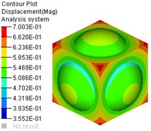
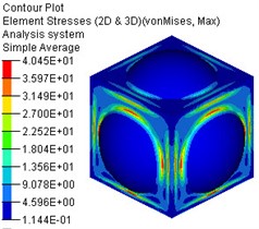
Apply full load water pressure to the water tank model, with the same constraints and solver parameter settings as in Section 2.3. Submit the built model to OptiStruct software for calculation, and view the calculation results in HyperView software, as shown in Fig. 11.
From Fig. 11, it can be seen that under the full load water pressure condition, the maximum total deflection of the spherical unreinforced water tank is 0.46 mm, and the maximum Von Mises stress is 40.45 MPa. The maximum total deflection and maximum Von Mises stress are both less than the allowable deflection and allowable stress.
3.2. Thermodynamic analysis
For outdoor water tanks, deformation and stress fields can occur in high temperature environments in summer or when hot water is filled. Due to the slow occurrence of temperature changes, thermodynamic analysis only needs to focus on the deformation and thermal stress of the water tank when the temperature uniformly reaches 80 ℃ from room temperature of 20 ℃.
Fig. 11Deformation and stress nephogram of water tank under static force
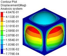
a) Deformation nephogram
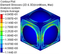
b) Stress nephogram
Using the water tank model established in static analysis, set the heat transfer coefficient of the material in the material card 1.0×10⁻⁵/℃, define the initial temperature load 20 ℃ and the temperature load 80 ℃ after heating, and apply the temperature as a load similar to displacement on the grid nodes of the water tank to establish a thermodynamic analysis model of the water tank [20]. The constraint conditions and solver parameter settings are the same as in section 2.3. Submit the thermodynamic model to the solver for calculation, and the calculation results are shown in Fig. 12. From Fig. 12, it can be seen that when the temperature rises from 20 ℃ to 80 ℃, the maximum total deflection of the water tank is 0.70 mm, and the maximum Von Mises thermal stress is almost zero. This is because the constraint condition used in the simulation is inertia release, and the water tank can deform freely after being heated. The maximum total deflection and maximum Von Mises stress are both less than the allowable deflection and allowable stress.
Fig. 12Nephogram of water tank deformation and stress under thermal action (20-80 ℃)
a) Deformation nephogram
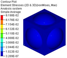
b) Stress nephogram
3.3. Thermal solid coupling analysis
The water tank bears the dual effects of water pressure and heat during operation, which is a typical type of thermal solid coupling analysis. Considering the actual situation, the deformation and stress of the solid structure of the water tank depend on the temperature field, which is weakly affected by the deformation and stress of the solid structure. When analyzing, the temperature field is first analyzed, and then the calculated temperature is applied to the structure in the form of a temperature load to obtain the deformation and stress distribution of the structure.
Based on the aforementioned static analysis model of the water tank, the joint loading of the load for the thermal solid coupling analysis of the water tank was achieved through the TEMP and LOAD control cards in the Subcase Definition control card of OptiStruct software [21]. The setting of the TEMP control card is the same as that of the thermodynamic analysis in Section 3.2, and the setting of the LOAD control card is the same as that of the static analysis in Section 3.1. The thermal structural coupling model of the water tank is submitted for calculation, the results of the thermal solid coupling analysis of the water tank are shown in Fig. 13 From Fig. 13, it can be seen that the maximum total deflection of the water tank is 0.93 mm, which is higher than the maximum total deflection under the separate action of water pressure and heat. The maximum Von Mises is 40.45 MPa, which is basically the same as the stress under the separate action of water pressure. If the boundary constraint condition of inertia release is used, the influence of thermal stress on the water tank can be ignored.
Fig. 13Deformation and stress nephogram of water tank under thermal solid coupling effect
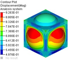
a) Deformation nephogram
b) Stress nephogram
3.4. Result analysis
Based on the above analysis, the spherical non ribbed thin-walled stainless steel water tank designed in the article meets the requirements for stiffness and strength under static, thermodynamic, and thermal solid coupling conditions, and has a large optimization design space, which can be used for lightweight design of the water tank.
4. Optimal design
4.1. Design variables
The most effective method for lightweight design is to reduce the wall thickness of each component. In this paper, the wall thickness of the box molded plate, skeleton, and reinforcement is used as a variable for optimization design. The values of each design variable are shown in Table 6.
Table 6Optimization design variable values
Design variables | Value before optimization | Value range |
Thickness of box molded plate / mm | 3 | 0.5-3 |
Thickness of skeleton square tube / mm | 2 | 0.5-2 |
Reinforcement square tube thickness / mm | 2 | 0.5-2 |
4.2. Design of experiment
Design of experiment is achieved by scientifically and reasonably arranging experimental plans and data to achieve ideal experimental results. Latin Hypercube Sampling can effectively construct approximate models with fewer samples. Its basic principle is to divide the value range of random design variables into equal probability non repeating subintervals based on the number of required sample points . In each subinterval, a point is randomly selected according to its probability distribution, and selected points of random design variables are randomly combined [21]. Using the Latin hypercube experimental sampling method, 20 sample points were generated in the sample space, and the response values corresponding to the sample points were obtained through finite element numerical calculation, as shown in Table 7.
Table 7Latin hypercube sampling test points
Sample number | / mm | / mm | / mm | Maximum deformation / mm | Maximum equivalent stress / MPa | Mass of water tank / kg |
1 | 2.87 | 0.57 | 1.77 | 1.30 | 66.63 | 171.34 |
2 | 1.41 | 1.08 | 1.81 | 4.31 | 238.89 | 100.64 |
3 | 2.33 | 1.42 | 1.65 | 1.50 | 94.94 | 150.33 |
4 | 2.10 | 1.18 | 1.49 | 1.86 | 113.33 | 136.39 |
5 | 2.72 | 1.59 | 1.22 | 1.13 | 71.06 | 171.27 |
6 | 0.79 | 1.89 | 0.62 | 16.83 | 740.73 | 72.87 |
7 | 2.89 | 1.95 | 0.99 | 0.98 | 62.27 | 184.61 |
8 | 2.38 | 1.02 | 0.57 | 1.60 | 95.73 | 143.02 |
9 | 1.59 | 1.26 | 1.87 | 3.03 | 185.52 | 114.57 |
10 | 2.52 | 0.61 | 0.77 | 1.70 | 89.50 | 143.82 |
11 | 0.93 | 0.70 | 0.66 | 14.39 | 554.73 | 61.51 |
12 | 2.20 | 1.78 | 0.87 | 1.48 | 103.39 | 146.15 |
13 | 1.01 | 0.86 | 1.42 | 10.21 | 454.00 | 74.30 |
14 | 1.70 | 1.12 | 1.37 | 2.87 | 167.28 | 113.51 |
15 | 0.59 | 0.73 | 1.08 | 40.92 | 1224.68 | 48.63 |
16 | 1.80 | 1.36 | 0.88 | 2.32 | 150.40 | 119.64 |
17 | 1.18 | 1.72 | 1.11 | 5.60 | 332.74 | 94.14 |
18 | 1.94 | 0.94 | 1.98 | 2.54 | 144.20 | 125.08 |
19 | 1.25 | 1.63 | 1.27 | 4.62 | 282.26 | 99.25 |
20 | 0.72 | 1.50 | 1.55 | 24.82 | 945.21 | 68.68 |
4.3. Response surface modeling
Response surface method is a method of constructing approximate models by conducting limited experimental designs on a set of sample points in a specified design space, fitting the design space with appropriate iterative strategies, and replacing the real response surface with a global approximation of the output variables. The implicit function is expressed as a polynomial with a clear expression. At present, the main methods for constructing response surfaces include polynomial, exponential and logarithmic function fitting, neural network approximation, and so on. The polynomial approximation model can handle various nonlinear problems. Therefore, in practical applications, regardless of the relationship between the design variables and the objective function, polynomial approximation models can be used for analysis [22].
For a model with design variables, the quadratic polynomial response surface model can be represented as:
where , – design variable, , , , – undetermined coefficient of quadratic polynomial, – statistical error.
The determination coefficient is commonly used to test the accuracy of fitting surfaces, and the closer its value is to 1, the higher the accuracy of the response surface model. Considering the stability of the model, the root mean square error is introduced to jointly evaluate the effectiveness of the response surface model. Its expression is:
where – the response value corresponding to the -th sample point, – the predicted response value obtained by the response surface model.
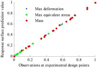
Perform error analysis on the response surface model using Eqs. (8) and (9), and the results are shown in Table 8. From Table 8, it can be seen that the determination coefficients of each response are close to the ideal value of 1, and the root mean square error of the determination coefficients is relatively small, close to the ideal value of 0. Normalizing the response face value, as shown in Fig. 14, it can be seen that the predicted response surface values of each objective function and the observed values of the test points are basically the same, all clustered on both sides of the identification line. Based on the above analysis, it can be seen that the response surface model in the article has high fitting accuracy and can effectively predict the true response values of design variables.
Table 8Error analysis
Objective function | Coefficient of determination | RMS error of determining coefficients |
Maximum deformation | 0.9999617 | 0.0022187 |
Maximum equivalent stress | 0.9999901 | 0.0012449 |
Mass of water tank | 0.9982129 | 0.0016168 |
Ideal value | 1 | 0 |
Fig. 14Normalized values of response surface
4.4. Structural optimization
Set the minimum mass of the water tank as the objective function, and set the maximum deformation not exceeding 6mm and the maximum equivalent stress not exceeding the allowable stress as constraint conditions. The optimization mathematical model for the structure of a spherical non ribbed thin-walled stainless steel water tank is as follows:
where , , – mass, maximum deformation, and maximum equivalent stress, – design variables.
Using HyperStudy software, call the calculation result file of the aforementioned water tank thermal solid coupling analysis model, and use the wall thickness of the box molded plate, skeleton, and reinforcement in the file as variables for the optimization design of thermal solid coupling. Select the OptiStruct solver for calculation, and set the solver parameters to: export options select custom, run options select optimization, and memory options select upper limit in 2000. After 23 iterations, reach the convergence condition. The iterative process of each response is shown in Fig. 15.
Fig. 15Iteration process of each response value
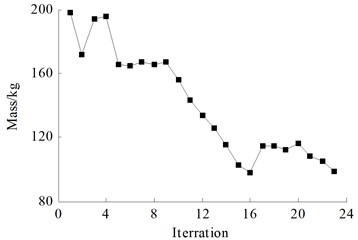

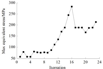
After optimization, the optimal solution of the design variables was obtained. After rounding it, a thermal solid coupling analysis was conducted on the spherical non ribbed thin-walled stainless steel water tank at this design point. The results are shown in Table 9. By comparison, it was found that the predicted values of the response surface were very close to the calculated values. It was explained that the fitting accuracy of the response surface in the text was high, and the optimized water tank mass decreased by 93.04 kg, with a decrease of 47 %. The maximum deformation was only 3.24 mm, and the maximum equivalent stress was 188.03 MPa, both within the allowable range of the material.
Table 9Comparison of results before and after optimization
Parameter | / mm | / mm | / mm | Maximum deformation / mm | Maximum equivalent stress / MPa | Mass / kg |
Calculated value before optimization | 3.0 | 2.0 | 2.0 | 0.93 | 40.45 | 197.99 |
Calculated value after optimization | 1.62 | 1.11 | 0.92 | 3.24 | 188.03 | 104.95 |
Calculated value after rounding | 1.6 | 1.1 | 1 | 3.24 | 187.84 | 105.62 |
5. Conclusions
1) Under the action of static water pressure, the deformation area of the molded plate on the side of the water tank is concentrated in an approximate square area with a side length of mm centered on the geometric center of the side shifted downwards by mm, and the maximum deformation occurs in the circle with the center of the deformation area as the center and mm as the radius. The stress is approximately proportional to the multiple of full load water pressure, and the maximum stress is located on the side of the water tank near the bottom crossbeam of the skeleton.
2) When the diameter of the bulge in a spherical non ribbed thin-walled stainless steel water tank remains unchanged and only the center position of the bulge is changed, the deformation and stress on the side of the water tank are sensitive to the bulge position, and the effect of eccentric bulge is better than that of non-eccentric bulge. When the envelope area of the drum on the side of the water tank remains unchanged and only the center position of the drum is changed, the deformation and stress on the side of the water tank are not sensitive to the position of the drum, but have smaller deformation and stress.
3) From the effect of the molded plate reinforcement at the bottom of the box, the mesh reinforcement has the best effect, followed by the well shaped reinforcement, and the cross shaped and X-shaped reinforcement have the worst effect.
4) The Latin hypercube experimental design method was used to effectively construct a response surface approximation model of a spherical non ribbed thin-walled stainless steel water tank with fewer samples, establishing the implicit relationship between structural parameters and structural performance, providing ideas for similar research projects. The thermal solid coupling analysis method used in the article has a certain guiding role for multidisciplinary coupling analysis.
References
-
Y. Wang, J. Y. R. Liew, and S. C. Lee, “Structural performance of water tank under static and dynamic pressure loading,” International Journal of Impact Engineering, Vol. 85, pp. 110–123, Nov. 2015, https://doi.org/10.1016/j.ijimpeng.2015.06.018
-
M. Dilena, M. F. Dell’Oste, A. Gubana, A. Morassi, F. Polentarutti, and E. Puntel, “Structural survey of old reinforced concrete elevated water tanks in an earthquake-prone area,” Engineering Structures, Vol. 234, p. 111947, May 2021, https://doi.org/10.1016/j.engstruct.2021.111947
-
Y. Wang, “Analysis and calculation of the structure of a fast-installing rectangle stainless steel water tank,” (in Chinese), Chemical Engineering and Machinery, Vol. 30, No. 2, 2003.
-
X. Ma et al., “Experimental study on the strength of complex thin-walled structures under internal pressure,” (in Chinese), Journal of Mechanical Strength, Vol. 29, No. 2, pp. 217–222, 2007.
-
X. Ma et al., “Numerical simulation and experimental validation on complex thin-walled structures under internal pressure load,” (in Chinese), Chinese Journal of Mechanical Engineering, Vol. 42, No. 7, pp. 211–216, 2006.
-
T. G. Tirta Nindhia, I. P. Widya Semara, I. W. Bandem Adnyana, I. W. Surata, and I. G. Komang Dwijana, “Failure analyses on corrosion of hot water tank storage made from stainless steel,” in IOP Conference Series: Materials Science and Engineering, Vol. 1007, No. 1, p. 012108, Dec. 2020, https://doi.org/10.1088/1757-899x/1007/1/012108
-
Y. Aihemaiti·, G. Zhang, and J. Han, “Compressive test and finite element optimization on molded plate of stainless steel water tank,” (in Chinese), Journal of Jiangsu University (Natual Science Edition), Vol. 37, No. 2, pp. 162–167, 2016, https://doi.org/10.3969/j.issn.1671-7775.2016.02.007
-
Sahoo N., “Design of water tank,” National Institute of Technology, Rourkela, 2008.
-
S. Byung-Jik and L. Sang-Youl, “Finite element stress analysis of large sized rectangular water tank structures made of stainless steel materials,” Journal of the Korean Society for Advanced Composite Structures, Vol. 6, No. 2, pp. 85–90, Jun. 2015, https://doi.org/10.11004/kosacs.2015.6.2.085
-
Wang Kefei et al., “Static stiffness analysis of automotive BIW under different boundary constraint conditions,” (in Chinese), Chinese Journal of Engineering design, Vol. 26, No. 4, pp. 441–451, 2019, https://doi.org/10.3785/j.issn.1006-754x.2019.04.010
-
K. Wang, P. Shi, and Z. Zhang, “Finite element modeling of electric vehicle power battery pack and its influence analysis and test research at body-in-white stage,” Journal of Vibroengineering, Vol. 25, No. 7, pp. 1353–1368, Nov. 2023, https://doi.org/10.21595/jve.2023.23260
-
H. Pengqiu and Q. Sun, “Modified inertia relief method based on accurate inertia loads,” AIAA Journal, Vol. 55, No. 8, pp. 2848–2852, Aug. 2017, https://doi.org/10.2514/1.j055557
-
T. Saito, H. Jiro, and U. Toshiaki, “A study of optimization for automotive parts and structures by using inertia relief,” in Proceedings of the 11th World Congress on Structural and Multidisciplinary Optimization, Vol. 7, 2015.
-
Sun Hui et al., “Structural analysis of new energy vehicle frame based on inertia relief,” (in Chinese), Automobile Technology, No. 12, pp. 55–58, 2018, https://doi.org/10.19620/j.cnki.1000-3703.20170069
-
Wang Yang et al., “Application of inertia relief in the prediction of welding deformation for large complex structures,” (in Chinese), Journal of Ship Mechanics, Vol. 20, No. 9, pp. 1147–1159, 2016.
-
K. Yan and G. Chen, “Application of the inertia relief method and improved inertia relief method in crashworthiness topology optimization problem,” (in Chinese), Chinese Journal of Computational Mechanics, Vol. 32, No. 3, pp. 293–300, 2015.
-
Wen Bangchun, Mechanical Design Manual. 6th edition. (in Chinese), Beijing: Mechanical Industry Press, 2018.
-
L. Zhang et al., “Crane jib structure design and section dimension optimization for lightweight targe,” Journal of Machine Design, Vol. 40, No. 6, pp. 124–133, 2023, https://doi.org/10.13841/j.cnki.jxsj.2023.06.026
-
S. Bao, C. Jiang, and J. Ding, “Optimum design of water tank for EMU based on response surface model and multi-objective genetic algorithms,” (in Chinese), Science Technology and Engineering, Vol. 19, No. 27, pp. 344–350, 2019.
-
C. Xu, M. Liu, H. Tang, J. Wang, and J. Yan, “Thermodynamic analysis of the thermocline storage tank with time-varying charging parameters,” Applied Thermal Engineering, Vol. 219, p. 119477, Jan. 2023, https://doi.org/10.1016/j.applthermaleng.2022.119477
-
B. T. Oh, “Analysis and optimization using numerical and experimental evaluation methods for multidisciplinary design problems,” Texas A&M University, 2009.
-
Q. Hao, L. Yang, and L. Cao, “Optimization of the stiffness of a car body based on response surface method,” (in Chinese), Mechanical Science and Technology for Aerospace Engineering, Vol. 29, No. 11, pp. 1569–1577, 2010, https://doi.org/10.13433/j.cnki.1003-8728.2010.11.025
About this article

The authors would like to thank the financial supports of the general project of Natural Science Research in Anhui University and the Youth Scientific Research Fund Project of Anhui Institute of Information Technology (22QNJKJ004), Wuhu City Applied Basic Research Project (2023jc21), and Intelligent Detection Research Team Funds of the Anhui Institute of Information Technology (23kytdpy001).
The datasets generated during and/or analyzed during the current study are available from the corresponding author on reasonable request.
Kefei Wang: Lead the research, ideas, simulation analysis and writing. Long Li: technical support and coordination of research activities.
The authors declare that they have no conflict of interest.
