Abstract
One important characteristic of base-isolated liquid storage structure (LSS) is that the vibration periods of structure and liquid are different, namely, there are two kinds of periods in the system. As a result, structure or liquid resonance may occurs under external excitation. In order to reflect the nonlinear characteristics of liquid sloshing, subsonic potential-based element is used to simulate the liquid. The governing equations of liquid field and fluid-structure interaction (FSI) equations are established; the initial and boundary conditions of liquid sloshing in dynamic coordinate system are obtained. Harmonic functions used to conduct time history analysis are generated by the first order vibration frequencies of structure and liquid respectively. The dynamic responses of base-isolated rectangular liquid storage structure (RLSS) under two types of resonance are studied comparatively. Results show that when the external excitation frequency is equal to the first order vibration frequency of isolated structure or liquid sloshing, wall tensile stress, structure displacement, base shear force and liquid sloshing wave height will appear resonance amplification phenomenon. The dynamic responses of structure itself caused by structure resonance are greater than that of liquid resonance; while the liquid sloshing wave height caused by liquid resonance is greater than that of structure resonance. Under structure resonance, the wall is prone to be cracked; and under liquid resonance, the liquid velocity field will become unusually violent, and liquid overflow will be caused easily.
Highlights
- Liquid governing and fluid-structure interaction equations are established based on subsonic potential flow theory.
- Dynamic responses of base-isolated rectangular liquid storage structure under structure and liquid resonances are studied comparatively.
- Influences of structure and liquid resonances on system dynamic responses are very different.
1. Introduction
Concrete RLSSs are widely used in water supply and drainage, sewage treatment, oil and chemical industry, railway and roof TLD. Once the seismic capacity of this type of structure is insufficient, under the action of earthquake, not only the structure itself will be destroyed, but also liquid leakage will be caused, as a result, environmental pollution, fire and the other secondary disasters will happen, even the people's life will be threatened seriously. Research of safety and shock absorption measure of this kind of engineering under earthquake and other external actions is of great significance for material reserves, disaster prevention, rescue and disaster relief and post-disaster reconstruction.
As a good damping method, rubber isolation has a wide application in civil engineering, and scholars have also done a lot of research on its application in LSS. Kim and Lee [1] used the substructure technique to simulate the influence of hydrodynamic force on structure, and evaluated the seismic performance of base-isolated LSS by pseudo-dynamic test. Chalhoub and Kelly [2] found that the total hydrodynamic pressure was effectively reduced, but the liquid sloshing height was increased slightly after the rubber isolation being taken. Malhotra [3, 4] proposed a new calculation method of seismic responses of rubber isolation LSS, found that rubber isolation could effectively reduce overturning moment and wall compressive stress, but its reduction effect on liquid sloshing height was not obvious. Jadhav and Jangid [5] studied the seismic responses of isolation LSS by three-particle model, and analyzed the main parameters affecting the isolation effect. Shrimali and Jangid [6] simplified the LSS as mass-spring model, studied the seismic responses of LSS with different sizes and different damping layers by modal superposition method and response spectrum method, and proved that the solution obtained by the simplified method and the accurate method are well matched. Soil-structure interaction is an important feature of the system, which has a significant effect on the dynamic response of the system [7-11], Cho et al. [12] evaluated accurately the seismic response of a liquid storage tank considering soil-structure interaction effect. Shekari and Khaji [13] simulated the isolation bearing with bilinear hysteretic element, and studied the seismic responses of base-isolated LSSs by finite element method. Sun et al. [14] established the simplified mechanical model of LSS considering liquid sloshing, FSI and wall elasticity, and obtained the theoretical equations of tank hydrodynamic pressure, wave height, base shear force and bending moment. Saha et al. [15] studied the dynamic responses of base-isolated LSSs under bi-directional seismic action based on two-particle and three-particle model, and found that the sloshing displacements corresponding to the two-particle and the three-particle model were basically equal, but the two-particle model underestimated the base shear, overturning moment and isolation layer displacement. Vosoughifar and Naderi [16] established 3-D model of RLSS by finite element method, and found that rubber isolation could reduce base shear force by conducting the nonlinear time history analysis under biaxial seismic action. Angelis et al. [17] studied the scale model by shaking table test, and found that isolation could effectively reduce the hydraulic pressure acting on the wall. Li et al. [18] simulated the nonlinear mechanical behavior of lead rubber isolation by using Bounc-Wen model, got the conclusion that the isolation frequency was the main parameter affecting the damping effect for large-scale isolation LSS. Yang et al. [19] studied the seismic responses of laminated rubber isolated spherical tank based on the response spectrum theory, found that the velocity and structure acceleration had been controlled effectively after the isolation being taken. Yang and Gao [20] evaluated the effect of base isolation on dynamic stability of LSS by the FSI equation based on displacement pressure scheme. Cheng et al. [21] studied the liquid-solid coupling responses of isolated concrete RLSS by the finite element method.
A large number of researches have been carried out on base-isolated LSSs, and results show that the reasonable design of rubber isolation can effectively reduce dynamic responses of the LSS, but it has little effect on liquid sloshing height, even will cause the increase of liquid sloshing height. It can be seen that the responses of liquid and structure is quite different. Therefore, it is significant to study the influence of two kinds of resonances of structure and liquid on dynamic responses of the system under external excitation. At present, literatures about two kinds of resonance responses of rubber base-isolated LSS is quite rare. Considering FSI, a three-dimensional calculation model of base-isolated RLSS is established. The harmonic function is used as the excitation, two kinds of resonance problems are studied when the excitation frequency is equal to the first-order vibration frequency of structure or liquid based on computational fluid dynamics (CFD) method. Some important responses of concrete RLSS (such as wall tensile stress, wave height and base shear force) are taken as the analysis object, then the dynamic responses corresponding to the two types of resonance is investigate comparatively, which is good to provide theoretical basis for the design and disaster prevention of base-isolated concrete RLSS.
2. Nonlinear FSI based on the theory of subsonic potential flow
2.1. Subsonic potential flow theory
In order to consider the nonlinear characteristics of liquid sloshing under resonance, the commonly used linear potential flow theory is no longer applicable. Because the subsonic potential flow theory can consider the Bernoulli effect, which belongs to the nonlinear element and can be used to simulate the liquid. The subsonic potential flow theory is based on the subsonic velocity equation, for the liquid domain, the velocity potential equation can be obtained by using the continuous energy and motion equations [22]:
where is liquid density; is velocity potential (, and is liquid velocity); is specific enthalpy, and , is liquid pressure; is the potential energy of body acceleration at , is equal to g if the body force is only gravity, is acceleration of gravity.
If the compressibility of liquid is considered, the relationship between liquid pressure and density can be expressed as [22]:
where is nominal liquid density; is liquid bulk modulus.
The relationship of density-enthalpy and pressure-enthalpy of liquid can be expressed as [22]:
2.2. Motion equation of liquid domain
Assuming that the unknown increment of velocity potential is , and the unknown increment of displacement vector is , then the motion equation of liquid domain can be expressed as [22]:
where , and are the force acting on structure boundary caused by liquid pressure, volume force and area force corresponding to liquid continuity equation; is liquid mass matrix; , , and are damping matrix of structure itself, damping matrix of liquid contributed by structure, damping matrix of structure contributed by liquid and damping matrix of liquid itself; , , and are stiffness matrix of structure itself, stiffness matrix of liquid contributed by structure, stiffness matrix of structure contributed by liquid and stiffness matrix of liquid itself:
where is liquid domain; is boundary of liquid domain; is vector of internal normal direction of ; is movement velocity of .
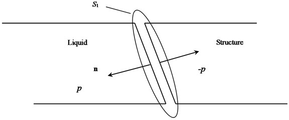
A part of the liquid boundary surface is assumed to be adjacent to the structure (Fig. 1), the boundary surface adjacent to the structure is represented as , and the force acting on structure boundary caused by liquid pressure can be obtained by Eq. (8) [16]:
where is liquid movement velocity perpendicular to the boundary, is tangential velocity:
2.3. FSI equation
Because the system is non-linear, each exact solution needs multiple equilibrium iterations. Adding structure term into liquid motion of Eq. (5), then the FSI equation based on subsonic potential flow theory can be expressed as [16]:
where , and are mass, damping and stiffness matrix of structure; is load vector of structure.
Fig. 1Interaction of liquid and structure
Because Eq. (2) contains nonlinear item (Bernoulli effect), besides, the relations between density and enthalpy, pressure and enthalpy in Eq. (4) are also nonlinear, so Eq. (5) and Eq. (10) can reflect the nonlinear characteristics of liquid sloshing under resonance.
The Rayleigh orthogonal damping model is used for the damping of the governing equations; the model assumes that the damping matrix of the system is a combination of mass matrix and stiffness matrix:
where and are mass and stiffness damping coefficients; and are the first and the second order circular frequencies, and the circular frequencies can be obtained by modal analysis based on Block Lanczos method; is damping ratio.
2.4. Boundary conditions
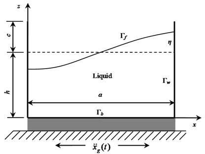
When the LSS is subjected to external excitation in the direction, which basically includes three kinds of typical boundary conditions (Fig. 2), namely, the wall boundary , the bottom plate boundary and the free surface boundary . On the free surface boundary , dynamic and kinematic conditions should be satisfied. The boundary conditions and the initial conditions of the velocity potential function needs to satisfy can be expressed as follows:
where is wave equation on the liquid free surface; is gravity acceleration; is structure velocity; is the length of the structure along the external excitation direction.
Fig. 2Boundary conditions
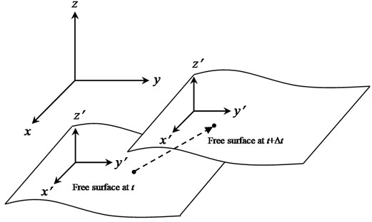
In order to better describe the mathematical problem, two Descartes coordinate system are defined, as shown in Fig. 3, one of which is assumed to be fixed in space, and the other is moved with the LSS [23]. For any quantity q to be solved can be expressed in any one of the coordinate system, namely, .
Free surface is the interface between the liquid and the atmosphere, and the interface will be affected by the surrounding pressure and surface tension. In the fixed Descartes coordinate system, the kinetic and dynamic boundary conditions on the free surface are [23]:
where is vertical coordinate of free surface.
Fig. 3Schematic diagram of movement of liquid free surface
Because horizontal displacement of sliding isolation LSS is large, the moving coordinate for solving the problem will bring significant convenience; free surface boundary condition in the fixed coordinate system can be expressed as Eq. (14) and Eq. (15) in the moving coordinate system [23]:
In the moving coordinate system, the potential function is composed of two parts: and , which are caused by the motion of the structure and the interior liquid sloshing:
Taking Eq. (18) into Eq. (16) and Eq. (17):
where is LSS displacement vector.
Then the initial boundary value problems of liquid sloshing in the moving coordinate system can be obtained:
3. Numerical example
3.1. Calculation model
The size of RLSS is 6 m×6 m×6 m, the thicknesses of the wall and the bottom plate are 0.3 m. Elastic modulus of concrete is 3×10¹⁰Pa, Poisson’s ratio is 0.2, density is 2500 kg/m3, tensile strength is 2.01 MPa [24], and 3-D Solid element is used for the concrete. Diameter of rebar is 12 mm, the spacing is 200 mm, the other parameters are shown in Table 1, bilinear elastoplastic model is used for the rebar. Potential-based fluid material and subsonic potential-based element are used to simulate the liquid, liquid density is 1000 kg/m3, liquid bulk modulus is 2.3×10⁹ Pa. The thickness of isolation layer is 0.3 m, 3-D Solid element is used to simulate the isolation layer, Mooney-Rivlin super elastic constitutive model is used for rubber isolation layer [25-27], and the strain energy density function described by the invariant of deformation tensor can be expressed as:
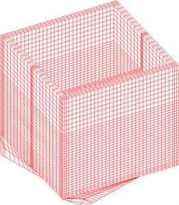
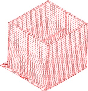
where is material constants generally determined by experiment; is deformation tensor invariant. Material constants of Mooney-Rivlin are shown in Table 2. Considering FSI, the calculation model of the base-isolated concrete RLSS is established [28], as shown in Fig. 4.
Table 1Parameters of rebar
Parameters | Elastic modulus / Pa | Density / kg / m3 | Poisson’s ratio | Initial yield strength / MPa | Strain hardening modulus / Pa | Max. allowable effective plastic strain |
Values | 2×10¹¹ | 7800 | 0.3 | 300 | 1×10⁹ | 0.0375 |
Table 2Material constants of Mooney-Rivlin (N/m2)
206000 | 1858 | 4100 | 100 | 0 | 28.1 |
Fig. 4Calculation model of base-isolated concrete RLSS
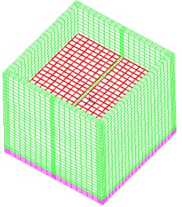
a) Whole model
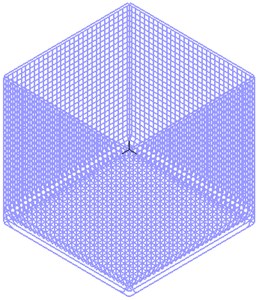
b) Rebar arrangement
3.2. Modal solution
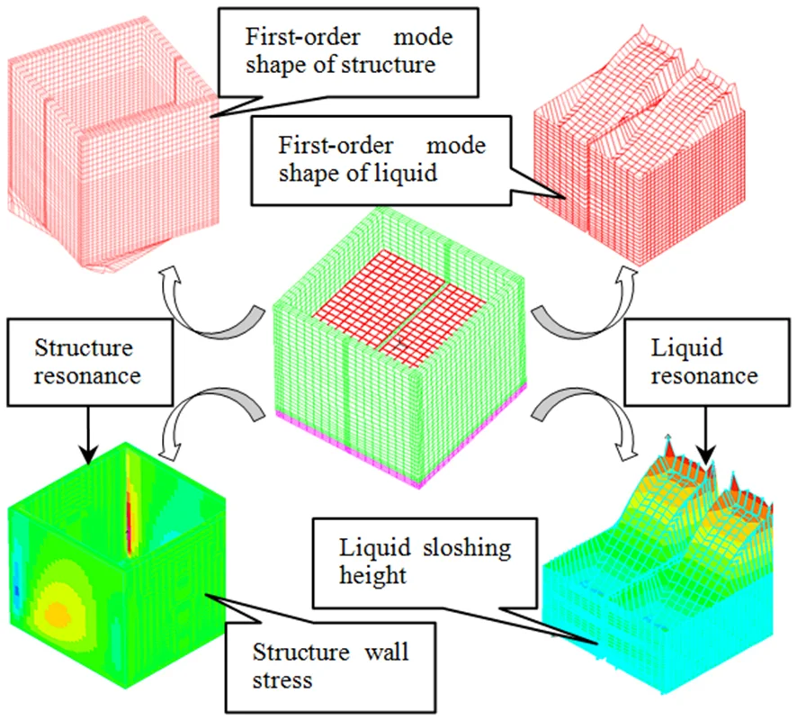
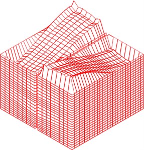
An important characteristic of LSS is that there are two kinds of vibration at the same time, namely, structure and liquid vibration, so there are two kinds of cycles in the system. Structure or liquid resonance will occur according to the external excitation. In order to obtain the structure and liquid frequencies and damping calculation coefficients, modal analysis is performed before resonance response analysis. The mode shape and frequency are shown in Fig. 5, Fig. 6 and Table 3.
Fig. 5Liquid vibration modes
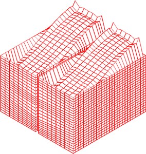
a) First order
b) Second order
Fig. 6Structure vibration modes
a) First order
b) Second order
Table 3Vibration frequencies of structure and liquid
Frequencies/ Hz | First order | Second order |
Structure | 2.444 | 2.937 |
Liquid | 0.3946 | 0.4361 |
3.3. Dynamic responses corresponding to the two kinds of resonances
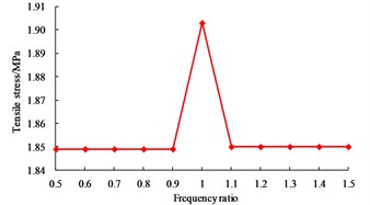
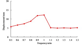
On the basis of the modal solution, taking the first order circle frequencies and of liquid and structure as the object, is used to simulate the harmonic function ( is amplitude, it equals to 0.1 g; is circular frequency; is time). The values of and are taken as 0.5, 0.6, 0.7, 0.8, 0.9, 1.0, 1.1, 1.2, 1.3, 1.4 and 1.5. Liquid resonance will occur when is equal to , and structure resonance will occur when is equal to . In order to study the influence of two kinds of resonances on dynamic responses, the maximum values of wall tension stress, structure displacement, base shear force and liquid sloshing wave height are analyzed. Dynamic responses of structure and liquid corresponding to two types of resonances are shown in Fig. 7 and Fig. 8.
As shown in Fig. 7, when the excitation frequency equals to the first order vibration frequency of structure, the tensile stress of the wall is 1.984 MPa, which is very close to the concrete tensile strength (2.01 MPa); however, when is equal to the other values, the difference of the wall tensile stress is not significant. When is equal to 1.0, the displacement of base-isolated RLSS reaches the maximum value 19.959 mm, at the same time, the base shear force also reaches the maximum value 2.677 kN. Besides, effects of excitation frequency on structure displacement and base shear force are basically the same.
Fig. 7Influence of structure resonance on dynamic responses
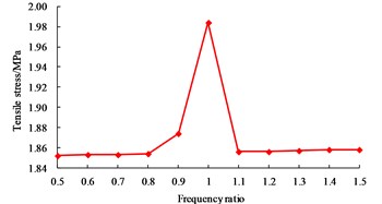
a) Wall tension stress
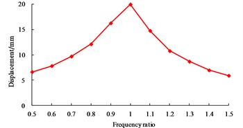
b) Structure displacement
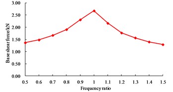
c) Base shear force
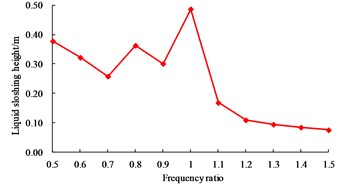
d) Liquid sloshing wave height
Fig. 8Influence of liquid resonance on system dynamic responses
a) Wall tension stress
b) Structure displacement
c) Base shear force
d) Liquid sloshing wave height
When is equal to 1.0, the liquid sloshing wave height reaches the maximum value 0.487 m; when is less than 1.0, the liquid sloshing wave height is still large; when is greater than 1.0, the liquid sloshing wave height is smaller, and the liquid sloshing wave height will be further decreased with the increase of excitation frequency. The main reason is that the liquid sloshing period is long, so smaller excitation frequency on the liquid sloshing wave height will be more significant. The vibration frequency of base-isolated RLSS is larger, when is greater than 1.0 and further increased, excitation frequency will be far away from the liquid sloshing frequency, so the liquid sloshing height is reduced.
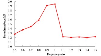
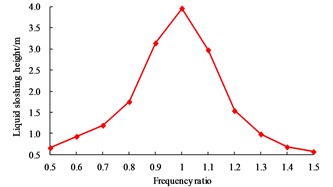
As shown in Fig. 8, when the excitation frequency equals to the first order vibration frequency of liquid, the tensile stress of the wall is 1.903 MPa, which is close to the concrete tensile strength (2.01 MPa); however, when is equal to the other values, the difference of the wall tensile stress is not significant. When is equal to 1.0, the displacement of base-isolated RLSS reaches the maximum value 12.300 mm, at the same time, the base shear force also reaches the maximum value 1.946 kN, and the effects of excitation frequency on structure displacement and base shear force are basically the same; when is equal to 1.0, liquid sloshing wave height reaches the maximum value 3.961 m, namely, which will occur obvious resonance amplification effect, and be easy to exceed the reserved no-water height, as a result, liquid overflow will happen. For LSS used to store chemical substances or pollutants, the consequences caused by liquid resonance will be more serious, so sufficient attention should be paid to this problem.
In order to further understand the influences of two kinds of resonances on dynamic responses of the system, the results of Fig. 7 and Fig. 8 are summarized. When the excitation frequency equals to the first order vibration frequency of base-isolated RLSS, the wall tensile stress, structure displacement and base shear force are obviously larger than that of liquid resonance; when the excitation frequency is equal to the first order vibration frequency of liquid, the sloshing height is far greater than of structure resonance. So, it is concluded that structure resonance has greater influence on the dynamic responses of structure itself, while liquid resonance has the greatest influence on the liquid sloshing.
Due to limited space, Fig. 9, Fig. 10 and Fig. 11 list the nephograms of wall tensile stress, liquid sloshing height and liquid velocity field.
Fig. 9Nephogram of wall tensile stress under resonance
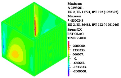
a) Structure resonance
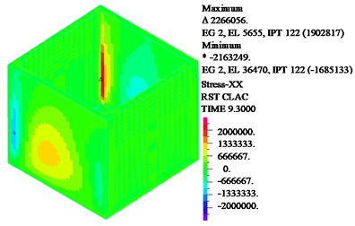
b) Liquid resonance
Fig. 10Nephogram of liquid sloshing wave height under resonance
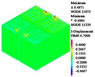
a) Structure resonance
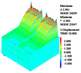
b) Liquid resonance
As shown in Fig. 9, when structure or liquid resonance occurs, the maximum tensile stress is located at the junction of the wall; in the design of structure, the cracking resistance can be enhanced by thickening concrete and adding reinforcement in these regions. As shown in Fig. 10, when structure resonance occurs, liquid sloshing height is small; the liquid sloshing height reaches the maximum value near the wall, the liquid height sloshing is basically equal to zero then the liquid is away from the wall. When liquid resonance occurs, the liquid sloshing height seriously exceeds the reserved no-water wall height. As shown in Fig. 11, when liquid resonance occurs, the liquid velocity field is very chaotic, which means the liquid movement is very violent.
Fig. 11Liquid velocity field under resonance
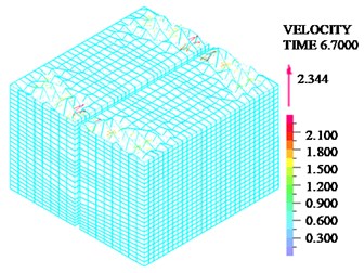
a) Structure resonance
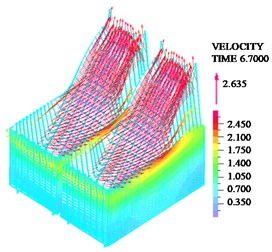
b) Liquid resonance
4. Conclusions
Subsonic potential-based fluid is used to simulate the nonlinear properties of liquid sloshing, and the FSI equation is established based on FEM. The representative dynamic responses (wall tensile stress, structural displacement, base shear force, liquid sloshing height and liquid velocity field) of base-isolated concrete RLSS are used as the analysis object, and the dynamic responses are comparatively investigated when liquid resonance or structure resonance occurs. The main conclusions are as follows:
1) When the external excitation frequency is equal to the first order vibration frequency of structure, wall tensile stress, structure displacement, base shear force and liquid sloshing wave height will suffer resonance amplification phenomenon, and the wall tensile stress is close to concrete tensile strength, as a result, wall cracking will be easily caused.
2) When the external excitation frequency is equal to the first order vibration frequency of liquid, wall tensile stress, structure displacement, base shear force and liquid sloshing wave height will also suffer resonance amplification phenomenon, and the effect of liquid resonance on liquid sloshing wave height is most obvious, which will easily cause liquid overflow.
3) Under the two kind of resonances, the maximum wall tensile stress all appears in the position of wall conjunction.
4) When liquid resonance occurs, the disturbance of liquid velocity field is obviously larger than that of structure resonance, which means liquid motion is more violent under this kind of resonance.
5) The influence of structure resonance on dynamic responses of structure itself is greater than that of liquid resonance, while the influence of liquid resonance on liquid sloshing is greater than that of structure resonance.
References
-
Kim N. S., Lee D. G. Pseudodynamic test for evaluation of seismic performance of base-isolated liquid storage tanks. Engineering Structures, Vol. 17, Issue 3, 1995, p. 198-208.
-
Chalhoub M. S., Kelly J. M. Shake table test of cylindrical water tanks in base-isolated structures, Journal of Engineering Mechanics. American Society of Civil Engineers, Vol. 116, Issue 7, 1990, p. 1451-1472.
-
Malhotra P. K. Method for seismic base isolation of liquid storage tanks. Journal of Structural Engineering, American Society of Civil Engineers, Vol. 123, Issue 1, 1997, p. 113-116.
-
Malhotra P. K. New methods for seismic isolation of liquid-storage tanks. Earthquake Engineering and Structural Dynamics, Vol. 26, 1997, p. 839-847.
-
Jadhav M. B., Jangid R. S. Response of base-isolated liquid storage tanks. Shock and Vibration, Vol. 11, Issue 1, 2004, p. 33-45.
-
Shrimali M. K., Jangid R. S. Seismic analysis of base-isolated liquid storage tanks. Journal of Sound and Vibration, Vol. 275, Issue 6, 2004, p. 59-75.
-
Ahmadi S. F., Eskandari M. Vibration analysis of a rigid circular disk embedded in a transversely isotropic solid. Journal of Engineering Mechanics, Vol. 140, Issue 7, 2013, https://doi.org/10.1061/(ASCE)EM.1943-7889.0000757.
-
Eskandari M., Ahmadi S. F., Khazaeli S. Dynamic analysis of a rigid circular foundation on a transversely isotropic half-space under a buried inclined time-harmonic load. Soil Dynamics and Earthquake Engineering, Vol. 63, 2014, p. 184-192.
-
Ahmadi S. F., Eskandari M. Rocking rotation of a rigid disk embedded in a transversely isotropic half-space. Civil Engineering Infrastructures Journal, Vol. 47, Issue 1, 2014, p. 125-138.
-
Ahmadi F., Samea P., Eskandari M. Axisymmetric response of a bi-material full-space reinforced by an interfacial thin film. International Journal of Solids and Structures, Vol. 90, 2016, p. 251-260.
-
Chen K., Zou D., Kong X., et al. Elasto-plastic fine-scale damage failure analysis of metro structures based on coupled SBFEM-FEM. Computers and Geotechnics, Vol. 108, 2019, p. 280-294.
-
Cho K. H., Kim M. K., Lim Y. M., et al. Seismic response of base-isolated liquid storage tanks considering fluid-structure-soil interaction in time domain. Soil Dynamics and Earthquake Engineering, Vol. 24, Issue 11, 2004, p. 839-852.
-
Shekari M. R., Khaji N., Ahmadi M. T. On the seismic behavior of cylindrical base-isolated liquid storage tanks excited by long-period ground motions. Soil Dynamics and Earthquake Engineering, Vol. 30, Issue 10, 2010, p. 968-980.
-
Sun J. G., Wang X. N., Zhao C. J. Theoretical study on seismic isolation of storage tanks. Journal of Harbin Institute of Technology, Vol. 42, Issue 4, 2010, p. 639-643.
-
Saha S. K., Matsagar V. A., Jain A. K. Comparison of base-isolated liquid storage tank models under bi-directional earthquakes. Natural Science, Vol. 5, Issue 8, 2013, p. 27-37.
-
Vosoughifar H., Naderi M. Numerical analysis of the base-isolated rectangular storage tanks under bi-directional seismic excitation. British Journal of Mathematics and Computer Science, Vol. 4, 2014, p. 3054-3067.
-
Angelis M. D., Giannini R., Paolacci F. Experimental investigation on the seismic response of a steel liquid storage tank equipped with floating roof by shaking table tests. Earthquake Engineering and Structural Dynamics, Vol. 39, Issue 4, 2010, p. 377-396.
-
Li Z. L., Li Y., Li H. B. Parametric research on seismic response of large scale liquid storage tank isolated by lead-rubber bearings. Journal of Sichuan University, Vol. 42, Issue 5, 2010, p. 134-141.
-
Yang Z. R., Shou B. N., Sun L., et al. Earthquake response analysis of spherical tanks with seismic isolation. Procedia Engineering, Vol. 14, Issue 11, 2011, p. 1879-1886.
-
Yang H. K., Gao B. Q. Parametric dynamic stability analysis and vibration isolation effect assessment of base-isolated liquid storage tanks. Journal of Vibration and Shock, Vol. 33, Issue 18, 2014, p. 96-101.
-
Cheng X. S., Jing W., Gong L. J. Dynamic responses of a sliding base-isolated RLSS considering free surface liquid sloshing. KSCE Journal of Civil Engineering, Vol. 22, Issue 12, 2018, p. 4964-4976.
-
Sussman T., Sundqvist J. Fluid-structure interaction analysis with a subsonic potential-based fluid formulation. Computers and Structures, Vol. 81, Issue 8, 2003, p. 949-962.
-
Cho J. R., Lee H. W. Non-linear finite element analysis of large amplitude sloshing flow in two-dimensional tank. International Journal for Numerical Methods in Engineering, Vol. 61, Issue 4, 2004, p. 514-531.
-
GB50010. Code for Design of Concrete Structures. China Architecture and Building Press, Beijing, 2010, (in Chinese).
-
Wei W., Tao D., Shugao Z. Determination for material constants of rubber Mooney-Rivlin model. Special Purpose Rubber Products, Vol. 25, Issue 4, 2004, p. 8-10.
-
Huang J. L., Xie G. J., Liu Z. W. FEA of hyperelastic rubber material based on Mooney-Rivlin model and Yeoh model. China Rubber Industry, Vol. 55, Issue 8, 2008, p. 467-471.
-
Yuan L. Finite element analysis of slab rubber bearings for building vibration isolation. World Rubber Industry, Vol. 6, 1993, p. 35-43, (in Chinese).
-
Cheng X. S., Liu B., Cao L. L., et al. Dynamic response of a base-isolated CRLSS with baffle. Structural Engineering and Mechanics, Vol. 66, Issue 3, 2018, p. 411-421.
About this article

This paper is a part of the China Postdoctoral Science Foundation (Grant No. 2018M633652XB), a part of the National Natural Science Foundation of China (Grant No. 51708270), a part of the Hongliu Outstanding Young Talents Support Program of Lanzhou University of Technology (Grant No. 04-061807) and a part of the Plan Project of Science and Technology in Gansu Province (Grant No. 144GKCA032).
