Abstract
The lift leveling mechanism provided in this paper is controlled by the special rope fastening. By using the lift leveling mode controlled by the rope fastening, the leveling mode of the lifting system can be changed to the braking stop of the drive system after the platform is lowered and placed on the bracket. The problem of anchorage precision and the vibration caused by elastic expansion of the rope during platform loading and unloading are effectively solved by using the supporting function of the piers. In the process of studying this problem, we simplified a heavy-duty elevator system to form a simplified model that can be used for simulation research. The device provided in this article provides a new solution for the leveling of the heavy-duty lifting system, which not only ensures the leveling accuracy of the lifting platform during loading and unloading, but also effectively reduces the impact during leveling, which has a beneficial guiding effect on this type of equipment.
Highlights
- Analyzed data from various lifting equipment, gained a detailed understanding of their usage conditions, and identified the main reasons that affect leveling accuracy.
- Multiple solutions were proposed based on the analyzed reasons, and the advantages and disadvantages, cost-effectiveness, and feasibility of each solution were compared, ultimately determining the final direction of this plan.
- Multiple rounds of optimization design were carried out on the final plan, considering multiple aspects such as structure, materials, manufacturing and processing, installation and construction, to finally determine the final structure of the device, and verify its effectiveness through experiments.
1. Introduction
Elevators, stackers, and other types of mechanical equipment have high lifting heights, making it more difficult to control the leveling accuracy. A steel-wire rope is a mechanical device that has many moving parts working in tandem to help support and move an object or load. In the lifting equipment industry, a steel-wire rope is attached to a crane or hoist and is equipped with swivels, stirrups, or hooks. It can also be used to raise and lower elevators or as a means of supporting suspension bridges or towers. Steel-wire rope is the preferred lifting device for many reasons. Its unique design consists of several steel-wires that form individual strands stored in a spiral around the core [1]. If the steel-wire rope or chain of the suspended platform is too long, it will increase its elasticity, which is not conducive to stable docking of the platform. During the loading and unloading process, the sudden change in load on the platform resulting in unstable phenomena such as vibration on the platform during loading and unloading.
2. Composition
This article relates to rope fastening for a lifting system, which is a leveling method for elevators controlled by a dedicated rope fastening, as shown in Figs. 1-2.
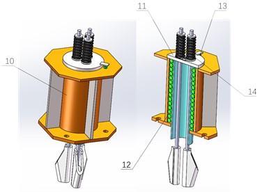
This device mainly consists of 10-14. The main spring and tension balance spring work together to ensure that the steel wire rope is always in a tensioned state during the leveling process, extending the leveling time, and ensuring that the platform's leveling accuracy does not change. This is one of the most obvious advantages of this device。
Below is a further explanation of the effectiveness of this article through the force conditions of each part.
The stress situation of each part is:
– The force on the steel-wire rope connecting counterweight is .
– The force on the steel-wire rope between the driving wheel and the lift platform is , the difference between and is balanced by the friction force on the driving wheel.
– The force on the steel-wire rope between rope fastening and lift platform is . Due to the fact that the pulley of the lifting platform is a movable pulley, .
– The supporting force of bracket on the platform is .
– The total weight of lifting platform and moving pulley is ; at no load and at full load.
Fig. 1Schematic diagram of working principle: 1 – rope fastening; 2 – steel-wire rope; 3 – movable pulley; 4 – lift platform; 5 – bracket; 6 – driving wheel;7 – counterweight
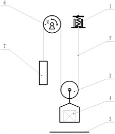
Fig. 2Structure diagram: 10 – mounting base; 11 – active plate; 12 – main spring; 13 – detection switch; 14 – tension balance spring
Consider a multi-strand wire rope, consisting of several strands that are wound around a core, and in turn each strand has a helical structure consisting of several wires. By treating each strand as a helix wire, the rope's mechanical behavior is just like a straight strand. The similar homogenization procedure was also adopted by (Costello, 1990) to get the mechanical characteristics of multi-strand wire ropes [2].
When a multi-strand rope is subjected to axial tension and torsion, each spiral strand undergoes not only tension and torsion along its centerline but also bending against the rope core. As the wires in the strand have been treated as a whole, the external deformation of the strand can be described by the kinematics parameters of its central wire [3].
As shown in the Fig. 1, before platform leveling, ; After leveling, .
Manufacturing error and installation error in the d lifting system are objective. The random parameters such as wire rope density, and elastic modulus existing in the lifting system cause the vibration of the HELS to be random vibration. The random vibration system not only affects the eigenvalues and eigenvectors of the various modes of the system, but also affects the statistical characteristics of the response [4]. In addition, studies have shown that when the initial conditions are consistent, the longitudinal vibration of the lifting system has a much greater impact on the system than the lateral vibration. Therefore, it is of great significance to study the dynamic response of the longitudinal vibration random parameters of the HELS on the elevator car vibration reduction, random parameter sensitivity analysis, and safety assessment. The establishment of the distributed parameter model of the HELS draws on the research theory of the axially moving string, which is simplified into a section of axial motion string with concentrated mass, which can better describe the flexible time-varying characteristics of the traction wire rope, so it is gradually being applied. Zhang et al. [5] simplified the elevator hoisting rope to a variable length axial motion string with a certain mass attached to one end, the differential equations and energy equations for the vertical vibration of the HELS were established by the energy method and the Hamilton principle. Bao et al. [6, 7] used the Hamliton principle to construct a lateral vibration control equation for flexible wire rope without external excitation and external excitation, and evaluated the theoretical model through experiments, the experimental results well agree with the theoretical predictions.
Under the drive of drive wheel, the lifting platform falls at a constant speed. When the lifting platform does not contact the platform bracket, the weight of the lifting platform is pulled by the steel-wire rope. The braking distance of drive wheel is the gap between the active plate of the spring and the lower seat, where and are the minimum values throughout the entire process. Among them, is determined by the system response time and operating speed. In the most unfavorable working condition, which is the maximum , needs to meet the following conditions:
The difference between and the counterweight tension should not cause the steel-wire rope to slip on drive wheel. That is, when the spring extends , the difference between and the counterweight is less than the critical friction force of the wire rope driving wheel slipping.
Expressed as Eq. (1) and Eq. (2):
In addition, a force condition that needs to be met is that the spring force must be able to ensure that the control switch can be triggered after the platform contacts the support bracket, that is, the upper and lower seats of the spring can be separated. When the upper and lower seats of the spring are pressed tightly, the spring force cannot be greater than the tensile force of when the empty platform does not contact the bracket.
Expressed as Eq. (3):
The above calculations ignore the influence of acceleration on the force.
3. Determination of main parameters
In order to make this device work better, we should determine the appropriate spring parameters based on the system's own data. The parameters of the main spring and tension leveling spring are determined based on multiple factors such as the platform's travel distance during leveling, platform operating speed, etc.
During the leveling process, when the distance between the rope fastening support plate and the rope fastening support is set to , the position switch is triggered, and the lifting platform stops running. In theory, when the motor stops rotating, the inertia rope head combination support plate will continue to run for a very small distance .
In order to ensure the stability of the flat spring, the total displacement should be controlled within a small range. When the motor is running at the minimum allowable operating frequency of 2 Hz (taking AC three-phase asynchronous motor as an example, the rated frequency of the motor is 50 Hz), the crawling speed of the lifting platform is , and the relationship between the crawling speed and the rated speed is:
The response time of the braking system is , generally 300 ms; When the brake is applied, the braking acceleration of the counterweight is , and the total displacement is:
When the recovery amount of compression deformation of the flat spring is equal to (), the change in spring elasticity should not exceed 5 % of the internal force of the flat spring. Using a small spring stiffness can ensure normal operation even if there are electrical control errors.
According to Euler’s formula, after the leveling action is completed and the system comes to a standstill, it should meet the condition that the steel wire rope does not slip:
Based on the above formula, the stiffness , deformation , and force of the flat spring can be obtained, thereby further determining the other parameters of the main spring and tension balance spring.
Under no-load conditions, a certain pressure should be maintained between the lifting platform and the steel structure frame. In order to ensure the reliable existence of pressure, the positive pressure at each level column pin can be taken as 0.05 Pg. The total pressure of the four level column pins is , which is 20 % of the weight of the lifting platform:
Before starting the leveling action, the contact force between the active plate and the mounting base should be 0, and it is advisable to use a force greater than 20 % of the spring tension .
When the system is stationary before the leveling action begins, according to the balance conditions of the lifting platform, it needs to meet the following conditions:
When the system comes to a standstill after the leveling action is completed, according to the balance conditions of the lifting platform, it needs to meet the following requirements:
From the above analysis, it can be calculated whether and meet the requirements. If they do not meet the requirements, it is necessary to increase the weight of the lifting platform, recalculate the parameters of the leveling spring, and verify the forces and .
4. Simulation
For simulation verification, we simplified a lifting device using this device, as shown in Fig. 3.
Fig. 3Structure diagram: 21 – rope fastening; 22 – steel-wire rope; 23 – lift platform; 24 – driving wheel; 25 – counterweight
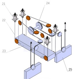
Table 1Basic size and style requirements
Parameter name | Value |
Rated speed of lifting platform | 1 m/s |
Rated load of lifting platform | 18.5 tons |
Equilibrium coefficient | 0.45 |
Flat spring stiffness | 40.8 N/mm |
According to the model in Fig. 4, the set lifting system parameters are shown in Table 1.
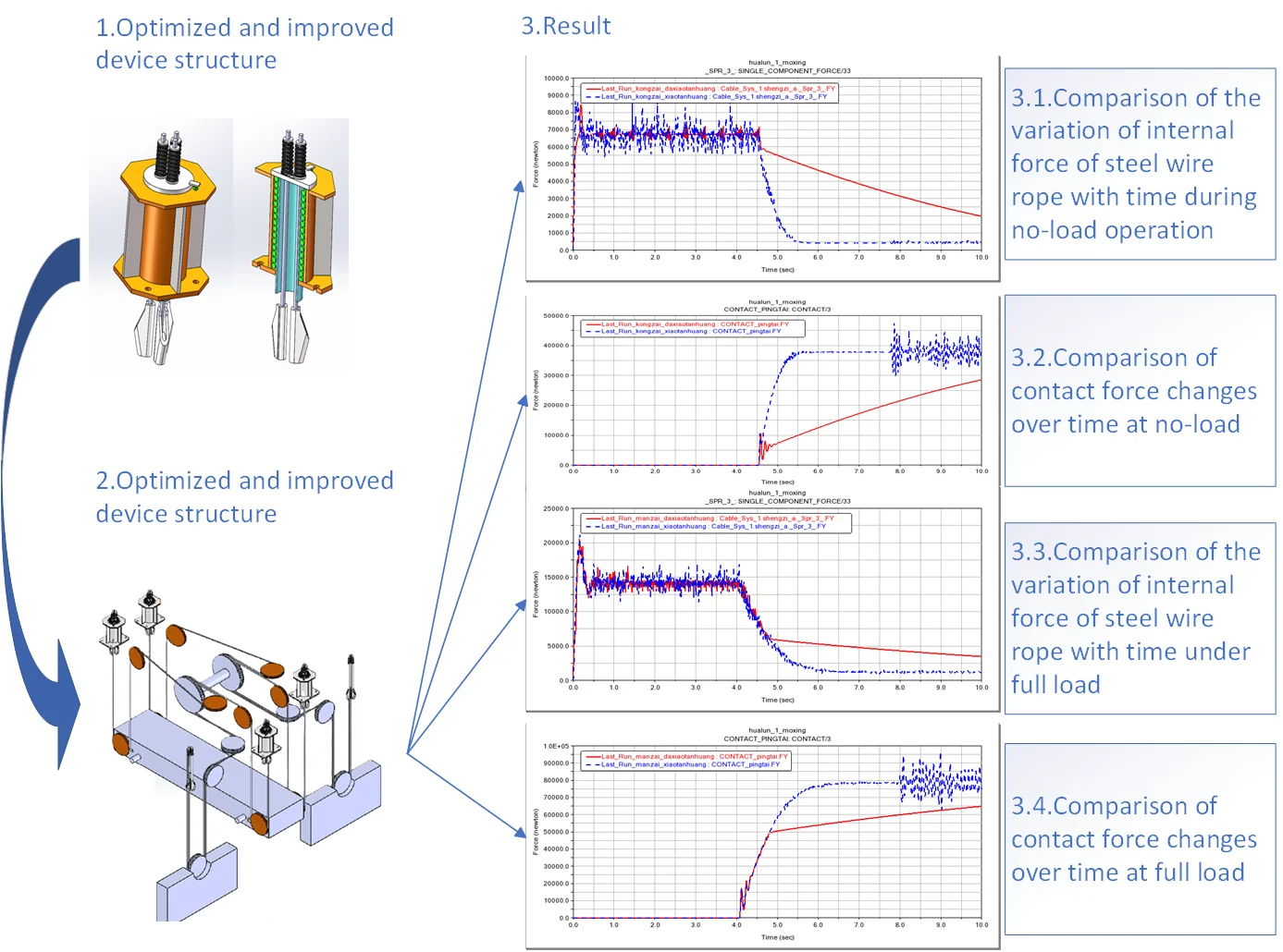
Before operation, the electrical leveling position of the lifting platform is set through the control system, usually set at a position higher than the final leveling position ( can be taken as 50-100 mm). The device described in this article was tested under two typical operating conditions, namely no load and full load. The blue dashed line represents the situation where the device is not applied, while the red solid line represents the situation where the device is applied, the test results are as follows:
1) No-load condition.
Fig. 4Comparison of the variation of internal force of steel wire rope with time during no-load operation
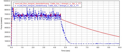
Fig. 5Comparison of the variation of internal force of steel wire rope with time during no-load operation
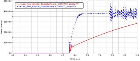
2) Full load condition.
Fig. 6Comparison of the variation of internal force of steel wire rope with time under full load
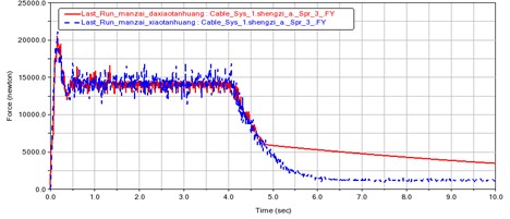
Fig. 7Comparison of contact force changes over time at full load
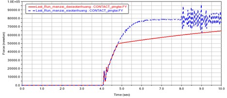
From the experimental results, it can be seen that without the use of rigid devices, regardless of the working condition, the internal force and contact force of the steel wire rope will change sharply in about 1 second. After the application of this device, the changes in the internal force and contact force of the steel wire rope become significantly slower, and this process is stretched to more than 4 seconds. Therefore, the electric control system has sufficient time to choose a suitable position to stop.
5. Conclusions
The lifting equipment leveling solution provided in this article has the following advantages:
1) Compared with conventional methods, this type of lifting equipment leveling method is limited by the bracket position, and the docking accuracy depends on the stiffness and position of the bracket, which is easy to ensure and has minimal error in repeated leveling positions.
2) The loading and unloading process of the platform is stable, with no sinking during loading and no rebound during unloading.
References
-
J. Hroncek et al., “Simplified numerical model for determining load-bearing capacity of steel-wire ropes,” Materials, Vol. 16, No. 10, p. 3756, May 2023, https://doi.org/10.3390/ma16103756
-
G. A. Costello, Mechanical Engineering Series. New York, NY: Springer US, 1990, https://doi.org/10.1007/978-1-4684-0350-3
-
L. Xiang, H. Y. Wang, Y. Chen, Y. J. Guan, and L. H. Dai, “Elastic-plastic modeling of metallic strands and wire ropes under axial tension and torsion loads,” International Journal of Solids and Structures, Vol. 129, pp. 103–118, Dec. 2017, https://doi.org/10.1016/j.ijsolstr.2017.09.008
-
W. Chen, Z. Ruijun, and Z. Qing, “Analysis of transverse vibration acceleration for a high-speed elevator with random parameter based on perturbation theory,” International Journal of Acoustics and Vibrations, Vol. 22, pp. 218–223, 2017.
-
Z. Peng and Z. Chang-Ming, “Analyses of longitudinal vibration and energetics on flexible hoisting systems with arbitrarily varying length,” Journal of Shanghai Jiao Tong University, Vol. 42, pp. 480–488, 2008.
-
B. Ji-Hu, “Dynamics modeling and vibration control of high-speed elevator hoisting system,” (in Chinese), Shanghai Jiao Tong University, 2014.
-
J.-H. Bao, P. Zhang, C.-M. Zhu, and W. Sun, “Transverse vibration of flexible hoisting rope with time-varying length,” Journal of Mechanical Science and Technology, Vol. 28, No. 2, pp. 457–466, Feb. 2014, https://doi.org/10.1007/s12206-013-1110-y
About this article

The authors have not disclosed any funding.
The datasets generated during and/or analyzed during the current study are available from the corresponding author on reasonable request.
The authors declare that they have no conflict of interest.
