Abstract
The dynamic distribution of contact stress of friction lining in the process of deep coal mine friction transmission was investigated in this study. Rope tensions during lifting and lowering were obtained using Simulink simulation models first. Then, correlation model of contact stress of friction lining was established. Subsequently, effects of the friction coefficient, lifting load, terminal mass ratio, maximum speed, maximum acceleration and acceleration rate on the dynamic distribution of contact stress were explored. The results show that the wrap angle of the friction pulley is divided into three, i.e. static, mixed, and friction angles, respectively. Furthermore, the friction angle decreases with the increasing coefficient of friction, and the increases of the terminal mass ratio induce expanding trends of overall ranges of the friction angle, which could result in rope skid accidents and unpredictable failure of friction lining.
1. Introduction
Friction hoist, which is driven by friction force between the friction lining and wire rope, is widely used in deep mine lifting (> 700 m). During friction lifting, the changing lifting rope length and inertial loads result in dynamic tensions of lifting rope [1, 2]. The rope with dynamic tensions wrapped around friction pulley result in elastic deformation of rope and dynamic contact stress on the friction lining. Different contact stress will lead to different friction coefficient which affect the friction force [3, 4]. The elastic deformation of rope result in elastic sliding on the friction lining [5, 6]. Therefore, the elastic sliding between the rope and friction lining has a relationship with dynamic contact stress on the friction lining. Elastic sliding and contact stress between the rope and friction lining is the necessary conditions of friction force. The elastic sliding area on the wrap angle is called the friction angle, and the rest of it is called the static angle [7, 8]. Meanwhile, excessive elastic sliding will result in rope skid accidents due to the insufficient friction force [9], which might cause the overwinding, overfalling and even cage falling. Therefore, it is of great significance to study the dynamic distribution of contact stress of friction lining and its correlation with the friction and static angles in the process of friction transmission.
In recent years, many scholars have performed extensive research on the friction behavior of wire rope and lining in friction hoist. Kaczmarczyk et al. [10] established a classical mathematical model to investigate the transient vibration phenomena in deep mine lifting ropes, and found that the dynamic tension and vibration of the wire rope is intense at the acceleration and deceleration stages, and the vibration frequency increases with the increasing wire rope length. Etsujiro et al. [11] presented a dynamic simulation of a wire rope involving contacts with a winch drum, and the simulation results show that some lever# operations result in rope looseness and intense pressure fluctuation. Martins and Shim et al. [12, 13] have pointed out that the majority of failure of pulleys are due to fatigue or overload failures, whereas Yao et al. [14] concluded that double rotational frequency of head sheave is the primary excitation frequency and rope tension can change the resonance frequency range, and assessment criteria for axial fluctuating displacements of head sheaves were finally established. Peng et al. [4] studied the effect of contact stress on the friction coefficient under low sliding speed and found that an increase in contact stress of lining within a certain range will increase the friction coefficient. Ma et al. [15] studied the sliding friction and wear properties of the friction lining under different contact stress, with friction-promoting grease applied, and found that grease can effectively reduce the lining’s wear and tear in the process of sliding with the wire rope, and the friction coefficient is still around 0.35. Ge et al. [3, 16] studied the relationship between friction coefficient and contact stress of the wire rope and the lining under dry, wet, and greasy conditions in the friction interface. The relational equation of contact stress and friction coefficient was established. The experimental standard of contact stress (1-3 MPa) for sliding contact between the wire rope and the friction lining was formulated. According to the aforementioned studies, most scholars studied the behavior of the wire rope and the lining with static and equivalent constant methods. This method were too simplified and can't reflect the real situation, especially the lack consideration of dynamic tension of the steel rope when defining the contact and friction parameters. However, few studies were conducted on the distribution of the contact stress of the friction lining on the friction pulley under the dynamic tension of the steel rope in the friction hoist.
This study aims to investigate the changing rule of dynamic distribution of contact stress of the friction lining during a lifting cycle. The distribution of the contact stress of the friction lining on the friction pulley reveal the lifting force and antiskid risk. Appropriate hoist parameters will help to improve the ability of the hoist equipment. The results also has guiding significance in the aspect of experimental parameters for the contact and friction between the rope and friction lining. The changing rule of contact stress of friction lining was utilized to reveal the distribution of the friction and static angles within the wrap angle. The corresponding simulation models were established to study the influence of lifting parameters on both the contact stress and the distribution of the friction and static angles.
2. Dynamic tension of lifting rope
2.1. Theory of dynamics of wire rope
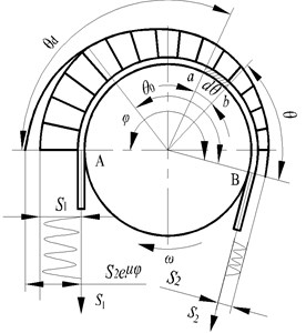
Fig. 1 is a schematic diagram of the multi-rope friction hoist. One side of the friction pulley lift full loaded container and the other side lower empty container. Friction lining is fixed around the surface of friction pulley. A number of ropes assembly in rope grooves on friction lining. When the friction pulley rotates in the clockwise direction, friction force between wire rope and liner driven the ropes lift the loaded container and lower the empty container, respectively. Assume the same friction force of each lifting rope and simplify all the ropes into a single one. Moving coordinates are located at tangent points A and B of the friction pulley with positive directions of coordinate axes pointing upwards and downwards, respectively. Differential equations of rope tension of tangent points A and B is written as [1, 17]:
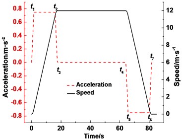
where is wire rope tension of point A () or point B (), N; is elastic modulus of wire rope, MPa; is sum of cross sections of all wires in a rope, mm2; is acceleration of gravity, 9.8 m∙s−2; is acceleration (as shown in Fig. 2), m∙s−2; is terminal mass, kg; is mass of the rope per unit meter, kg∙m−1; is mass of the tail rope per unit meter, kg∙m−1; is length of the rope between the container and the tangent points of friction pulley, m; length of the tail rope between the container and the guide pulley at the mine bottom, m; is lifting time, s; are change moment of acceleration (as shown in Fig. 2), s; is time from 0 to maximum acceleration, s.
Fig. 1Sketch map of the friction hoist
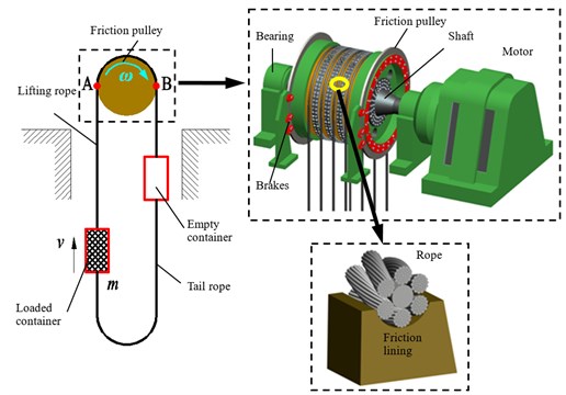
Fig. 2Acceleration and speed curves
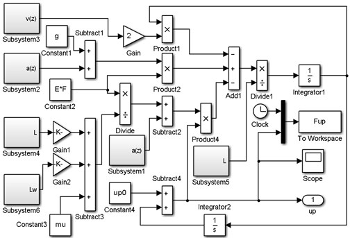
When the parameter contains the mass of container and minerals, according to the speed curve as shown in Fig. 2, is the rope tension of tangent point A. When the parameter contains the mass of container only and converts the speed of Fig. 2 to negative values, is the rope tension of tangent point B. The Rayleigh-Ritz method [7,9] is employed to deal with the lifting rope and tail rope that one third of which is added to . A simulation model is established by MATLAB-Simulink as Fig. 3 showed.
Fig. 3Simulation model of dynamic tension of the rope S
2.2. Simulation results of the dynamic tension of the rope
Simulink simulation results of the rope tension (points A and B) under the typical work condition (Table 1) are shown in Fig. 4. The rope tension fluctuates with increasing time and exhibits three stages that correspond to three lifting stages. At the acceleration stage of the lifting side, the rope tension value and amplitude reach the maximum; the maximum tension value is 1160.68 kN, and the maximum amplitude is 113.43 kN. At the acceleration stage of the lowering side, the maximum rope tension is 693.92 kN, and the maximum amplitude is 133.90 kN.
Table 1Parameters of the hoist system
Shaft parameters | Load mass (t) | 40 |
Container mass (t) | 50 | |
Lifting height (m) | 800 | |
Height from tangent point to lock port (m) | 30 | |
Multi-rope friction hoist | Type | JKM-4.6×6 |
Friction pulley diameter (m) | 4.6 | |
Wrap angle (°) | 195 | |
Safety factor of material lifting | 7 | |
Friction coefficient of the friction lining | 0.25 | |
Lifting rope | Type | 6×36WS+FC |
Diameter (mm) | 46 | |
Mass per meter of lifting rope (kg) | 8.52 | |
Minimum breaking force (N) | 1650 | |
Elastic modulus (MPa) | 105 | |
Number | 6 | |
Tail rope | Type | Flat rope P8×4×19+FC |
Size(mm) | 196×31 | |
Mass per meter of tail rope (kg) | 17.04 | |
Number | 3 | |
Kinematic parameters | Initial static tension of lifting side (N) | 9.55×10⁵ |
Initial static tension of lowering side (N) | 5.63×10⁵ | |
Maximum acceleration (m/s2) | 0.75 | |
Maximum speed (m/s) | 12 |
Fig. 4Rope tension at points A and B in the friction hoist
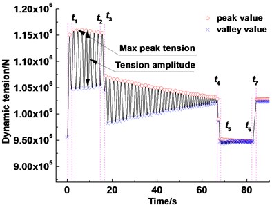
a) (Lifting side) Tension at point A
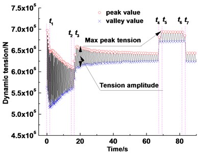
b) (Lowering side) Tension at point B
3. Dynamic distribution of contact stress of friction lining.
3.1. Theory of contact stress
Fig. 5 is an instantaneous distribution diagram of the rope tension on the friction pulley in the friction hoist. is the instantaneous rope tension of tangent point A at the lifting side, is the instantaneous rope tension of tangent point B at the lowering side, is the base of the natural logarithm, is the coefficient of the friction, moving coordinates are located at tangent point B on the friction pulley with positive directions of winding counterclockwise rotation. and are the friction angle and static angle within the wrap angle, respectively. A related study [18] has shown that the friction angle always appears at the side of separate point B, and the static angle appears at the side of meeting point A. When the tension difference increases between the two sides, friction angle increases to provide enough friction force.
Fig. 5Rope tension distribution in the instantaneous transmission in the friction hoist
The infinitesimal segment () of the wire rope (as shown in Fig. 5) is selected as the research object within the wrap angle. is the normal force between the rope and the friction lining on the infinitesimal segment, is the friction force, is the friction pulley radius, is the rope diameter, is the number of wire rope, and and are the tension of the two ends of the rope infinitesimal segment. Tension in the friction angle is distributed by Euler’s formula:
Compared with other forces, the centrifugal force is small enough to neglect. The instantaneous contact stress of infinitesimal segment of friction lining under the corresponding rope infinitesimal segment is:
The instantaneous distribution equation of contact stress of friction lining in friction angle can be obtained by substituting Eq. (2) into Eq. (3), i.e.:
The dynamic contact stress distribution equation in the friction angle between the wire rope and the friction lining can be obtained by substituting the rope dynamic tension of the lowering side into Eq. (4) as:
When the rope infinitesimal segment runs around the friction lining of the friction pulley from the meeting point A to the separate point B, the contact stress of the infinitesimal segment can represent the force distribution of friction lining on the entire wrap angle. As shown in Eq. (5), the contact stress is a function of not only position angle but also the time . Before the start of the lifting, the infinitesimal segment of the friction lining at meeting point A is selected as the target to be calculated. According to the above conditions, the angle of the infinitesimal segment at any time is:
where, is the clockwise rotation arc of the infinitesimal segment of friction lining. The point B is the coordinate starting point and changing circulatory within 0 to 2 on the friction pulley.
The static angle is close to meeting point A. Thus, according to Eq. (3), the distribution of contact stress can be represented as:
Fig. 6Simulation model of the distribution of the dynamic contact stress of friction lining in the friction hoist
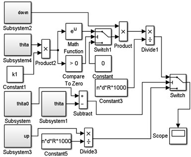
Fig. 7Submodel of friction angle θ0 within the wrap angle
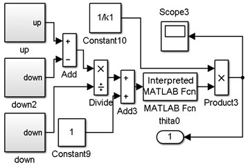
Fig. 8Submodel of counter-clockwise rotation angle θ within the circumference
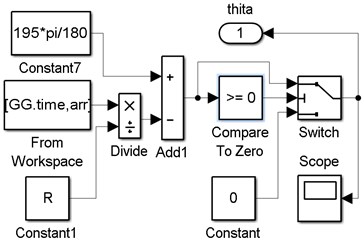
In order to obtain the distribution of the dynamic contact stress of the lining within the entire wrap angle on the friction pulley, a judge program is used to distinguish the friction angle and static angle. The distribution of the contact stress is governed by Eq. (5) when . By contrast, the distribution of the contact stress is governed by Eq. (7) when . The dynamic contact stress distribution simulation model of the friction hoist is obtained by MATLAB simulink (Fig. 6). Subsystem is the submodel of (Fig. 7), subsystems 1 and 4 are the submodels of (Fig. 8), and subsystems 2 and 3 are the rope tensions submodels of the lifting and the lowering side, respectively. The model can calculate the contact stress of the lining at any positions on the friction pulley.
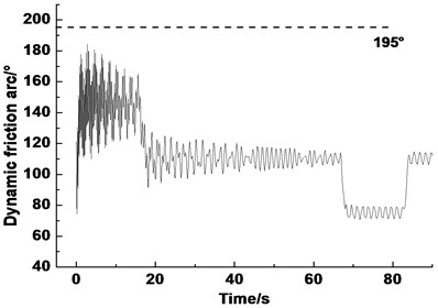
The dynamic variation of the friction angle in a lifting cycle is shown in Fig. 9. As shown in the Fig. 9, the dynamic friction angle shows different changing rules at the acceleration, constant speed, and deceleration stages. The amplitude of the angle in each stage is alternating. The peak value reaches 180° at the acceleration stage, but does not exceed 195° (wrap angle).
Fig. 9Dynamic angle θ0 in a lifting cycle in the friction hoist
3.2. Results and discussion
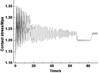
Fig. 10 shows the contact stress of the lining during the lifting. The contact stress of the lining reaches the maximum (1.8 MPa) at the acceleration stage. The maximum contact stress values of the constant speed and deceleration stages are around 1.65 and 1.5 MPa, respectively. The curve of contact stress according to the uniform model is shown in Fig. 11. The uniform model calculate the average pressure of the whole wrap angle of the friction lining on the pulley. The maximum contact stress is only 1.35 MPa. The calculated values are lower than the actual values:
Fig. 10Dynamic contact stress of friction lining during the lifting time
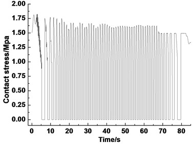
Fig. 11Dynamic contact stress of friction lining calculated by the uniform model
Figs. 12 show the contact stress of the lining at the acceleration, constant speed, and deceleration stage, respectively. The infinitesimal segment of friction lining separates from the wire rope when it rotates outside the wrap angle. Therefore, the contact stress curve appears as an inverted “U” type.
Fig. 12Dynamic contact stress of friction lining during different stages of lifting
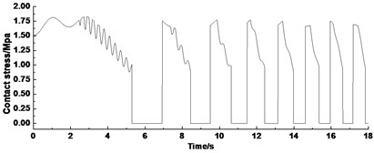
a) Acceleration stage
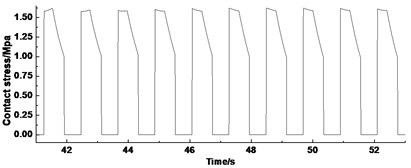
b) Constant speed stage
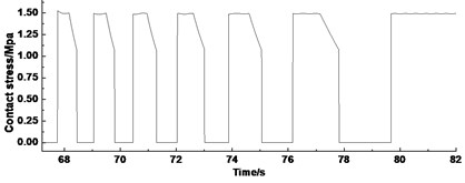
c). Deceleration stage
The first inverted “U” curve is captured from Fig. 12(a) (Fig. 13). The curve can be divided into three angles, i.e., A, B, and C, according to the characteristics. The alternating frequency is lower in angle A but higher in angle C. According to the reference [7], the wrap angle of the friction pulley is divided into friction angle and static angle in the statics analysis. So a determination method is proposed that the wrap angle of the friction pulley can be divided according to the dynamic contact stress of lining. Angle A belongs to the static angle on the friction pulley, the elastic sliding is not obvious in this area. The distribution of the contact stress depends on Eq. (7). The changing law depends on the tension . Angle C belongs to the friction angle on the friction pulley, and the elastic sliding of the wire rope is obvious in this area. The contact stress of the lining depends on Eq. (5). The changing law depends on tension . In addition, the changing law of the curve of angle B appears as the extending curve of angle A cuts off the peak of the curve of angle C. Thus, angle B is defined as the mixed angle on the friction pulley. The boundary of the static and friction angles changes in this area. The contact stress of the lining depends on Eqs. (5) and (7) at the same time. The elastic sliding between the wire rope and the lining appears intermittently. Through the method mentioned above, the angle size and the scope of the contact stress of the infinitesimal segment of lining are listed corresponds to Fig. 13 (Table 2).
Table 2Angle size and scope of the contact stress of the infinitesimal segment of the friction lining
Static angle | Mixed angle | Friction angle | |
Angle size / ° | 0-90 | 90-130 | 130-195 |
Scope of contact stress / MPa | 1.51-1.81 | 1.45-1.83 | 0.88-1.63 |
According to the reference [7], the friction angle provides a great majority of the friction force. So, as shown in Table 2, the angle that participates in the actual work on the friction pulley is from 90° to 195°. However, a large part of the previous angle did not make too much contribution to the supply of friction force.
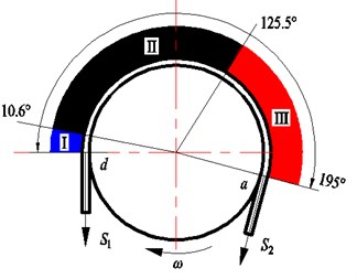
Due to the frequency characteristic is not as obvious as the first inverted “U” curve, the derivation method is used for each inverted “U” to find out the discontinuous point of curve. Fig. 14 shows the contact stress curve, the contact stress derivative curve, and rotating angle curve. The first discontinuous point of the contact stress curve can be observed through the derivative curve of each inverted “U”. The rotation angle that corresponds to this point is the first occurrence of the elastic sliding point 1 in Fig. 14(a). Prior to this point is the static angle. If the discontinuous point of each inverted “U” is found during the lifting, then the minimum static angle can be found by comparing the points. The minimum friction angle can be obtained in the same way point 2 in Fig. 14(b). Then two ultimate boundaries of the friction pulley can be obtained. Thus, the wrap angle can be divided into three ultimate a: I, II, and III. Angle I is defined as the minimum static angle, where elastic sliding is not obvious. Angle III is defined as the minimum friction angle, where elastic sliding always exists. Angle II is defined as the mixed angle, where elastic sliding intermittently appears (Fig. 15). After the comparison, we find that the boundary of the minimum static angle and the minimum friction angle are 10.6° and 125.5°, respectively.
Fig. 13Dynamic contact stress of friction lining when it rotated a wrap angle for the first time
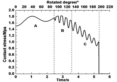
Fig. 14Derivative curve of the dynamic contact stress
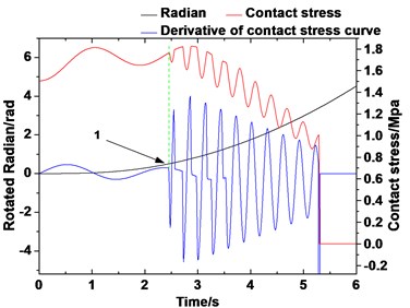
a)
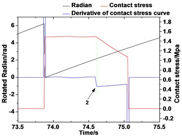
b)
Fig. 15Ultimate distribution of the dynamic contact stress
To characterize the difference of the size of the three angles and the contact stress values at different speed stages, the values are found out (Table 3).
As shown in Table 3, the friction angle and the contact stress range reach the maximum at the acceleration stage. The reason is that the dynamic tension is larger at acceleration stage. The friction force is sufficient to balance the tension difference on both sides of the friction pulley.
Table 3Angle size and contact stress values of each stage
Static angle / ° | Mixed angle / ° | Friction angle / ° | Maximum contact stress / MPa | |
Acceleration | 0-29 | 29-81 | 81-195 | 1.83 |
Constant speed | 0-70.5 | 70.5-100 | 100-195 | 1.64 |
Deceleration | 0-76 | 76-125 | 125-195 | 1.53 |
4. Influences of different lifting parameters on the dynamic distribution of contact stress of friction lining
The influence of different hoist parameters on the dynamic contact stress of friction lining is discussed from the aspects of different coefficients of friction, loads, and accelerations.
4.1. Different friction coefficients
Fig. 16 shows the contact stress of the infinitesimal segment of friction lining when it rotated from meeting point A to the wrap angle (195°). With the increase of the friction coefficient, the static angle becomes larger and the friction angle becomes smaller. A small friction angle can provide enough friction force to balance the tension difference on both sides of the friction pulley. In addition, the vibration of contact stress of the friction lining in the friction angle attenuates over time. This condition is due to the change in the contact angle as the infinitesimal segment approaching the separation point. This change reduces the force on the infinitesimal segment. Furthermore, the contact stress on the infinitesimal segment is lower in the wrap angle of the second half. And a small friction angle indicates a small range of elastic sliding between the friction lining and the wire rope. Then the wear of the wire rope and the friction lining can be reduced. However, this phenomenon will reduce the utilization rate of the friction lining because of the smaller effective working angle on the friction pulley.
Fig. 16Dynamic contact stress of friction lining under different friction coefficient
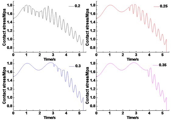
Fig. 17 shows the ultimate angle of the static angle, friction angle and the mixed angle under different friction coefficients during the whole lifting cycle. As the friction coefficient increases from 0.2 to 0.35, the minimum static angle increases from 0-1.1° to 0-93.4°, and minimum friction angle decreases from 27.5°-195° to 107.7°-195°. This phenomenon is consistent with the change in all angles of the infinitesimal segment at the meeting point mentioned above.
Table 4 lists the scope of the contact stress of the friction lining in three angles under different friction coefficients. It can be seen from the Table that the scope of the contact stress are different in the three angles, but there are not much obvious changing as the friction coefficients increases.
Fig. 17Ultimate angle of the static, mixed, and friction angles under different friction coefficient
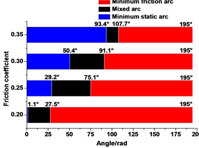
Table 4The scope of the contact stress of friction lining in three angles under different friction coefficients (MPa)
0.2 | 0.25 | 0.3 | 0.35 | |
Static angle | 1.48-1.75 | 1.48-1.81 | 1.48-1.83 | 1.48-1.83 |
Mixed angle | 1.5-1.79 | 1.45-1.83 | 1.50-1.81 | 1.50-1.71 |
Friction angle | 0.88-1.79 | 0.88-1.67 | 0.88-1.65 | 0.88-1.7 |
4.2. Different lifting loads
Figs. 18(a) and 18(b) show the contact stress of the infinitesimal segment of friction lining when it rotates from meeting point A to the wrap angle (195°) under different lifting loads (under the terminal mass ratio 1.6) and different terminal mass ratios (under lifting load of 70 t), respectively. The terminal mass ratio is the ratio of mass at the end of the lifting rope and the lowering rope. Fig. 18(a) shows that the maximum contact stress of friction lining gradually increases as the lifting load increases. But it has a low effect on the distribution of the three angles. The friction angle decreases and the static angle increases a little, respectively. The changing law of the contact stress showed in Fig. 18(b) is contrary to Section 4.1. The reason is that the larger terminal mass ratio means the greater need of friction force. In addition, the terminal mass ratio has a small influence on the maximum contact stress of friction lining, and the influential value does not exceed 2 %.
Fig. 18Dynamic contact stress of friction lining under different lifting load
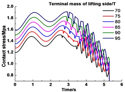
a) Different lifting loads
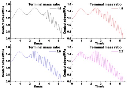
b) Different terminal mass ratio
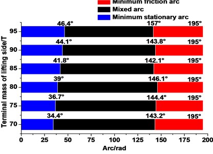
Figs. 18(a) and 18(b) show the ultimate angle of the static, mixed, and friction angles under different lifting loads (under terminal mass ratio of 1.6) and different terminal mass ratios (under lifting load of 70t) during the whole lifting cycle, respectively. Fig. 19(a) shows that the minimum static angle exhibits an increasing trend (34.4°-46.4°) with the growth in the lifting load. Furthermore, the minimum friction angle remains in the range of 143.2°–195°. Consequently, the mixed angle presents a declining trend. However, overall, the lifting load has a lower influence on all angles than the terminal mass ratio. Fig. 19(b) shows that the minimum static angle decreases significantly (from 0-34.4° to 0-0.6°), the minimum friction angle increases (from 143.2°–195° to 91.7°–195°), and the mixed angle decreases (from 34.4°–143.2° to 0.6°–91.7°) with the increase in the terminal mass ratio.
Fig. 19Angle of the static, mixed, and friction angles under different lifting load
a)
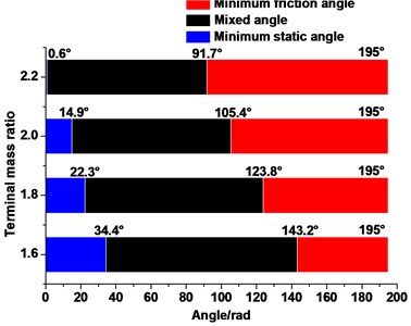
b)
Table 5 lists the scope of the contact stress of the lining in three angles under different lifting loads with the terminal mass ratio 1.6. It can be seen that the scope of the contact stress increase obviously as the lifting loads increases. The maximum contact stress disappears in the static angle (1.91 MPa) when the lifting load reached 95 t.
Table 5The scope of the contact stress of friction lining in three angles under different lifting loads (MPa)
70 t | 80 t | 90 t | |
Static angle | 1.21-1.5 | 1.35-1.67 | 1.48-1.83 |
Mixed angle | 1.26-1.5 | 1.36-1.66 | 1.50-1.81 |
Friction angle | 0.78-1.45 | 0.88-1.63 | 0.99-1.80 |
4.3. Different accelerations
Fig. 20 shows the dynamic changes of contact stress under different maximum accelerations with the maximum speed and acceleration rate remains unchanged. The contact stress peak decreases slightly with the maximum acceleration increases. Moreover, all the maximum values of contact stress are approximately 1.8 MPa. However, the maximum acceleration exerts a low influence on the distribution of the friction and static angles.
The acceleration rate exerts a low influence on the distribution of the friction and static angles (Fig. 21). But the maximum contact stress of friction lining has a special characteristic as the acceleration rate decreases. It can be seen from the first inverted “U” curve that the contact stress of friction lining which is larger in the mixed angle become smaller when it arrived in the friction angle. The contact stress of lining decreases (from 1.92 to 1.78 MPa) as the acceleration rate decreases (from 1.25 to 0.34 m/ s-3).
Table 6 lists the scope of the contact stress of friction lining in three angles under different acceleration rate with the maximum acceleration remains unchanged (0.75 m/s). As the acceleration rate decreases, the scope of the contact stress increases in the friction angle. Some researches has shown that the friction force increase as the static contact stress of lining increase within a certain range [15, 16]. And as we know from this paper, the major friction force come from friction angle and mixed angle. But a smaller acceleration rate will reduce work efficiency. Comprehensive consideration of friction force and the work efficiency, the relationship between the friction force and the dynamic contact stress need to be further studied with some experimental tests.
Fig. 20Dynamic contact stress of friction lining under different maximum accelerations
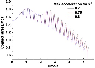
Fig. 21Dynamic contact stress of friction lining under different acceleration rate
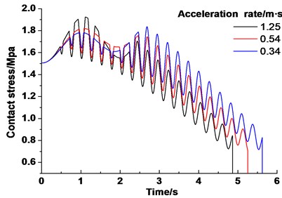
Table 6The scope of the contact stress of friction lining in three angles under different acceleration rate (MPa)
0.6 | 1.4 | 2.2 | |
Static angle | 1.5-1.65 | 1.5-1.74 | 1.5-1.73 |
Mixed angle | 1.41-1.92 | 1.41-1.82 | 1.42-1.84 |
Friction angle | 0.72-1.70 | 0.71-1.75 | 0.79-1.84 |
5. Conclusions
The dynamic tension values and tension difference of both sides of the friction pulley are obtained based on a simulation of real work condition of the hoist. The rope tension and the tension difference present a variation law with different amplitudes at different stages. In addition, the tension amplitude and amplitude variation reach a maximum level at the acceleration stage. With the help of these variation laws, the dynamic contact stress of friction lining and the distribution model are established. Model analysis determined that the contact stress on a certain point of the lining varies with the change in time within a wrap angle. Under the work condition in this paper, the maximum contact stress of lining can reach 1.9 MPa at the acceleration stage.
The calculation method is proposed that the wrap angle between the friction lining and the wire rope is divided into three angles, which corresponding to static, mixed, and friction angles, respectively. The range of each angle is evaluated: minimum angle (0-10.6°), mixed angle (10.6°-125.5°), and minimum friction angle (125.5°-195°). The peak of the contact stress of lining varies within the range of 1.5-1.8 MPa.
The influence of different hoist parameters on the dynamic contact stress of lining is analyzed. The analysis points out that static angle increases (from 0-1.1° to 0-93.4°) and the friction angle decreases (from 27.5°-195° to 107.7°-195°) with the increase of friction coefficient. Moreover, the maximum contact stress of the lining increases gradually (from 1.5 to 1.9 MPa) as lifting load increases (from 70 to 95 t). Furthermore, terminal mass ratio has a low influence on lining maximum contact stress (< 2 %). Minimum static angle decreases (from 0-34.4° to 0-0.6°), and minimum friction angle increases (from 143.2°-195° to 91.7°-195°) as the terminal mass ratio increases (from 1.6 to 2.2). In addition, the maximum contact stress of friction lining decreases (from 1.92 to 1.78 MPa) with the acceleration rate decreases (from 1.25 to 0.34 m/s-3) However, the lifting maximum acceleration, acceleration rate and the maximum speed have a low influence on the distribution of contact stress of lining (< 1 %).
References
-
Wang D. G., Zhang D. K., Zhang Z. F., et al. Effect of various kinematic parameters of mine hoist on fretting parameters of lifting rope and a new fretting fatigue test apparatus of steel wires. Engineering Failure Analysis, Vol. 22, 2012, p. 92-112.
-
Wang D. G., Zhang D. K., Wang S. Q., et al. Finite element analysis of lifting rope and fretting wear evolution and fatigue life estimation of steel wires. Engineering Failure Analysis, Vol. 27, 2013, p. 173-193.
-
Ge S. R. The friction coefficients between the steel rope and polymer lining in frictional lifting. Wear, Vol. 152, Issue 1, 1992, p. 21-29.
-
Peng Y. X., Zhu Z. C., Chen G. A. Effect of tension on friction coefficient between lining and wire rope with low speed sliding. Journal of China University of Mining and Technology, Vol. 17, Issue 3, 2007, p. 409-413.
-
Huang W., Liu H. X., Lian Y. S., et al. Modeling nonlinear creep and recovery behaviors of synthetic fiber ropes for deepwater moorings. Applied Ocean Research, Vol. 39, Issue 1, 2013, p. 113-120.
-
Kmet S., Mojdis M. Time-dependent analysis of cable nets using a modified nonlinear force-density method and creep theory. Computers and Structures, Vol. 148, 2015, p. 45-62.
-
Guo Y. B., Zhang D. K., Wang D. G. Theoretical modeling and variation law of dynamic friction angle of mining friction hoist. Journal of China Coal Society, Vol. 40, Issue 1, 2015, p. 2207-2212.
-
Lubarda V. A. Determination of the belt force before the gross slip. Mechanism and Machine Theory, Vol. 83, 2015, p. 31-37.
-
Wang D. G., Zhang D. K., Mao X. B., et al. Dynamic friction transmission and creep characteristics between lifting rope and friction lining. Engineering Failure Analysis, Vol. 57, 2015, p. 499-510.
-
Kaczmarczyk S., Ostachowicz W. Transient vibration phenomena in deep mine lifting cables. Part 1: Mathematical model. Journal of Sound and Vibration, Vol. 262, Issue 2, 2003, p. 219-244.
-
Etsujiro I., Takao N., Takahiro K. Dynamic simulation of wire rope with contact. Journal of Mechanical Science and Technology, Vol. 23, Issue 4, 2009, p. 1083-1088.
-
Martins J., Kovesdy I., Ferriera I. Fracture analysis of collapsed heavy-duty pulley in a long-distance continuous conveyors application. Engineering Failure Analysis, Vol. 16, Issue 7, 2009, p. 2274-2280.
-
Shim H., Kim J. Cause of failure and optimization of a V-belt pulley considering fatigue life uncertainty in automotive applications. Engineering Failure Analysis, Vol. 16, Issue 6, 2009, p. 1955-1963.
-
Yao J. N., Xiao X. M., Peng A. Assessment of safety for axial fluctuations of head sheaves in mine hoist based on coupled dynamic model. Engineering Failure Analysis, Vol. 51, 2015, p. 98-107.
-
Ma W., Zhu Z. C., Xu L. Sliding friction and wear properties of friction linings with friction-promoting grease applied. Proceedings of the Institution of Mechanical Engineers, Part J: Journal of Engineering Tribology, Vol. 228, Issue 6, 2014, p. 595-607.
-
Ge S. R., Xia R. H. Study on the friction drive equation of friction hoist. Journal of China Coal Society, Vol. 16, Issue 1, 1991, p. 51-63.
-
Wang D. G., Zhang D. K., Ge S. R. Effect of terminal mass on fretting and fatigue parameters of a lifting rope during a lifting cycle in coal mine. Engineering Failure Analysis, Vol. 36, 2014, p. 407-422.
-
Li J. S., Zheng W. G. Creep sliding and its measurement of friction hoist. Journal of Mining Machinery, Vol. 1, 1986, p. 16-22.
About this article

The research reported here was supported by the National Natural Science Foundation of China (Grant No. 51375479 and 51405489), Jiangsu College Postgraduate Research Innovation Plan Project of 2015 (KYLX15_1419), the Priority Academic Program Development of Jiangsu Higher Education Institutions (PAPD).
Yongbo Guo: main work of modeling, analysis, and writing. Dekun Zhang: overall arrangement, analysis, modify, proofread. Dagang Wang: assist in modeling. Yuan Liu: part of the translation. Cunao Feng: part of the translation.
