Abstract
Aiming at the problem of insufficient rigidity of the tool system and unbalanced radial force during deep hole machining, this paper designs a deep hole connector using the fluid dynamic pressure lubrication principle. The deep hole connector includes double-bridge strain gauges and tiltable tiles, which can increase the rigidity of the tool system by using the oil film support stiffness and offset the unbalanced radial force of synchronous detection by adjusting the oil film pressure in real time. First, the mathematical model of tiltable tile is established, the oil film thickness formula is derived, and the formula of oil film pressure is derived. Then, based on Fluent software, the fluid simulation of the deep hole connector is carried out. The simulation adopts a single-factor experiment method, and the change law of oil film pressure on tiltable tile is analyzed under different conditions, respectively. The results show that during deep hole machining, the oil film pressure can be adjusted by adjusting the parameters of workpiece speed, cutting fluid viscosity, tile tilt angle, and tile wrap angle, and then achieve the purpose of increasing the rigidity of the tool system and offsetting the unbalanced radial force.
Highlights
- This paper designs a deep hole connector with strain gauges and tiltable tiles and illustrates the principle of increasing tool rigidity and counteracting unbalanced radial forces in deep hole machining.
- In the process of deep hole machining, the choice of high workpiece speed, large cutting fluid viscosity, large tile tilt angle, and 75° tile wrap angle, a single tiltable tile will be subject to a more considerable oil film pressure, you can get a better effect of increasing the rigidity of the tool system and inhibit the occurrence of tool system chatter.
- In the process of deep hole machining, a fixed workpiece speed, cutting fluid viscosity, and tile wrap angle are selected to keep the tool system balanced and improve the machining quality of deep holes by changing the tile tilt angle in real-time so that the oil film pressure on the connector is offset by the detected unbalanced radial force.
1. Introduction
A deep hole is a hole with a length-to-diameter ratio greater than or equal to 5 [1]. As the toolbar of deep hole machining is limited by the hole diameter, the small diameter and large length of the drill bar cause poor rigidity and low strength, and because of the asymmetric structure of the deep hole tool, the unbalanced radial force is generated during machining, and vibration and ripple are easily generated during cutting, which affects the straightness and surface roughness of the deep hole [2].
In 1886, O. Reynolds analyzed the mechanism of the hydrodynamic pressure phenomenon and derived the differential equation describing the distribution of pressure oil film. Nowadays, some scholars gradually apply the theory of hydrodynamic pressure lubrication to deep hole machining. For example, Oezkayaet al. [3] studied the flow behavior and interaction of cutting fluids of specific viscosity to provide ideas for optimizing tool geometry. Woon et al. [4] proposed an optimized design method for gun drilling for drilling deep holes in nickel-based alloys by analyzing the coolant flow characteristics and rheological properties. Another scholar designed an intelligent drilling rod system for deep hole machining with tiltable tiles using the characteristics of multi-oil wedge bearings and obtained a patent for the invention [5].
In deep hole machining, scholars at home and abroad have researched increasing the rigidity of the tool system. Still, there are few types of research on dynamically counteracting the unbalanced radial force of the tool system. In this paper, to address these two problems, a deep hole connector is designed with strain gauges and tiltable tiles for deep hole machining. Using strain gauges to measure the unbalanced radial force of the deep hole tool system and the oil film pressure generated by the tiltable tile to offset it is proposed. The oil film pressure is investigated by equation derivation and fluid simulation.
2. Deep hole connector design and principle
2.1. Deep hole connector structure design
The deep hole connector designed in this paper is shown in Fig. 1, with the front end machined with internal threads for fixed connection with the existing deep hole drill bit and the rear end machined with external threads for fixed connection with the existing deep hole drill rod. The connector is installed with four double-bridge strain gauges and four tiltable tiles. The four double-bridge strain gauges are connected as two Wheatstone bridges. The dynamic data collector provides the input voltage and collects the output voltage signal. The four tiltable tiles can be tilted around the central axis, and the piezoelectric ceramic stack controls the tilt angle (referred to as tilt angle). This connector is suitable for machining with a rotating tool feed of the workpiece [6].
Table 1 shows the relevant structural parameters of the deep hole connector.
Table 1Structural parameters of the connector
Projects | Symbols | Numerical value |
Machining hole diameter / mm | 30 | |
Drill pipe outer diameter / mm | 26 | |
Number of double bridge strain gauges | 4 | |
Tiltable tile outer diameter / mm | 29 | |
Tile width / mm | 24 | |
Number of tiles | 4 |
2.2. Principle of increasing Tool system rigidity
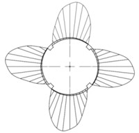
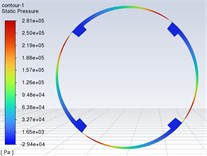
In the process of deep hole machining, four tiltable tiles are tilted to form a wedge gap with the workpiece wall at the same time, and the workpiece rotates at high speed to drive the viscous cutting fluid to flow from the large end to the small end, which meets the condition of forming dynamic oil film. The dynamic oil film produces equal oil film pressure on the surface of the four tiltable tiles, and the pressure distribution is obtained according to the one-dimensional Reynold equation, as shown in Fig. 2. Similar to a four-jaw chuck, it has the effect of increasing the rigidity of the tool system. The greater the oil film pressure generated, the greater the oil film support stiffness and rigidity.
Fig. 1Model of the connector with double-bridge strain gauges and tiltable tiles
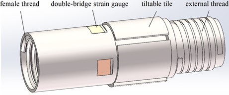
Fig. 2Tiltable tile and cutting fluid circumferential pressure distribution
2.3. Principle of counteracting the unbalanced radial force on the tool system
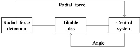
Fig. 3 shows the principle of the tool system to counteract the unbalanced radial force. Two Wheatstone Bridges composed of four double-bridge strain gauges measure the dynamic radial force generated by the front end of the tool system in two perpendicular directions, respectively. First, the radial force information is input to the control system, and then the control system controls the angle of the corresponding tilting block to change and form a wedge oil film with the hole wall. The wedge oil film generates an oil film pressure of equal magnitude and opposite direction to the radial force, which counteracts the unbalanced radial force of the tool system.
Fig. 3Schematic diagram of dynamic radial force adjustment system
After the derivation of the formula, the relationship between the radial force of the tool in the or direction and the output voltage of the Wheatstone Bridge is derived as:
where is the modulus of elasticity, is the input voltage, is the distance of the double-bridged strain gauge from the top of the tool, and is the internal diameter of the drill pipe. is the strain coefficient, the exact value specified on each strain gauge package. Typically, metal strain gauges have a strain coefficient of approximately 2.
, , , , and are known quantities, and the radial force of the tool can be obtained by collecting the output voltage signal through the data collector.
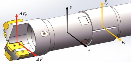
The forces on the tool system are shown in Fig. 4, which gives:
where , are the unbalanced radial forces in the and directions, respectively , and are , and direction and its offset oil film pressure.
In summary, the deep hole connector designed in this paper is used in deep hole machining to increase the system’s rigidity and counteract the unbalanced radial force. The study of the oil film pressure is the focus.
Fig. 4Schematic diagram of the force on the tool system
3. Analytical calculation of tiltable tiles subjected to oil film pressure
3.1. Oil film thickness formula
As shown in Fig. 5, the oil film gap function is , ignoring the deformation, the tiltable tile rotates around its midpoint , the rotation tilt angle is , the eccentricity of the tiltable tile center for the deep hole center is , the deep hole radius is , the tiltable tile radius is , and is the circumferential coordinate.
Fig. 5Oil film thickness diagram
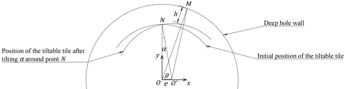
In , , then .
In , , then, can be obtained.
If the trace is omitted, and the positive sign of the root equation is taken, the oil film gap function at any position is obtained as:
3.2. Oil film pressure function
The classical Reynolds equation for one-dimensional flow is the basic equation for calculating fluid dynamic pressure lubrication and can be expressed as:
where is the oil film pressure; is the dynamic viscosity of the lubricant (N·s/m2); is the sliding speed (m/s); is the oil film thickness; is the oil film thickness at the maximum pressure.
From Reynold Eq. (4), we can see that the oil film pressure is related to influencing factors such as the viscosity of the lubricant, the sliding speed, and the thickness of the oil film.
According to the literature [7], we know:
where is the wedge-shaped oil film inlet clearance formed by the fluid; is the wedge-shaped oil film outlet clearance formed by the fluid.
Rewriting the Eq. (4) into polar form, i.e., substituting , into the above equation, the Reynolds equation in polar form is obtained as:
where is the relative rotational speed of the tool and the deep hole wall.
Integrating the pressure from the start angle to the end angle of the oil film, the total oil film pressure is obtained:
The final oil film pressure in the -axis direction is obtained as:
From the above formula derivation, it can be seen that the magnitude of the oil film pressure on the tiltable tile is related to the workpiece speed, cutting fluid viscosity, tile tilt angle, and tile wrap angle, and is proportional to the workpiece speed and cutting fluid viscosity. Therefore, by changing these parameters, the oil film pressure can be adjusted on the individual tiltable tiles and, thus, on the connectors.
4. Fluid simulation and results
By simulating the influence of different parameters on the tiltable tile subjected to cutting fluid oil film pressure, the simulation research is conducted by single-factor experimental method to analyze the change law of oil film pressure at different workpiece speeds, cutting fluid viscosities, tile tilt angles and tile wrap angles.
Table 2 shows the four levels corresponding to the four factors.
Table 2Factor level table
Level | Factor | |||
Workpiece speed (r/min) | Cutting fluid viscosity (Pa·s) | Tile tilt angle (°) | Tile wrap angle (°) | |
1 | 4250 | 0.048 | 1 | 65 |
2 | 5500 | 0.060 | 1.5 | 70 |
3 | 6750 | 0.072 | 2 | 75 |
4 | 8000 | 0.084 | 2.5 | 80 |
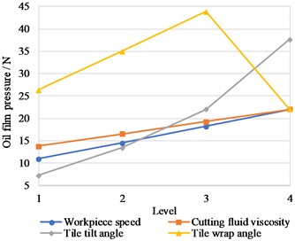
Based on Fluent software, a total of 16 sets of simulations were done for (1~4) 434, 4 (1~4) 34, 44 (1~4) and 443 (1~4). Figs. 6-9 show the pressure distribution clouds for the maximum oil film pressure in each factor. Fig. 10 shows the relationship between the oil film pressure and each factor.
Fig. 6Pressure cloud for workpiece speed of 8000 r/min

Fig. 7Pressure cloud for cutting fluid viscosity of 0.084 Pa·s

Fig. 8Pressure cloud for tile tilt angle of 2.5°
According to the above fluid simulation, we can obtain the following results:
(1) The oil film pressure on the tiltable tile increases with workpiece speed. The two are roughly proportional, and the cutting fluid viscosity is the same as the workpiece speed, consistent with the theoretical derivation.
(2) The oil film pressure on the tiltable tile increases with the tilt angle of the tile, but the relationship is not proportional.
(3) When the tile wrap angle is 65°-75°, with the increase of tile wrap angle, the oil film pressure on the tiltable tile increases proportionally. Conversely, when the tile wrap angle is 75°-80°, with the increase of the tile wrap angle, the oil film pressure of the tiltable tile decreases.
Fig. 9Pressure cloud for tile wrap angle of 75°
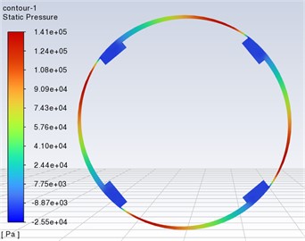
Fig. 10Result diagram of oil film pressure simulation
5. Conclusions
This paper designs a deep hole connector with strain gauges and tiltable tiles and illustrates the principle of increasing tool rigidity and counteracting unbalanced radial forces in deep hole machining. The equation of the tiltable tile subjected to oil film pressure is derived according to the one-dimensional Reynold equation, and fluid simulations with the one-factor variable method are conducted. The following conclusions were obtained by analyzing the results of the theoretical derivation and fluid simulation:
1) In the process of deep hole machining, the choice of high workpiece speed, large cutting fluid viscosity, large tile tilt angle, and 75° tile wrap angle, a single tiltable tile will be subject to a more considerable oil film pressure, you can get a better effect of increasing the rigidity of the tool system and inhibit the occurrence of tool system chatter.
2) In the process of deep hole machining, a fixed workpiece speed, cutting fluid viscosity, and tile wrap angle are selected to keep the tool system balanced and improve the machining quality of deep holes by changing the tile tilt angle in real-time so that the oil film pressure on the connector is offset by the detected unbalanced radial force.
References
-
J. Wang, Modern Deep Hole Machining Technology. Harbin Institute of Technology Press, 2005.
-
L. H. Chen, W. G. Wu, D. G. Yu, H. Y. Zhao, and A. D. Han, “Technological design of deep hole machining,” Tool Engineering, Vol. 56, No. 8, pp. 56–62, 2022, https://doi.org/10.3969/j.issn.1000-7008.2022.08.011
-
E. Oezkaya, S. Michel, and D. Biermann, “Experimental and computational analysis of the coolant distribution considering the viscosity of the cutting fluid during machining with helical deep hole drills,” Advances in Manufacturing, Vol. 10, No. 2, pp. 235–249, Jun. 2022, https://doi.org/10.1007/s40436-021-00383-w
-
K. S. Woon, G. L. Tnay, M. Rahman, S. Wan, and S. H. Yeo, “A computational fluid dynamics (CFD) model for effective coolant application in deep hole gundrilling,” International Journal of Machine Tools and Manufacture, Vol. 113, pp. 10–18, Feb. 2017, https://doi.org/10.1016/j.ijmachtools.2016.11.008
-
Z. Y. Chen, X. Q. Shen, Z. J. Xin, H. B. Miao, Z. Dong, and H. S. Zi, “An intelligent drilling rod system with radially tiltable tiles for deep hole machining,” CN108788238A, 2018.
-
S. X. Guan, G. Y. Fan, and X. Chang, “Study on key technology of deep-hole machining,” New Technology and New Process, No. 8, pp. 29–31, 2007, https://doi.org/10.3969/j.issn.1003-5311.2007.08.011
-
D. Yu, “Self-centering positioner and principle for locating and guiding deep-hole drills using oil films,” The International Journal of Advanced Manufacturing Technology, Vol. 92, No. 1-4, pp. 639–649, Sep. 2017, https://doi.org/10.1007/s00170-017-0185-5
About this article

This work is supported by the following grants: National Natural Science Foundation of China (52005456); Shanxi Province Patent Transformation Special Project (202305006); Special Project for Local Science and Technology Development (YDZJSX2022A032); XX Phase Change Characterization (2020-JCJQ-ZD-208-03-01).
The datasets generated during and/or analyzed during the current study are available from the corresponding author on reasonable request.
The authors declare that they have no conflict of interest.
