Abstract
This work studies the effect of lubricant inertia on the fluid cavitation for partially sealed high-speed squeeze film dampers (SFDs) executing small amplitude circular-centered orbits (CCOs). The lubricant cavitation is modeled by both the Elrod algorithm and the Gumbel’s cavitation boundary condition to provide the comparison between the most common lubricant cavitation models. Additionally, the fluid inertia is integrated by adapting a finite-length SFD model for partially sealed dampers. The integrated SFD model is incorporated into a numerical simulation model and the results are validated by comparison with experimental data. The results of the analysis demonstrate that the fluid inertia effects significantly extend the cavitation region and influence the cavitation onset and the film reformation.
1. Introduction
SFDs are specific lubricating elements that provide mechanical support and viscous damping in a rotordynamic system. The application of SFDs helps to solve the most commonly recurring vibration problems in practice by attenuating the vibration amplitudes of the rotor at critical speeds and reducing the likelihood of rotor instabilities [1]. However, SFDs in high-speed turbomachinery, including aircraft jet engines often endure severe conditions where the lubricant film is squeezed and ruptured rapidly, while providing the reaction forces to attenuate the steady-state unbalance induced vibration amplitudes.
The fluid cavitation has proven to significantly influence the damper dynamics, since not only the cavitation onset and extent determines the load capacity of a SFD, but also its presence influences the stability of a rotor-SFD system [2]. Consequently, the extent and the onset of the fluid cavitation are important parameters that should be carefully studied in the design and analysis of SFDs. The main challenge represented in the SFD lubricant cavitation studies are accurately computing the cavitation pressure and defining the cavitation boundaries. Conventional cavitation models assume no pressure gradient in the cavitation zone [3]. Accordingly, the lubricant cavitation pressure is assumed equal to the ambient pressure in case the SFD is exposed to open air, or it is assumed equivalent to the vapor pressure if the SFD is fully submerged in a lubricant reservoir. The accuracy of this assumption is debatable, since several experiments unveiled sub-ambient pressure or zero absolute pressure in the cavitation region [4-6]. Moreover, defining the cavitation boundary is of fundamental interest in modelling the cavitation phenomenon. The primitive Gumbel’s cavitation boundary condition sets the negative pressure values in the cavitation zone to zero. The Swift-Stieber boundary condition [7] has been widely applied to lubricant cavitation problems and the results demonstrate an acceptable agreement with experimental data. The Swift-Stieber boundary condition represents the flow continuity at the film-cavity interface, while it does not account for the downstream region of the cavitated lubricant volume. The Jakobsson-Floberg-Olsson (JFO) model [3, 8] is developed based on the continuity of mass flow and it provides accurate cavitation boundary conditions. However, this method is computationally inefficient especially for rotor-SFD applications. This computational deficiency problem is addressed by the Elrod cavitation algorithm [9]. According to the Elrod algorithm, the pressure distribution in both the full-film and the cavitated region are represented based on a single flow equation. This equation is iteratively solved to determine the pressure distribution for the two fluid regions.
Furthermore, the effect of lubricant inertia is generally neglected in the lubricant cavitation analysis. According to classical lubrication theory, the fluid pressure distribution in a SFD is determined by using the Reynolds equation, where it is assumed that the inertial forces are negligible relative to the viscous forces (i.e. 0) [3]. However, the demand for increased velocity and size of turbomachinery and application of low-viscosity lubricants require the fluid inertia effect to be included in the design and analysis of SFDs. In high-speed turbomachinery applications, the squeeze Reynolds number is typically between 1 and 50 [10]. Different theoretical studies have investigated the modeling and the formulating of the lubricant fluid inertia effects in SFDs. These theoretical studies provide different insights into the lubricant inertia, including: closed-form analytical solutions for the SFD fluid equations [11-13], numerical procedures to solve the SFD pressure distribution and reaction forces [14-18], the force coefficients that represent the direct and cross-coupled SFD inertia and damping [19-22], and SFD expressions for limiting damper geometries (i.e. long and short bearing approximations) [23, 24]. Nevertheless, these studies are accomplished in the absence of fluid cavitation effects or by incorporating simplistic π-film condition. Additionally, in experimental studies of fluid inertia effects in SFDs, the lubricant is supplied at sufficiently large gauge pressure to avoid lubricant cavitation. Contrarily, practical applications often endure cavitated lubricant flows in SFDs.
Theoretical and experimental studies that directly target the hydrodynamic pressure in SFDs are very limited when integrating the fluid inertia and the lubricant cavitation. For a partially sealed SFD, the long bearing approximation (LBA) [3] model is applied to determine the pressure distribution and the force coefficients [25]. This prediction is compared with the experimental data for validation [26]. However, the simulation model applies the Swift-Stieber boundary condition that does not demonstrate the requisite accuracy. Recent studies have incorporated the computational fluid dynamics (CFD) technique to solve the full-term Navier-Stoke equation for the fluid in SFD [27, 28]. In general, CFD provides a significantly accurate alternative technique as a baseline to evaluate the conventionally reduced SFD models. However, the CFD model is generally inapplicable for rotordynamic analysis of SFDs since it is computationally inefficient due to the large mesh resolution generated to accommodate the specific SFD geometry, where the film thickness is two orders of magnitude smaller than the film length.
This paper will explore the effect of lubricant inertia on the fluid cavitation by integrating a conventional fluid cavitation model with a lubricant inertia model. A partially sealed SFD under small amplitude CCOs is studied. Furthermore, a numerical technique is presented to discretize the integrated model equations by applying the finite difference method. The proposed numerical model is simulated to calculate the hydrodynamic pressure and the reaction force for validating against experimental results. Finally, a model sensitivity study is presented to illustrate the effect of fluid inertia on the film cavitation.
2. Numerical models
2.1. The fluid inertia model
Hamzehlouia and Behdinan [14] have developed an expression which represents the pressure distribution in finite length SFDs executing small amplitude motions in the presence of fluid inertia effects. For small amplitude motions of the journal center, it is assumed that the nonlinear convective fluid inertia components are negligible relative to the temporal inertia terms. Furthermore, assuming that the shape of the fluid velocity profiles is not strongly influenced by fluid inertia effect, the inertial terms in the flow equations are approximated by using the inertialess velocity profiles. Moreover, the average momentum technique is applied to the flow equations and the wall shear stress differences are approximated. The proposed dimensional pressure distribution expression is given as follows:
where is the pressure distribution in the absence of fluid inertia, which is characterized by the Reynolds equation [3].
For SFDs executing CCOs under small Reynolds numbers, the pressure profile is not significantly affected by the fluid inertia [14]; therefore, Eq. (1) can be organized as follows:
For moderate and large Reynolds numbers, the effect of the third order term on the right-hand side of Eq. (1) is negligible [16] and the equation is reduced to:
Assuming that the effect of fluid inertia is negligible (i.e. 1), Eq. (2) and (3) are reduced to the classical Reynolds equation for SFDs. Furthermore, Eq. (3) provides explicit functions of the Reynolds number for the fluid pressure.
2.2. The cavitation model
According to the preceding discussion, the Elrod cavitation algorithm provides a significant computational advantage over the alternative cavitation algorithms. Therefore, in order to maintain an acceptable computational efficiency, in this work, the Elrod algorithm is implemented. The Elrod cavitation algorithm includes the liquid bulk modulus and a switch function to solve the governing equation for the lubricant pressure distribution. The liquid bulk modulus is a prescribed constant parameter that describes the variation between the density and the pressure for a compressible fluid, which is defined by . Assuming that the relative density is defined with respect to the minimum density of the unruptured lubricant, the liquid bulk modulus can be further represented as . Additionally, the switch function is defined as follows to distinguish between the cavitated region and the full film region:
The direct integration of the bulk modulus expression and incorporation of the switch function yields the following expression for the pressure field in SFDs:
2.3. The integrated model
The proposed cavitation algorithm is subsequently integrated into the fluid inertia model. In the region of lubricant cavitation, the principle of mass conservation requires to be constant; consequently, the differential expressions on the right side of Eqs. (2) and (3) are zero in the cavitated region. In order to balance the equation, it is assumed that the pressure is constant in the cavitation zone and Eq. (4) is implemented into the left side of Eqs. (2) and (3). Consequently, two new governing equations satisfying both the full-film and cavitated film zones are developed, which account for SFD operation under small and moderate to large Reynolds numbers respectively:
2.4. Numerical method
The analytical solution for Eqs. (6) and (7) does not exist for arbitrary damper geometries, even when the cavitation effect is neglected. Therefore, a numerical procedure is proposed to solve these equations.
Firstly, the finite difference method is employed to discretize the equations. The relative density, switch function, and fluid thickness are discretized by using the backward difference approach. Subsequently, Eq. (6) is numerically discretized as follows:
where , and refer to the discretized variables in , and coordinates. Eq. (8) is rearranged as follows to solve for the pointwise relative density :
where:
The coefficients in Eq. (10) are given in Appendix A1.
Eq. (9) is iteratively solved for the interior points by applying the corresponding pressure boundary conditions and by using the Gauss-Seidel technique. The initial value of the interior points is adjusted to zero. The iteration is interrupted when the solution error reaches a prescribed convergence criterion. In order to accelerate the iterations, the successive over-relaxation (SOR) method is applied:
where denotes the relaxation factor, generally between 1 and 2. Once the point-wise density is computed, a correction procedure is proposed and incorporated into the switch function to address the cavitation phenomenon. According to the proposed correction, the switch function, initialized as 1in the absence of cavitation, is either updated to 0 if the corresponding relative density 1, or is updated to 1 if the corresponding relative density 1.
The iteration for Eq. (9) is repeated to find the pointwise relative density once the switch function is updated. The iteration and the correcting procedure are interrupted once a convergent solution is achieved. Additionally, Eq. (7) is discretized and numerically solved by using a similar procedure.
3. Simulation and validation
To ensure the validity and accuracy of the proposed method, a simulation model in MATLAB is developed. The results are compared with experimental data [26] in a case of a partially sealed SFD executing CCOs. In the experiment, the bearing executes whirling motions at 1770 rpm and the lubricant supply pressure is maintained at 68.95 kPa for both the top and the bottom axial feeding holes. Furthermore, the oil film temperature, the dynamic film pressure, and the SFD force coefficients are measured at different axial locations.
The CCO assumption for the motion of the SFD journal center reduces the pressure variation through the lubricant film to a steady-state problem with respect to the rotating coordinate system; as a result, the pressure profile can be determined at a particular whirling condition. Furthermore, the supply pressure is provided by two feeding holes, which represents the static pressure in the squeezed film, and together with the dynamic pressure described by the nontrivial solution of the governing equation demonstrates the total pressure in the SFD. Additionally, in order to address the circumferential boundary condition for the fluid pressure in the squeezed film, the Sommerfeld pressure boundary condition is applied [2], which assumes that the fluid pressure is equal to the supply pressure at the maximum lubricant thickness (i.e. 0).
Furthermore, in order to integrate the effect of lubricant leakage at the axial ends of the SFD, a seal coefficient factor [26] is incorporated into the pressure equation to represent the pressure gradient in the axial direction of the SFD as follows:
where is the lubricant pressure distribution based on the LBA and is the seal coefficient factor [19]. The detailed derivation of the LBA and the seal coefficient factor are respectively represented in Appendix A2 and Appendix A3.
Moreover, the radial and tangential components of the fluid film reaction forces are determined by integrating the pressure distribution over the journal surface as follows:
The proposed model is validated against the experimental data by comparing the cavitation length, the equivalent damping coefficient, the equivalent inertia coefficient and the film forces. In order to facilitate the direct comparison of the results, dimensionless parameters are defined as follows:
The detailed description of the SFD parameters in the simulations and the experiments is displayed by Table 1. The squeeze film Reynolds number for the experiments was calculated as follows:
Table 1Test SFD parameters in the simulations and the experiments
Parameter | Value | Unit |
0.0016 | m | |
0.1270 | m | |
0.0239 | m | |
68,950 | Pa | |
1,000 | Pa | |
0.00 | ||
0.18 | ||
0.0056 | m | |
0.0167 | m | |
69.000.000 | Pa | |
0.472 | ||
877.4 | Kg/m3 | |
0.1983 | Pa∙s | |
185.354 | Rad/s |
Table 2 shows the comparison between the simulation results based on the proposed model, the experimental results, and the simulation results based on the existing reference SFD models [19, 25]. According to the results, the simulations demonstrate a very close agreement with the experimental data in terms of the damping coefficient, the fluid film reaction forces, and the cavitation length.
Table 2Comparison between the simulations and the experimental results
Experiment [26] | Present model | Reference model [25] | Reference model [19] | |
Damping coefficient (Z1) | 19.03 | 19.30 | 17.91 | 11.80 |
Damping coefficient (Z2) | 18.48 | 18.86 | 17.50 | 11.35 |
Inertia coefficient (Z1) | –4.75 | –3.70 | –6.25 | –2.03 |
Inertia coefficient (Z2) | –4.64 | –3.62 | –6.10 | –1.95 |
Film force (Z1) | 9.26 | 9.27 | 8.95 | 5.65 |
Film force (Z2) | 9.00 | 9.07 | 8.75 | 5.44 |
Cavitation length | 113° | 114° | 108° | N/A |
The generated force and force coefficients from SFDs is of fundamental interest to study vibration when integrating this component into a rotordynamic system. If the force is too small, the SFD would be inefficient in reducing the large vibration amplitude; while if the force is too large, the SFD would act as a rigid constraint with large force transmitted to the supporting structure. In other word, insufficient modelling techniques would result in the inaccuracy of the force prediction and thus affects the vibration simulation of a rotor-SFD system.
The proposed model in this work provides a significantly more accurate prediction of the SFD behaviour relative to the existing reference SFD models. Moreover, the discrepancy between the inertia coefficient in the simulations and the experimental data can be justified since the damper eccentricity ratios in the experiments are slightly outside the small amplitude motion criterion, which is typically assumed for eccentricity ratios of 0.3, and consequently the effect of convective inertia terms increases the magnitude of the inertia coefficients. However, this discrepancy does not result in a disagreement between the magnitude of the forces in the simulations and in the experiments, since the effect of fluid inertia is only incorporated into the radial component of the reaction forces, while for small to moderate Reynolds numbers the magnitude of the tangential forces is significantly more dominant.
4. Discussions
This section represents a sensitivity analysis for the SFD parameters, including pressure profile, fluid film reaction force components, cavitation onset, film reformation, and cavitation length for the proposed model with respect to several operating conditions, including journal eccentricity ratios and the Reynolds number. In the simulations, the dimensionless pressure and fluid film reaction forces are calculated as follows:
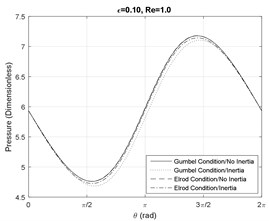
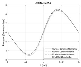
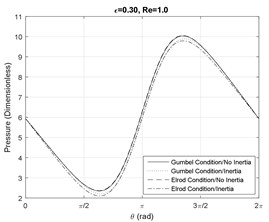
Figs. 1-3 represent the effect of SFD journal eccentricity ratio and squeezed film Reynolds number on the pressure profile at the axial mid-plane of the journal. In general, higher eccentricity ratios represent larger amplitude motions of the journal center, which result in larger magnitudes of the hydrodynamic pressure profiles, since the films is physically more tightly squeezed. For small Reynolds number, i.e. 1, the lubricant maintains the full-film status (i.e. no fluid cavitation).
Fig. 1Pressure profile at the SFD axial mid-plane Re= 1
a)
b)
c)
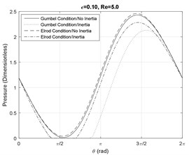
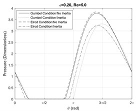
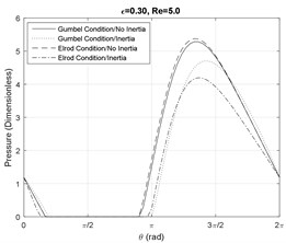
Fig. 2Pressure profile at the SFD axial mid-plane Re= 5
a)
b)
c)
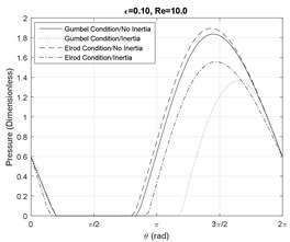
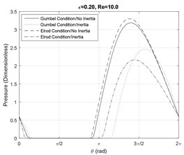
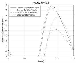
Furthermore, since at small Reynolds numbers the viscous forces are dominant, the effect of fluid inertia does no notably influence the shape and the magnitude of the pressure profiles. As the Reynolds number increases, fluid cavitation starts to appear and the divergences between the models become significant. Fig. 2(a) shows that at small eccentricity ratios and moderate Reynolds numbers, the fluid film is cavitated in the presence of fluid inertia effects. Furthermore, Fig. 2(a) and 3(a) illustrate that the Elrod model predicts a smaller cavitation region in comparison with the Gumbel’s model. This disagreement is smaller for larger damper eccentricity ratios based on the results in Figs. 2(b), 2(c), 3(b) and 3(c).
Fig. 3Pressure profile at the SFD axial mid-plane Re= 10
a)
b)
c)
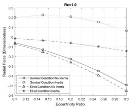
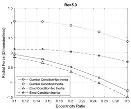
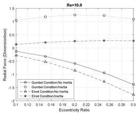
Figs. 4-5 represent the dimensionless radial and tangential components of the hydrodynamic forces generated by the squeezed film. This force is the reaction force that is applied on the journal to reduce the vibration amplitude of the rotor shaft and ensures the stability of the rotor system. In general, the radial components of the fluid film reaction forces are significantly dominated by the influence of fluid inertia effects. Even at small inertia effects, the magnitude and the direction of the radial forces is notably influenced by the fluid inertia effects. At moderate and large inertia effects, the fluid inertia effect reduces the magnitude of the radial forces and mitigates the likelihood of bistable operation of the rotor and instabilities.
Fig. 4Radial fluid film reaction force component
a)
b)
c)
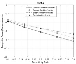
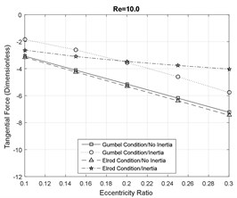
Fig. 5Tangential fluid film reaction force component

a)
b)
c)
Furthermore, the direction of the radial force components is changed in the presence of the fluid inertia effects. At smaller eccentricity ratios the forces are positive and the direction of the forces is inwards, however, at large eccentricity ratios, the direction of the forces eventually switch to outwards. Additionally, the magnitude of the radial forces suggested by the Gumbel cavitation boundary conditions is significantly larger than the Elrod conditions in the presence of the fluid inertia effects. Furthermore, the effect of fluid inertia is generally less significant on the tangential force components. At small Reynolds numbers, the results of the SFD models with and without inertia effects are in very close agreement. However, increasing the fluid inertia effects slightly reduces the magnitude of the tangential forces relative to the inertialess models.
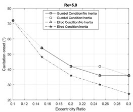
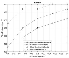
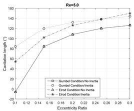
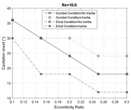
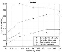
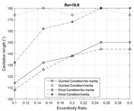
Figs. 6-7 represent the effect of fluid inertia on the fluid film cavitation at moderate and large Reynolds numbers. The inertialess models provide a close prediction of the SFD cavitation behavior. However, in the presence of fluid inertia effects, the Elrod model predicts an earlier onset of the cavitation than the inertialess models, while the Gumbel’s model predicts a delayed onset. Furthermore, the model including the inertia effects represent a delay in the film reformation with respect to the inertialess models. This delay is more significant for the Gumbel’s cavitation model. Additionally, the fluid inertia effects demonstrate a significant impact on cavitation length in SFDs by predicting a significantly more extended lubricant cavitation region. In general, at small eccentricity ratios, the Gumbel’s model predicts a larger cavitation zone relative to the Elrod model while this observation is reversed at large eccentricity ratios.
Fig. 6Cavitation analysis at Re= 5
a)
b)
c)
Fig. 7Cavitation analysis at Re= 10
a)
b)
c)
5. Conclusions
This work studies the effect of fluid inertia on the lubricant cavitation for partially sealed SFDs executing small amplitude CCOs. In order to compare the effect of different cavitation boundaries, both the Gumbel’s and Elrod cavitation models are incorporated into the analysis. Furthermore, a fluid inertia model is adapted for partially sealed SFDs for both small and moderate Reynolds numbers. The proposed integrated SFD model is numerically discretized and incorporated into a simulation model in MATLAB. Additionally, the simulation results are validated against experimental results in the literature, which have demonstrated excellent agreements. Finally, a sensitivity analysis of the proposed model at different journal eccentricity ratios and fluid inertia effects are represented. The results confirm the significant effect of fluid inertia on the cavitation onset, fluid reformation, and the length of the cavitation region.
The developed model is very efficient for incorporation into rotordynamic systems to analysis the unbalance-induced vibrations of high-speed rotors and it provides a reference for application and design of SFD in the turbomachine industry.
References
-
Adiletta G., Della Pietra L. The squeeze film damper over four decades of investigations. Part II: Rotordynamic analyses with rigid and flexible rotors. The Shock and Vibration Digest, Vol. 34, Issue 2, 2002, p. 97-126.
-
Brewe D. E. Theoretical modeling of the vapor cavitation in dynamically loaded journal bearings. Journal of Tribology, Vol. 108, Issue 4, 1986, p. 628-637.
-
Szeri A. Z. Fluid Film Lubrication: Theory and Design. Cambridge University Press, 2005.
-
Dede M. M., Dogan M., Holmes R. The damping capacity of a sealed squeeze film bearing. Journal of Tribology, Vol. 107, Issue 3, 1985, p. 411-418.
-
Zeidan A. Z., Vance J. M. Cavitation regimes in squeeze film dampers and their effect on the pressure distribution. Tribology Transactions. Vol. 33, Issue 3, 1990, p. 447-453.
-
Ku C. P., Tichy J. A. An experimental and theoretical study of cavitation in a finite submerged squeeze film damper. Journal of Tribology, Vol. 112, Issue 4, 1990, p. 40-44.
-
Swift H. W. The stability of lubricating films in journal bearings. Minutes of the Proceedings, Vol. 233, 1932, p. 267-288.
-
Hori Y. Hydrodynamic Lubrication. Springer Science and Business Media, 2006.
-
Elrod H. G. A cavitation algorithm. Journal of Tribology, Vol. 1, Issue 3, 1981, p. 350-354.
-
Arauz G. L., Andres L. S. Experimental study on the effect of a circumferential feeding groove on the dynamic force response of a sealed squeeze film damper. Journal of Tribology, Vol. 118, Issue 4, 1996, p. 900-905.
-
El-Shafei A., Crandall S. Fluid inertia forces in squeeze film dampers. Rotating Machinery and Vehicle Dynamics, Vol. 35, 1991, p. 219-228.
-
Tichy J. A. A study of the effect of fluid inertia and end leakage in the finite squeeze film damper. Journal of Tribology, Vol. 109, Issue 1, 1987, p. 1653-1675.
-
San Andres L., Vance J. M. Effect of fluid inertia on squeeze-film damper forces for small-amplitude circular-centered motions. ASLE Transactions, Vol. 30, Issue 1, 1987, p. 63-68.
-
Hamzehlouia S., Behdinan K. Squeeze film dampers executing small amplitude circular-centered orbits in high-speed turbomachinery. International Journal of Aerospace Engineering, Vol. 2016, 2016, p. 1-16.
-
Arghir M. Complete squeeze-film damper analysis based on the “bulk flow” equations. Tribology Transactions, Vol. 53, Issue 1, 2009, p. 84-96.
-
San Andrés L., Delgado A. A novel bulk-flow model for improved predictions of force coefficients in grooved oil seals operating eccentrically. Journal of Engineering for Gas Turbines and Power, Vol. 134, Issue 5, 2012, p. 52509-2.
-
Hamzehlouia S., Behdinan K. Squeeze film dampers executing small amplitude circular-centered orbits in high-speed turbomachinery. International Journal of Aerospace Engineering, Vol. 2016, 2016, https://doi.org/10.1155/2016/5127096.
-
Hamzehlouia S., Behdinan K. Linearized fluid film forces for squeeze film dampers executing small amplitude circular-centered orbits in aero-engines. 55th AIAA Aerospace Sciences Meeting, 2017, p. 1007.
-
San Andres, L. A., Vance J. M. Effects of fluid inertia on finite-length squeeze-film dampers. ASLE Transactions, Vol. 30, Issue 3, 1987, p. 384-393.
-
Tichy, J. A. Effects of fluid inertia and viscoelasticity on squeeze-film bearing forces. ASLE Transactions, Vol. 25, Issue 1, 1982, p. 125-132.
-
Reinhardt E., Lund J. W. The influence of fluid inertia on the dynamic properties of journal bearings. Journal of Lubrication Technology, Vol. 97, Issue 2, 1975, p. 159-165.
-
San Andres L. A., Vance J. M. Force coefficients for open-ended squeeze-film dampers executing small-amplitude motions about an off-center equilibrium position. ASLE Transactions, Vol. 30, Issue 1, 1987, p. 69-76.
-
Hashimoto H. Boundary conditions for the calculation of the dynamic characteristics of infinitely long journal bearings with turbulence and inertia effects. Wear, Vol. 96, Issue 1, 1984, p. 1-16.
-
Qingchang T., Wei L., Jun Z. Fluid forces in short squeeze-film damper bearings. Tribology International, Vol. 30, Issue 10, 1997, p. 733-738.
-
Jung S. Y., Vance J. M. Effects of vapor cavitation and fluid inertia on the force coefficients of a squeeze film damper. Part I: Analysis of a long SFD. Tribology Transactions, Vol. 36, Issue 4, 1993, p. 597-604.
-
Jung S. Y., Vance J. M. Effects of vapor cavitation and fluid inertia on the force coefficients of a squeeze film damper. Part II: Experimental comparisons. Tribology Transactions, Vol. 36, Issue 4, 1993, p. 700-706.
-
Xing C., Braun M. J., Li H. A Three-dimensional Navier-Stokes-based numerical model for squeeze-film dampers. part 1 – effects of gaseous cavitation on pressure distribution and damping coefficients without consideration of inertia. Tribology Transactions, Vol. 52, Issue 5, 2009, p. 680-694.
-
Xing C., Braun M. J., Li H. Damping and added mass coefficients for a squeeze film damper using the full 3-D Navier-Stokes equation. Tribology International, Vol. 43, Issue 3, 2010, p. 654-666.
Cited by
About this article

This research is supported by grants from Natural Science and Engineering Research Council (NSERC) and Pratt and Whitney Canada.
