Abstract
In order to analyze the influence of a damping ditch on the blasting vibration, a large number of on-site monitoring tests with or without damping ditch were carried out based on the foundation pit excavation project. Based on the Sadovsky’s empirical formula, the optimized vibration velocity attenuation model was established by using the waveform subsection correspondence method and least square method. The calculation results are in good agreement with the measurement results. The average errors in radial direction and vertical direction are 17.04 % and 10.76 % respectively. A series of finite element models were established to study the influence of the damping ditch geometry on the damping effect. The experimental and numerical results show that the damping ditch can obviously reduce the blasting seismic effect, with the highest damping ratio in the area near blasting source. For different damping ditches, the damping ratio first increases and then decreases proportionally to the increase of distance between the measuring point and the blasting zone. The damping ditch depth has the best damping effect on blasting vibration, followed by the distance between the damping ditch and the blasting source, and finally the damping ditch width, which is consistent with the damping mechanism of theoretical analysis. The attenuation of the surface wave is only related to the damping ditch depth. The research results can provide a reference for the design of blasting vibration isolation.
Highlights
- The optimized vibration velocity attenuation model was established by using the waveform subsection correspondence method and least square method.
- A series of finite element models were established to study the influence of the damping ditch geometry on the damping effect.
- The working mechanism of damping ditch was revealed from the theory of seismic wave propagation.
1. Introduction
Large-scale engineering projects such as important lifeline systems, large hydropower stations, and underground oil depots [1-3] both shall ensure the engineering quality during the construction process, and shall improve the construction speed. Because hard rock foundations are ideal for engineering projects, blasting excavation is inevitably used in the foundation excavation process. At present, the selection of parameters for blasting design mostly relies on experience and is closely related to formation lithology and topographic condition. Therefore, in order to meet the requirement of precise blasting control and reduce the impact of blasting vibration on adjacent structures, it is necessary to establish a blasting seismic wave attenuation model suitable for the site and set up vibration absorption measures on the basis of a large number of field tests [4-6]. It is necessary to establish a site-specific blasting seismic wave attenuation model and set up the vibration absorption measures on the basis of field tests.
The vibration absorption measures commonly used in blasting construction include controlling the maximum charge of a single blasting, selecting low-power and low-detonation explosives, and setting up a damping ditch and damping hole. However, the measures of reducing a blasting charge and changing the blasting method will affect the construction progress of a foundation pit, and the damping effect of a damping hole is obviously weaker than that of a damping ditch. The damping ditch can reduce the impact of blasting stress waves on the adjacent structures while ensuring that the construction progress remains unchanged. Many researchers have conducted a lot of studies on the blasting vibration attenuation model and on vibration isolation method intended for providing the damping effect [7-9]. Jayawardana et al. [10] investigated the effects of dual in-filled trenches with different geometry on mitigating ground vibration using the finite element method, and then presented an evaluation and prediction method of vibration mitigation using an artificial intelligence neural network. Bo et al. [11] studied the performance of wave barriers by establishing a series of 2D and 3D numerical models and developed an optimization design method to achieve the best vibration isolation effect. Alzawi and Naggar [12] conducted a full-scale field experiment to study the isolation efficiency of both open and in-filled trenches, and carried out an experimental verification and parameter analysis with a numerical simulation. Bose et al. [13] used 2D and 3D finite element models created in the PLAXIS software to investigate the influence of key parameters on vibration isolation efficiency of different trenches. Tian et al. [14] investigated the propagation law of blasting seismic waves caused by tunnel construction with a series of on-site monitoring tests and proposed a blasting vibration reduction scheme by reducing the vibration velocity and changing the main vibration frequency of blasting vibration. It can be concluded from the above literature that the blasting vibration attenuation law and the vibration isolation efficiency of the damping ditch are closely related to the topography and geological conditions of the engineering site [15-17]. In addition, the amount of monitoring data also has a large impact on the attenuation model, because the attenuation model is mainly the same as a statistical regression model. Therefore, for the area where blasting construction has not been carried out in history, it is necessary to create a vibration attenuation model for this specific area and develop a vibration reduction technology by the method of combining field monitoring and numerical simulation [18-20].
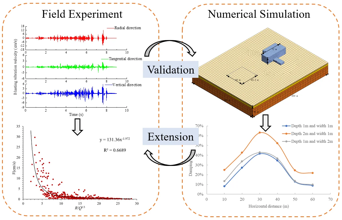
In this study, based on the blasting excavation project of underground powerhouse, a series of field monitoring tests of blasting vibration were carried out. A new data extraction method was proposed, and it can increase the amount of monitoring data. The optimized attenuation model of blasting vibration velocity suitable for the specific area was created on the basis of a large number of field monitoring data. The isolation effect of damping ditch on blasting seismic waves was studied by field monitoring and numerical simulation. Finally, the geometry analysis of the damping ditch was performed to determine the optimum barrier dimensions by the finite element method.
2. On-site monitoring of blasting vibration
2.1. Engineering Overview
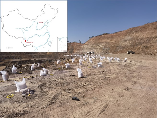
The test site is located in an underground powerhouse in the Southwest Yunnan province, China, as shown in Fig. 1. According to the requirements of negative excavation of foundation pit, it is necessary to carry out large-scale and multiple blasting excavation on the rock site. The total volume of earthwork is about 1.47 million cubic meters, and the loose blasting method is mainly used in the project. The medium-deep hole blasting technology is used for layered excavation in a large number of rock areas. The overall topography of the engineering site is high in the south and low in the north, and the overall terrain is relatively flat. The slope of the ground is about 3 % with slight fluctuation in some parts. The maximum elevation difference of the ground is less than 10 m, so it belongs to the slightly inclined landform. The thickness of overlying soil is about 1 m, and a rock stratum is located in the lower part. The upper part of the rock stratum is a strongly weathered layer, and the lower part is moderately weathered layer. The average thickness of strongly weathered rock layer is about 8.5 m, and the average thickness of moderately weathered rock layer is about 27.4 m.
The principle of on-site monitoring consists in that all working conditions shall have the same terrain conditions, same detonation method, and regular blasting areas. The reasonable design of blasting vibration monitoring is carried out based on these monitoring principles. A total of 16 blasting vibration tests, including 14 routine blasting vibration monitoring studies and 2 blasting vibration monitoring studies with a damping ditch, were completed.
Fig. 1Photo of engineering site in Southwest Yunnan province, China
2.2. On-site monitoring design
Traditional blasting was carried out on the site more than 20 times. Considering that each monitoring scheme is roughly the same, only the difference in the distance between the measuring point and the blasting zone does not affect the analysis of the monitoring results, so one of the conventional blasting schemes is taken as an example to illustrate. This blasting project uses tubular emulsion explosives, and the detonation method adopts the row-by-row delayed detonation. The relay detonator Ms5 (110 ms) is selected between rows. There are 22 rows of 445 blasting holes with a total depth of 3672.24 m in a foundation pit section, and the complete explosive weighs 9627 kg. The selection of blasting parameters and the calculation of charge amount are as follows: 1) the down-the-hole drill is used to construct a blasting hole with the diameter of 90 mm; 2) the 90 ° vertical hole is adopted for the blasting hole, and the average depth of the blasting hole is 7.5 m; 3) the density coefficient of vertical parallel holes is 1.2; 4) the minimum resistance line is 2.5; 5) the blasting hole spacing is 3.0 m, and the row spacing of blasting holes is 2.5 m; 6) the filling length is 2.7 m; 7) The unit consumption of explosive is 0.35 kg/m3, the charge quantity of each blasting hole () is calculated according to the rock blasting volume in each hole, 19.69 kg. The layout of monitoring points and blasting holes is shown in Fig. 2(a).
The location and width of damping ditch are determined according to the actual situation at the site. After the blasting excavation of a preset amount at the construction site is completed, when another blasting project will be carried out in the adjacent zone, the vibrometers can be placed at the other side of the blasting zone. This blasting zone is separated by an empty trench, so the influence of the damping trench on the attenuation law of blasting seismic waves can be assessed. According to the actual site conditions, the blasting vibration velocity monitoring of the damping ditch was completed twice in ditches of 36 m and 42 m wide respectively. The monitoring scheme with a width of 36 m is taken as an example to illustrate. There are 14 rows of 375 blasting holes in a foundation pit section, with a total depth of 2673.35 m and complete explosive weight of 6975 kg. The average hole depth is 7.1 m. The charge of each hole is 18.6 kg. The depth of the damping ditch is 7.5 m. The remaining blasting parameters are the same as those of conventional blasting. The row-by-row blasting is applied as the blasting method from north to south. The layout of blasting holes and monitoring points is shown in Fig. 2(b).
Fig. 2Layout of monitoring points and blasting holes
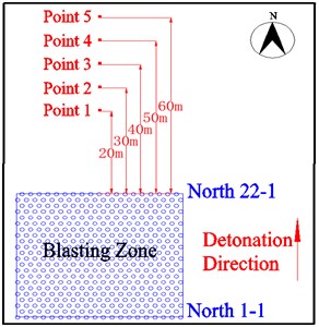
a) Conventional blasting monitoring
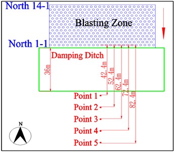
b) Blasting monitoring with a damping ditch
2.3. Monitoring instrument
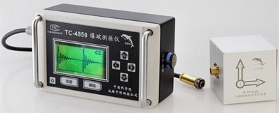
The instrument used in this test is tc-4850 blasting vibration meter, which is produced by China Zhongke Instruments Co., Ltd, as shown in Fig. 3. The sampling frequency of the sensor is 1 k - 50 ksps. The reading accuracy reaches 1 ‰, and the frequency response range is 5-500 Hz. The range of measurement is 0.001-35 cm/s. Firstly, before installing the sensor, the overlying soil covering on the ground surface shall be cleaned to expose the rock foundation. The vibration speed sensor is bonded to the rock foundation through calcined gypsum. Then, the horizontal bubble is adjusted to keep the speed sensor level. Finally, all sensors are installed in a straight line to keep the X direction pointing at the blasting center.
Fig. 3TC-4850 blasting vibration instrument
3. Analysis of field test results
3.1. Attenuation law of blasting seismic wave
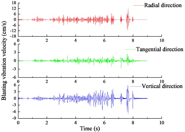
The time history curves of blasting vibration velocity at 30 m measuring point in one blasting project are shown in Fig. 4. The vibration velocity curves in the three directions of , and are arranged from top to bottom in this figure. The traditional empirical formula usually takes the maximum charge for simultaneous blasting (), corresponding vibration velocity () and blasting center distance () to regress the undetermined coefficient in the empirical formula. When the blasting method of row-by-row initiation is used, there is no unified criterion for the selection of vibration velocity and blasting center distance. The vibration velocity corresponding to the maximum charge could only be estimated by experience. Due to the influence of waveform superimposition, the absolute maximum value in the vibration velocity time history is often not caused by the maximum amount of explosives detonated at the same time. In addition, when the number of holes in each row of blasting zone is the same, and the charge quantity is basically the same, it is difficult to select the maximum charge quantity for simultaneous detonation. Therefore, the waveform subsection correspondence method is used to obtain the three known quantities in the Sadowski empirical formula, namely , and . The specific methods are as follows: 1) according to the characteristics of row-by-row detonation and fixed detonation interval (110 ms) in the blasting zone, the waveform is divided into several segments, and the number of segments corresponds to the number of detonation rows; 2) the maximum absolute velocity is found for each segment of the waveform, the detonation row number is determined corresponding to the speed according to the detonation time, and the distance is calculated from the measuring point to the detonation row; 3) , and belonging to the same row are set as a data array, so several arrays of data corresponding to the total number of detonation rows can be obtained, and all these data can be incorporated into the Sadowski formula for regression analysis. The method proposed in this paper both only clearly correspond to the charge quantity and waveform, which belong to the same row, and greatly increase the amount of data for regression analysis. The accuracy and reliability of the calculation formulas are significantly improved for empirical formulas with the use of essential statistical methods.
Fig. 4Time history curve of measured blasting vibration velocity
Due to that the blasting site is relatively flat, the elevation difference between the blasting zone and the measuring point is small during each monitoring, so the influence of the elevation difference can be ignored. Therefore, the Sadovsky empirical formula of particle vibration velocity can be used to establish the attenuation model of blasting vibration velocity [21]. This formula can be expressed as:
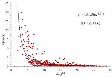
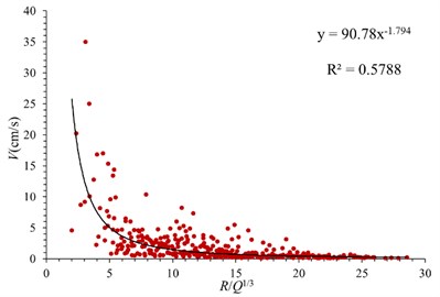
where represents the particle vibration velocity (cm/s); represents the charge quantity (kg); represents the distance from explosive source (m); is the site coefficient related to rock properties, blasting parameters and blasting methods. is the attenuation coefficient related to geological conditions. Fig. 5 shows the attenuation model of vibration velocity in three directions in case of conventional blasting. It can be seen that the vibration velocity in three directions decreases rapidly with the increase of proportional explosive charge (R/Q1/3). When the value of R/Q1/3 is less than 7, the attenuation rate of vibration velocity is obvious. When the value of R/Q1/3 is greater than 7, the attenuation gradually weakens, and finally tends to be gentle. The relationship between blasting particle vibration velocity and proportional explosive charge in three directions is obtained by least square regression. For hard rock formations, the reference value of is 50-150, and the reference value of is 1.3-1.5. The and values proposed in this paper are relatively close to the reference value. Due to the particularity of site conditions and stratum lithology, the proposed value is slightly larger than the reference value. The empirical formulas are as follows.
Radial direction, :
Tangential direction, :
Vertical direction, :
Fig. 5Attenuation law of blasting seismic wave in conventional blasting
a) Radial direction
b) Tangential direction
c) Vertical direction
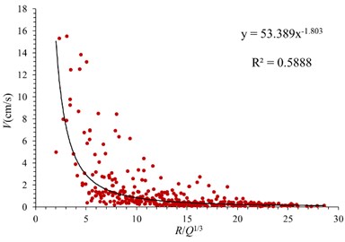
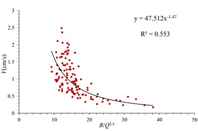
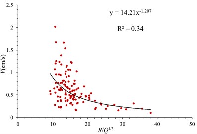
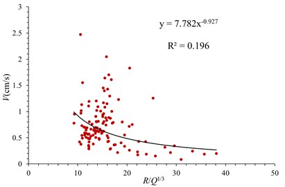
The attenuation law of blasting vibration velocity in case of using a damping ditch is shown in Fig. 6. The vibration velocities in three directions under the action of damping ditch also have power function attenuation characteristics in case of the increase of proportional explosive charge. When the R/Q1/3 varies from 10 to 20, the vibration speed decays fastest. The relationship between vibration velocity and proportional explosive charge in three directions is obtained by least square regression, which are shown as follows:
Radial direction, :
Tangential direction, :
Vertical direction, :
Fig. 6Attenuation law of blasting seismic wave under action of damping ditch
a) Radial direction
b) Tangential direction
c) Vertical direction
3.2. Analysis of damping effect of damping ditch
In order to verify the correctness and practicability of the blasting vibration velocity attenuation model proposed in this paper, a comparative analysis is carried out based on the blasting monitoring data of nearby sites. The adjacent blasting excavation zone having a total of 17 rows with 19 blast holes in each row adopts row-by-row detonation, and the explosive charge weight of each hole is 17.4 kg. One vibration meter is arranged 15 m away from the blasting zone, and the other vibration meter is arranged at 58 m. The comparison results of the calculated and measured blasting vibration velocity are shown in Table 1. The average error of the vibration velocity in the radial direction is 17.04 %, the one in the tangential direction is 52.41 %, and that in the vertical direction is 10.76 %. It can be seen that more accurate blasting vibration velocity can be obtained by using the waveform subsection correspondence method in the radial direction and vertical direction. Since the tangential direction is parallel to the detonation direction of the blasting zone, the accuracy of data collection will be affected, so the relative error in the tangential direction is relatively large. By comparing the radial velocity with the vertical velocity, it is found that there is a little difference between the numerical values of the vertical velocity and the radial velocity. Therefore, being a bit larger, vertical vibration will also affect the building structure near the blasting zone. Special attention should be paid to the vertical vibration speed in the vibration speed control.
Table 1Calculation results of blasting seismic wave velocity
Measuring point | Direction | Distance from explosive source / m | Calculated value / (cm/s) | Measured value / (cm/s) | Relative error / % |
1 | Radial direction | 20 | 18.634 | 16.682 | 11.701 |
Tangential direction | 8.953 | 15.326 | 41.583 | ||
Vertical direction | 15.359 | 18.219 | 15.697 | ||
2 | Radial direction | 65.5 | 1.773 | 1.449 | 22.386 |
Tangential direction | 1.042 | 0.638 | 63.236 | ||
Vertical direction | 1.807 | 1.708 | 5.817 |
Table 2Calculation values of vibration velocity with or without damping ditch
Measuring point | Distance from explosive source / m | Conventional blasting / (cm/s) | Damping ditch / (cm/s) | Damping ratio / % |
1 | 15 | 27.460 | 14.794 | 85.62 |
2 | 20 | 15.571 | 9.692 | 60.66 |
3 | 30 | 6.999 | 5.340 | 31.07 |
4 | 40 | 3.969 | 3.499 | 13.44 |
5 | 50 | 2.556 | 2.520 | 1.42 |
The vibration isolation effect of a damping ditch is studied by assuming blasting parameters and blasting zone. A certain blasting excavation zone having 15 rows with 20 blast holes in each row adopts row-by-row detonation, and the explosive charge of each hole is 15.6 kg. The measuring points are arranged at 15 m, 20 m, 30 m, 40 m and 50 m away from the blasting zone. Through the Eqs. (2) and (5), the vibration velocity values at the 5 measuring points with or without damping ditch can be calculated, as shown in Table 2. It can be seen that the damping ditch has an obvious damping effect, and the maximum damping ratio of the damping ditch is 85.65 %. When the blasting seismic wave passes through the damping ditch, the waveform conversion occurs, so the reflected stress wave, transmitted stress wave and diffracted stress wave are generated. Free surfaces at both sides of the damping ditch prevent from the propagation of the transmitted stress wave. In this experiment, the damping ditch is set up by using the site topography, the depth and width of the damping ditch are relatively large compared with the actual situation, which increases the propagation distance of diffracted stress waves. The energy of blasting seismic wave attenuates continuously with the increase of distance, so the calculated damping ratio is larger. The damping ratio of the damping ditch decreases with the increase of the distance from explosive source. In a certain distance, the effect of seismic isolation measures is obvious. When exceeding a certain distance, due to the obvious attenuation characteristics of the blasting seismic wave itself, the damping effect is not obvious.
4. Numerical simulation analysis
4.1. Creation of numerical model
In order to determine the reasonable size and the optimal location of the damping ditch, the first site blasting is used as a prototype to create a numerical analysis model for verification. According to the actual situation of the site, the MIDAS GTS/NX finite element software is used to create a full-scale numerical model. The length × width × height of the model are 300 m × 240 m × 40 m accordingly, as shown in Fig. 7. A factory building with a raft foundation is established to intuitively reflect the isolation effect of different damping ditches on blasting vibration waves. The soil and rock zones are simulated in a Mohr-Coulomb model. The formation lithology and its physical and mechanical parameters are consistent with those of the prototype. The model stratum includes overlying soil, strongly weathered rock, moderately weathered rock and slightly weathered rock from top to bottom. The strength parameters of rock and soil are obtained from the geological survey data of the engineering site as well as the static triaxial tests. The physical and mechanical parameters of each layer are shown in Table 3. The free field boundary is used around the model, the bottom has a fixed boundary, and the top has a free boundary. MIDAS GTS/NX finite element software has a dynamic load generator, which can automatically generate a blasting dynamic load attenuation curve by inputting the parameters of the blasting dynamic load. These parameters include blasting speed, explosive density, charge diameter, borehole diameter, maximum charge number, and load factor. According to the actual situation and blasting design scheme, the attenuation curve of blasting seismic wave is shown in Fig. 8. The blasting load is applied to the ground in the form of surface dynamic load, and the action area of blasting load is 60 m×60 m (length × width).
Fig. 7Numerical calculation model of blasting zone
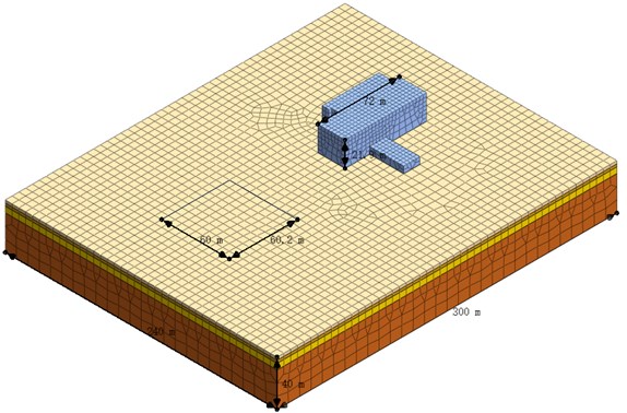
Table 3Physical and mechanical parameters of different strata
Items | Density / (kg/m3) | Elastic modulus / (MPa) | Friction angle / (°) | Cohesion / (kPa) | Poisson ratio |
Overlying soil | 1750 | 340 | 21 | 19.5 | 0.32 |
Strongly weathered rock | 2040 | 26500 | 35 | 780 | 0.26 |
Moderately weathered rock | 2300 | 33910 | 42 | 1500 | 0.22 |
Slightly weathered rock | 2700 | 37000 | 56 | 2200 | 0.20 |
In order to study the damping effects of the depth and width of the damping ditch and the horizontal distance between the damping ditch and the explosion source, different damping ditch schemes are set and compared with the schemes without damping ditch, and the damping effect of the damping ditch is analyzed. The impact of blasting vibration on the factory building is analyzed by extracting the vibration velocities at different distances between the factory building and the blasting zone. The relevant parameters of different damping ditch schemes are shown in Table 4. The calculation formula of damping ratio is introduced to quantitatively analyze the damping effect of damping ditch, which can be expressed as:
where represents the vibration velocity without damping ditch; represents the vibration velocity with damping ditch; represents the damping ratio of damping ditch.
Fig. 8Attenuation curve of blasting seismic wave
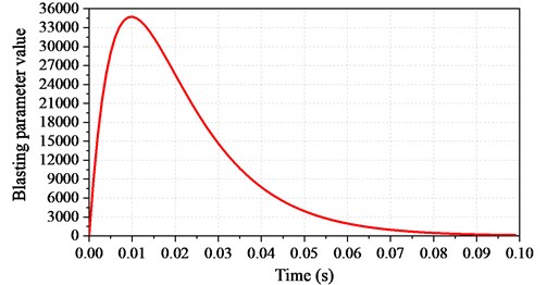
Table 4Setting scheme of damping ditch
Scheme | Depth / (m) | Width / (m) | Distance / (m) |
1 | 1 | 1 | 4 |
2 | 1.5 | 1 | 4 |
3 | 2 | 1 | 4 |
4 | 1 | 2 | 4 |
5 | 1 | 3 | 4 |
6 | 1 | 1 | 8 |
7 | 1 | 1 | 12 |
Table 5Comparison results of blasting vibration velocity
Measuring point | Blasting center distance / m | Calculated value / (cm/s) | Regression value / (cm/s) | Relative error / % |
1 | 5 | 173.96 | 161.87 | 7.47 |
2 | 7 | 60.73 | 55.53 | 9.36 |
3 | 12 | 10.92 | 9.87 | 10.64 |
In order to verify the correctness of the created numerical analysis model, the vibration velocity calculated by numerical simulation is compared with the results obtained from the vibration velocity attenuation formula of field monitoring. It can be seen from Table 5 that the numerical simulation calculation value is close to the regression value of on-site monitoring, and the relative error is 7.47 %-10.64 %. With the increase of blasting center distance, the relative error increases gradually.
4.2. Influence of damping ditch depth
In order to analyze the influence of damping ditch depth on the damping effect, Scheme 1, Scheme 2, and Scheme 3 are regarded as a group and compared with the case without a damping ditch. The damping ditch width and the horizontal distance between the damping ditch and the blasting source in three schemes are kept consistent, and the damping ditch depths are 0.8 m, 1.0 m and 1.2 m, respectively. The comparative analysis results of calculated vibration velocity are shown in Fig. 9. The damping ratio of the damping ditch with different depths is shown in Fig. 10. It can be seen from Fig. 9 the vibration velocity decreases with the increase of the distance from the measuring point to the blasting zone in case of damping ditches with different depths. When the distance from the measuring point to the blasting zone is not more than 30 m, the vibration velocity decreases rapidly. When the distance is greater than 30 m, the vibration velocity decreases slowly.
Fig. 9Variation of vibration velocity with horizontal distance from measuring point to blasting zone
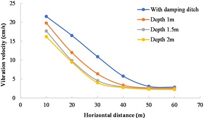
Fig. 10Variation of damping ratio with horizontal distance from measuring point to blasting zone
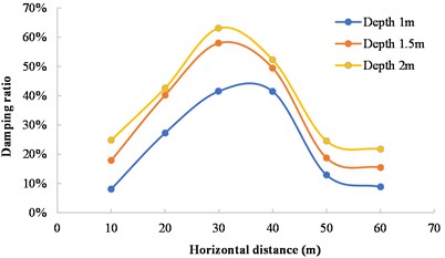
It can be seen from Fig. 10 that with the increase of the distance from the measuring point to the blasting zone, the damping ratio first increases and then decreases. When the distance is 30 m, the damping ratio of three schemes reaches its maximum. The vibration reduction effect is the most obvious when the excavation depth is 1.2 m, and the damping ratio reaches 63.09 %. The damping ratio at an excavation depth of 1.5 m is 58 % and that at an excavation depth of 1.0 m is 41.56 %. When the excavation width of the damping ditch and the distance from the measuring point to the blasting zone remains unchanged, the damping effect becomes obvious as the excavation depth of the damping ditch increases within a certain range.
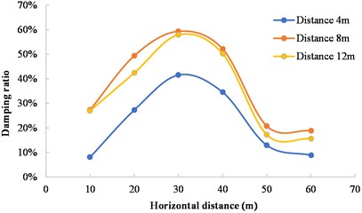
4.3. Influence of damping ditch distance
In order to analyze the influence of the horizontal distance between the damping ditch and the blasting source on the damping effect, Scheme 1, Scheme 6, and Scheme 7 are regarded as a group and compared with the case without damping ditch. The damping ditch depth and width in three schemes are kept consistent, and the horizontal distances between the damping ditch and the blasting source are 4 m, 8 m and 12 m, respectively. The comparative analysis results of calculated vibration velocity are shown in Fig. 11. The damping ratio of damping ditch with different distances is shown in Fig. 12. The vibration velocity continues to decay as the distance from the measuring point to the blasting zone increases when damping ditches are used with different distances. The damping ratio of the damping ditch with different distances reaches its maximum when the horizontal distance of the measuring point is 30 m. The maximum damping ratio is 41.56 % when the horizontal distance between the damping ditch and the blasting source is 4 m. The maximum damping ratio is 59.33 % when the horizontal distance is 8 m, and the maximum damping ratio is 57.93 % when the horizontal distance is 12 m. This shows that Scheme 7 (the distance between the damping ditch and the blasting source is 12 m) has the best damping effect. The reason for this phenomenon is that when the damping ditch is arranged far away, the vibration velocity has been mostly attenuated, so the damping effect of the damping ditch has not been fully utilized.
Fig. 11Variation of vibration velocity with horizontal distance from measuring point to blasting source
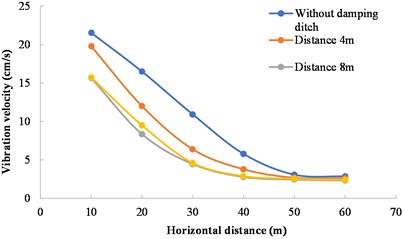
Fig. 12Variation of damping ratio with horizontal distance from measuring point to blasting source
4.4. Influence of damping ditch width
In order to analyze the influence of damping ditch width on the damping effect, Scheme 1, Scheme 4, and Scheme 5 are regarded as a group and compared with the case without damping ditch. The damping ditch depth and the horizontal distance between the damping ditch and the blasting source in three schemes are kept consistent, and the damping ditch widths are 1 m, 2 m and 3 m, respectively. The comparative analysis results of calculated vibration velocity are shown in Fig. 13. The damping ratio of damping ditch with different widths is shown in Fig. 14. In Fig. 13, the vibration velocity in three schemes of damping ditch presents the same decreasing trend. When the distance between the measuring point and the blasting zone is more than or equal to 30 m, the vibration velocity difference is very small for the damping ditches with different widths. It can be seen from Fig. 14 that the damping ratio in three schemes of damping ditch also presents the same change trend. The maximum damping ratio is 41.56 % when the damping ditch width is 1 m, and the maximum damping ratio is 42.84 % when the damping ditch width is 2 m. The maximum damping ratio is 44.65 % when the damping ditch width is 3 m, which has the best damping effect. When the excavation depth of the damping ditch and the horizontal distance between the damping ditch and the blasting zone remain unchanged, the larger the excavation width of the damping ditch is, the more obvious the damping effect of the damping ditch is. However, compared with the damping ditch depth and the distance between the damping ditch and the blasting zone, the damping effect of the excavation width of the damping ditch is much smaller.
Fig. 13Variation of vibration velocity with distance between measuring point and blasting zone
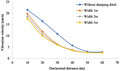
Fig. 14Variation of damping ratio with distance between measuring point and blasting zone
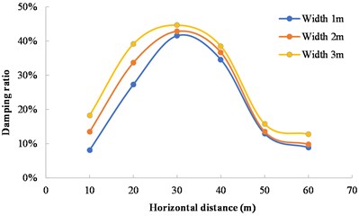
Fig. 15Contours of velocity field
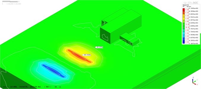
a) Without damping ditch
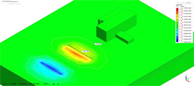
b) With damping ditch
The variation of velocity field shows the same trend under different damping ditch parameters. Therefore, the working condition of damping ditch distance of 8 m (Scheme 6) is taken as an ideal case for analysis. The contours of the maximum velocity field with or without damping ditch are shown in Fig. 15. One side of the factory building near the blasting zone is mainly affected by the reflected pressure of explosion, which is the key area of blasting vibration absorption. In the numerical model without damping ditch (Fig. 15(a)), there are velocity contours around the factory building, but in the numerical model with damping ditch (Fig. 15(b)), the maximum range of velocity contour did not reach the factory building, indicating that the existence of damping ditch significantly shortens the propagation distance of blasting seismic wave. At the side close to the factory building, the influence range of blasting seismic wave is large when there is no damping ditch. When the damping ditch is set, the damping ditch blocks the propagation of blasting seismic waves. The vibration speed at the side of the damping ditch is significantly reduced, which can intuitively illustrate the function of damping ditch.
5. Discussion
In the process of blasting, the particle vibration velocity is mainly caused by the blasting surface wave. The surface wave decays rapidly in the vertical direction, and the influence depth is only about one wavelength depth. The energy of blasting seismic wave is concentrated near the interface and only propagates along the surface, and the energy of wave attenuates along the propagation direction. According to the propagation characteristics of surface wave, it will propagate along the surface of the damping ditch after it propagates to the damping ditch. Reflection and diffraction will occur at both sides of the damping ditch, as shown in Fig. 16. The propagation path with damping ditch is changed compared with that without damping ditch. If no damping ditch is provided, the propagation distance of the surface wave from the explosion source to the measuring point is . When a damping ditch is provided, the propagation distance of the surface wave becomes (where is the depth of the damping ditch). The damping trench increases the propagation distance of surface waves. Combining with Sadowski's formula (Eq. (1)), the calculation formula (Eq. (9)) of the vibration velocity with the damping ditch can be derived:
where represents the particle vibration velocity in case of using a damping ditch (cm/s); represents the depth of the damping ditch (m).
Comparing the vibration speed of the surface particles in case of using a damping ditch and in that without a damping ditch provided, that is, Equation (10) can be obtained by combining Eq. (1) and E q. (9):
According to the propagation law of surface wave and Eq. (10), under the same blasting environment, the vibration velocity of surface particles caused by blasting vibration hardly depends on the excavation width of damping ditch. It mainly depends on the excavation depth and blasting center distance of damping ditch.
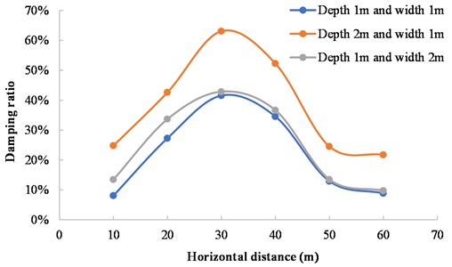
The damping ditch both affects the propagation of surface wave, and the propagation of body wave. The blasting charge is in the form of a cylindrical charge, and the effective stress field is approximately ellipsoid-shaped. The body wave in the far region of the explosion source can be regarded as a cylindrical wave. When the body wave propagates to the damping ditch, due to the change of the propagation cross section, even if the material and wave impedance of the propagation medium are the same, reflection and transmission will occur at the sudden change of the cross section, as shown in Fig. 16. The damping rates under different depths and widths of the damping ditch are shown in Fig. 17. The damping rate of the damping ditch with the depth of 2 m and width of 1 m is significantly higher than that of the damping ditch with the depth of 1 m and width of 2 m. Therefore, the depth of the damping ditch has an obvious attenuation effect on the body wave, while the width of the damping ditch has little impact on the damping effect. The weakening effect of the damping ditch on body wave is related to the energy of blasting seismic wave. The greater the energy of wave is, the faster the attenuation is. The weakening mechanism of the damping ditch to the body wave is to concentrate the energy of the body wave first, and then is to promote its attenuation within the scope of the damping ditch.
The research results of this paper are consistent with the existing research results on the vibration isolation performance of the damping ditch [22-24]. Various experimental results, theoretical analysis results and numerical simulation results show that the vibration isolation effect of the damping ditch mainly depends on the depth of the barrier. The deeper the damping ditch is, the better the vibration isolation effect is. Generally, the barrier depth is required to be greater than twice the Rayleigh wavelength. However, due to the factors such as land space limitation, construction difficulty and project cost, it is impossible to set a deep damping ditch. The damping ditch can only be used for vibration isolation problems with medium and high frequency vibration, and it has almost no vibration isolation effect for low frequency vibration [25]. Some studies [26] show that for medium and low frequency vibration waves, the more effective vibration isolation method is to use wave impedance plate as a vibration isolation barrier. In the following research, the combined structure of vibration isolation trench and wave impedance plate will be studied.
Fig. 16Propagation process of blasting seismic wave
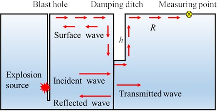
Fig. 17Variation of damping ratio of damping ditch with different depths and widths
6. Conclusions
A large number of field monitoring tests with or without damping ditch were carried out based on the foundation pit excavation project. The propagation characteristics and the attenuation laws of blasting seismic waves were studied, and the damping effect of damping ditch on blasting seismic wave was also investigated. The MIDAS GTS/NX software was used to create numerical models of damping ditches with different geometric parameters, and the laws of vibration velocity and damping ratio with the distance of measuring points were analyzed. The main conclusions are summarized as follows:
1) Based on the Sadovsky’s empirical formula, an optimized blasting vibration velocity attenuation model was created by using the waveform subsection correspondence method. By comparing the monitoring data and calculation results, the average errors in the radial and vertical directions are 17.04 % and 10.76 % respectively. The created attenuation model can predict the vibration velocity more accurately.
2) Based on the regression analysis of the field monitoring data, the blasting vibration velocity attenuation model with damping ditch was obtained. Compared with the conventional blasting without damping ditch, it is found that the damping ditch can significantly reduce the blasting seismic effect. After exceeding the reasonable setting distance of the damping ditch, the damping effect of the damping ditch decreases rapidly with the increase of the distance between the damping ditch and the explosive source. Within the reasonable setting distance of the damping ditch, the damping effect is significant in the area near the explosion source.
3) The damping ratios of the damping ditches with different geometric parameters demonstrate the same variation law. The damping ratio first increases and then decreases with the increase of the distance between the measuring points. In the range of parameters of damping ditch, the damping ratio of damping ditch increases with the increase of excavation depth, and the maximum damping ratio is 63.09 %. The damping ratio of damping ditch also increases with the increase of excavation width, and the maximum damping rate is 44.65 %. However, under three different ditch distances of 4 m, 8 m and 12 m, the damping ratio reaches its maximum when the distance is 8 m, and the damping ratio is 59.33 %.
4) The influence degree of the damping ditch geometry on the blasting damping ratio, from large to small, depends on the excavation depth of the damping ditch, the horizontal distance between the damping ditch and the explosive source, and the excavation width of the damping ditch. The attenuation of the surface wave is only related to the damping ditch depth, and the damping ditch width has no effect on the surface wave.
References
-
K. Wang, Z. Liu, X. Qian, and Y. He, “Dynamic characteristics and damage recognition of blast-induced ground vibration for natural gas transmission pipeline and its integrated systems,” Mechanical Systems and Signal Processing, Vol. 136, p. 106472, Feb. 2020, https://doi.org/10.1016/j.ymssp.2019.106472
-
J. Niu, X. Jiang, F. Wang, and H. Yang, “Comparative analysis of dynamic responses of different rock tunnel slopes,” Geotechnical and Geological Engineering, Vol. 38, No. 2, pp. 1409–1430, Apr. 2020, https://doi.org/10.1007/s10706-019-01099-2
-
J.-J. Zhang, J.-Y. Niu, X. Fu, L.-C. Cao, and Q. Xie, “Shaking table test of seismic responses of anchor cable and lattice beam reinforced slope,” Journal of Mountain Science, Vol. 17, No. 5, pp. 1251–1268, May 2020, https://doi.org/10.1007/s11629-019-5712-4
-
Z. Li, J. Li, and H. Li, “Effect of concave terrain on explosion-induced ground motion,” International Journal of Rock Mechanics and Mining Sciences, Vol. 148, p. 104948, Dec. 2021, https://doi.org/10.1016/j.ijrmms.2021.104948
-
C. Pan, X. Li, J. Li, and J. Zhao, “Numerical investigation of blast-induced fractures in granite: insights from a hybrid LS-DYNA and UDEC grain-based discrete element method,” Geomechanics and Geophysics for Geo-Energy and Geo-Resources, Vol. 7, No. 2, May 2021, https://doi.org/10.1007/s40948-021-00253-6
-
Z. Song, K. Man, and X. Liu, “Blasting vibration monitoring scheme and its application,” Journal of Vibroengineering, Vol. 23, No. 7, pp. 1640–1651, Nov. 2021, https://doi.org/10.21595/jve.2021.22058
-
X. Wang, J. Li, X. Zhao, and Y. Liang, “Propagation characteristics and prediction of blast-induced vibration on closely spaced rock tunnels,” Tunnelling and Underground Space Technology, Vol. 123, p. 104416, May 2022, https://doi.org/10.1016/j.tust.2022.104416
-
S. Xiao, H. Wang, and G. Dong, “A preliminary study on the design method for large-diameter deep-hole presplit blasting and its vibration-isolation effect,” Shock and Vibration, Vol. 2019, pp. 1–11, Nov. 2019, https://doi.org/10.1155/2019/2038578
-
D.-P. N. Kontoni and A. A. Farghaly, “Mitigation of train-induced vibrations on nearby high-rise buildings by open or geofoam-filled trenches,” Journal of Vibroengineering, Vol. 22, No. 2, pp. 416–426, Mar. 2020, https://doi.org/10.21595/jve.2019.20523
-
P. Jayawardana, D. P. Thambiratnam, N. Perera, and T. Chan, “Dual in-filled trenches for vibration mitigation and their predictions using artificial neural network,” Soil Dynamics and Earthquake Engineering, Vol. 122, pp. 107–115, Jul. 2019, https://doi.org/10.1016/j.soildyn.2019.04.006
-
Q. Bo, L. Ali, and D.-M. Irini, “Numerical study of wave barrier and its optimization design,” Finite Elements in Analysis and Design, Vol. 84, pp. 1–13, Jul. 2014, https://doi.org/10.1016/j.finel.2014.02.002
-
A. Alzawi and M. Hesham El Naggar, “Full scale experimental study on vibration scattering using open and in-filled (GeoFoam) wave barriers,” Soil Dynamics and Earthquake Engineering, Vol. 31, No. 3, pp. 306–317, Mar. 2011, https://doi.org/10.1016/j.soildyn.2010.08.010
-
T. Bose, D. Choudhury, J. Sprengel, and M. Ziegler, “Efficiency of open and infill trenches in mitigating ground-borne vibrations,” Journal of Geotechnical and Geoenvironmental Engineering, Vol. 144, No. 8, p. 04018048, Aug. 2018, https://doi.org/10.1061/(asce)gt.1943-5606.0001915
-
X. Tian, Z. Song, and J. Wang, “Study on the propagation law of tunnel blasting vibration in stratum and blasting vibration reduction technology,” Soil Dynamics and Earthquake Engineering, Vol. 126, p. 105813, Nov. 2019, https://doi.org/10.1016/j.soildyn.2019.105813
-
X. Liu, Y. Zeng, H. Li, X. Xia, J. Li, and Z. Li, “Research on blasting vibration effect and time-frequency characteristics of vibration signals in a road corridor at Xianning nuclear power station,” Journal of Vibroengineering, Vol. 23, No. 4, pp. 823–846, May 2021, https://doi.org/10.21595/jve.2021.21848
-
B. Duan, S. Shen, G. Ta, K. Sun, W. Hou, and L. Gu, “Effect of the size and position of a damping ditch on the reduction of the blasting vibration,” Advances in Civil Engineering, Vol. 2020, pp. 1–15, Aug. 2020, https://doi.org/10.1155/2020/8855742
-
Y. Gou, X. Shi, J. Zhou, X. Qiu, X. Chen, and X. Huo, “Attenuation assessment of blast-induced vibrations derived from an underground mine,” International Journal of Rock Mechanics and Mining Sciences, Vol. 127, p. 104220, Mar. 2020, https://doi.org/10.1016/j.ijrmms.2020.104220
-
C. González-Nicieza, M. I. Álvarez-Fernandez, A. E. Alvarez-Vigil, D. Arias-Prieto, F. López-Gayarre, and F. L. Ramos-Lopez, “Influence of depth and geological structure on the transmission of blast vibrations,” Bulletin of Engineering Geology and the Environment, Vol. 73, No. 4, pp. 1211–1223, Nov. 2014, https://doi.org/10.1007/s10064-014-0595-7
-
I.-T. Wang, T.-C. Wang, and C.-Y. Lee, “Analysis of blasting vibration wave propagation based on finite element numerical calculation and experimental investigations,” Journal of Vibroengineering, Vol. 19, No. 4, pp. 2703–2712, Jun. 2017, https://doi.org/10.21595/jve.2017.17404
-
S. Murmu, P. Maheshwari, and H. K. Verma, “Empirical and probabilistic analysis of blast-induced ground vibrations,” International Journal of Rock Mechanics and Mining Sciences, Vol. 103, pp. 267–274, Mar. 2018, https://doi.org/10.1016/j.ijrmms.2018.01.038
-
Z.-X. Zhang, L.-Y. Chi, and C. Yi, “An empirical approach for predicting burden velocities in rock blasting,” Journal of Rock Mechanics and Geotechnical Engineering, Vol. 13, No. 4, pp. 767–773, Aug. 2021, https://doi.org/10.1016/j.jrmge.2021.04.004
-
G. L. Sivakumar Babu, A. Srivastava, K. S. Nanjunda Rao, and S. Venkatesha, “Analysis and design of vibration isolation system using open trenches,” International Journal of Geomechanics, Vol. 11, No. 5, pp. 364–369, Oct. 2011, https://doi.org/10.1061/(asce)gm.1943-5622.0000103
-
P. H. Tsai, “Effects of open trench dimension on screening effectiveness for high speed train induced vibration,” Applied Mechanics and Materials, Vol. 256-259, pp. 1187–1190, Dec. 2012, https://doi.org/10.4028/www.scientific.net/amm.256-259.1187
-
C.-H. Chiang and P.-H. Tsai, “A numerical study of the screening effectiveness of open trenches for high-speed train-induced vibration,” Shock and Vibration, Vol. 2014, pp. 1–11, 2014, https://doi.org/10.1155/2014/489090
-
F. X. Zhou, Q. Ma, and Z. X. Zhou, “2D analysis of vibration-isolation efficiency of an open trench-wave impedence block barrier,” (in Chinese), Rock and Soil Mechanics, Vol. 41, No. 12, pp. 4087–4092, 2020, https://doi.org/10.16285/j.rsm.2020.0484
-
N. Chouw, R. Le, and G. Schmid, “An approach to reduce foundation vibrations and soil waves using dynamic transmitting behavior of a soil layer,” Bauingenieur, Vol. 66, pp. 215–221, 1991.
About this article

This work is supported by the National Key R & D Program of China (No. 2017YFC0504901).
