Abstract
In this paper, a complete finite element model of disc brake considering the ventilated brake disc, pads, back-plate, caliper, bracket, piston, rubber bushes and simplified fluid model driving piston is established. The pressure and speed dependent friction model and temperature field are considered. The results of complex eigenvalue analysis (CEA) show consistence with the existing achievements, thus the feasibility of the established model is verified. Subsequently, the transient dynamic analysis of the brake system is carried out for different exerting process of the pressure which represents the operation of different drivers. Besides, the vibration responses of different brake pressure and different speed are also investigated. The evolution process of the stability is studied by time-frequency analysis (STFT method). Both CEA and time-frequency analysis show the squeal tends to appear in the case of high friction coefficient, low speed and low brake pressure. It can also be found that the vibration frequency and its energy are not constant but fluctuate in a certain range. The results of different pressure exerting processes with simplified fluid model driving piston show that vibration response of disc brake not only depends on the value of brake pressure but also depends on the pressure exerting process. It is supposed that brake pressure and rotational speed determine the frequency of squeal while the process of exerting pressure determines the existing duration of brake squeal.
1. Introduction
Brake squeal has always been an important concern of quality problems in the automotive industry. Brake manufacturers spend up to 50 % of their R&D budget on vibration, the disturbing brake noise costs more than half of the after-sale service expenses [1]. Among all the noises generated by brakes, squeal is the most common and disturbing one for both passengers and the environment [2]. Many efforts are made to understand and reduce this phenomenon. Although there being no precise definition, it is generally accepted that squeal is a high-frequency noise (higher than 1000 Hz) generated by the vibration of the disc [3]. Chikaromic [4] recognized that brake squeal was due to self-excited vibration generated by a frictional pair with a static coefficient of friction higher than the dynamic coefficient or a friction coefficient decreasing with the speed, this was so-called stick-slip phenomenon. In both cases, the varying friction forces on the pad-disc interface were supposed to be the cause of squeal. Spurr [5] thought the sprag-slip phenomenon caused by geometric constraints from configuration viewpoint and kinematic constraints in terms of motions and forces was the main reason of brake squeal. Although Chen [6] proposed that the modal coupling between the in-plane and out-of-plane modes could be responsible for high frequency squeal, Yang [7] and Papinniemi [8] stated that squeal noises were only caused by the in-plane vibration of the disc. Liu and Wang’s researches [9, 10] showed that brake vibration and squeal had obvious nonlinear properties. Actually, since the brake squeal involves the tribology, nonlinear dynamics, material science, etc., there is no common theory or method to perfectly explain brake squeal up to now. Almost for any mechanism, a counterexample can be found.
Nagy, Cheng and Hu [11] firstly conducted nonlinear transient dynamic analysis by using finite element method. They investigated the effect of nonlinear friction coefficient between the brake disc and pad on the stability of brake system. At present, the finite element method (FEM) is very popular in studying brake squeal since this method may depict the real structure and is faster and less expensive than the experimental method. In addition, it also allows predicting the brake instability at the stage of design. Two different FEM methods are commonly used to study the brake squeal: the complex eigenvalue analysis (CEA) and transient dynamic analysis [12]. Liu [13], Nouby [14] and Trichês [15] used CEA method to study the stability of disc brake. This method is very time-efficient and may predict the unstable frequencies but it’s difficult to be used to investigate the transient nonlinear response in time domain. Brake squeal is a typical nonlinear transient event due to the strong nonlinearities in a brake system associated with the contact problems, disc rotation, material nonlinearity, etc. The transient dynamic analysis can be used to predict true unstable frequencies (those found in experiments) in principle, but it is very time consuming and requires lots of computational resources [12]. Sinou [16] and Oberst [17] used transient dynamic analysis to study the time domain response of a disc-pad system, Ouyang [18] studied disc brake squeal by transient analysis combined with heat analysis. Esgandari [19] proposed an Implicit-explicit co-simulation of brake noise and the simulation results are correlated with the vehicle test results. Fazio [20] investigated the reduction strategy for a brake system and this strategy allows to predict correctly both the non-linear static equilibrium and the stability analysis at this equilibrium. However, almost all these literatures assumed that the friction coefficient was constant and most researchers didn’t consider the effect of brake fluid in brake cylinder for simplicity of research. Besides, although different drivers can produce the different brake pressure and brake process and these may result in the different results about brake squeal propensity, few literatures consider these factors and perform the corresponding research. The research on these problems is very helpful to reveal the mechanism of the brake squeal.
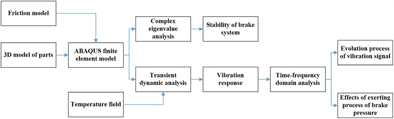
Aiming at the above problems, this paper establishes a complete model of disc brake containing the ventilated brake disc, pads, back-plate, caliper, bracket, piston, brake fluid and rubber bushes. In this model, the temperature field and the friction model which depends on brake pressure and rotational speed is considered. Next, by using complex modal analysis, the coefficient of friction, brake pressure, rotational speed of disc act as the control parameters to investigate the impacts on brake system’s stability. The results of CEA show the consistence with the existing achievements, thus the feasibility of the established model is verified. Then, the transient dynamic analysis of disc brake system is carried out to research the different exerting process of the brake pressure which represents the operation of different drivers. The vibration responses of different brake pressure and different speed are also investigated. Finally, the evolution process in time-frequency domain of the vibration responses of different pressure exerting processes with simplified fluid model driving piston and pressure and speed dependent friction model are obtained by using the time-frequency analysis (STFT method). The flow chart of this paper is shown below:
Fig. 1Flow chart
2. Complete finite element model of the disc brake
The floating-caliper disc brake is most popular in automobile industry now. The model of this kind of brake is shown in Fig. 2(a).
Fig. 2a) Three-dimensional model and b) finite element model of disc brake
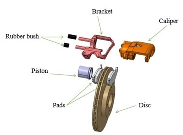
a)
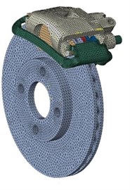
b)
2.1. Complete structures
Many researchers [13, 15, 17] have considered a simplified FE model of disc brake assembly including a disc and two pads. Few built the FE model with complete parts. This paper builds a disc brake FE model containing a brake disc, two pads, a brake caliper, a bracket, a piston, brake fluid and two rubber bushes. The materials of these parts are shown in Table 1 respectively. The finite element model of brake assembly is shown in Fig. 2(b).
Table 1Materials of different parts
Part | Material | Density (kg/m3) | Young’s modulus (GPa) | Poisson ratio (–) |
Disc, Caliper, Bracket | Cast iron | 7000 | 92.2 | 0.25 |
Piston, Back-plate | Steel | 7800 | 209 | 0.28 |
Pad | Composite | 1550 | 2.2 | 0.25 |
Rubber bush | Rubber | 950 | 0.02 | 0.45 |
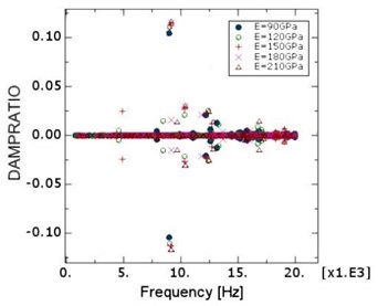
By using CEA method, some scholars have studied the effect of Young’s moduli of the pad and disc on brake squeal [13-15]. Besides, in our previous work, we have built a simplified brake system finite element model and studied the influence of Young’s moduli of brake disc. The results are shown in Fig. 3.
Fig. 3a) Simplified model of brake system and b) the effects of different Young’s moduli of disc on damping ratio
a)
b)
It can be concluded that the Young’s moduli of the pad and disc has an obvious effect on stability. Therefore, in this paper the change of Young’s moduli with temperature during transient dynamic analysis is considered. Since the material of brake pad is composite and anisotropic, the influence of the material property of pad on brake squeal is complex. The material of pad is assumed to be isotropic and also changes with the temperature.
2.2. Temperature fields of disc and pads
During braking the brake system converts the mechanical energy of vehicle into heat, thus the temperature on the contact faces of disc and pads increases. Ouyang [18] found a noticeable difference between the dynamic responses obtained with the thermal effect from those without the thermal effect. To create an accurate model, the temperature field of disc and pads is considered in transient dynamic analysis. According to Ref. [21, 22], the changes of the material properties of disc and pad are shown in Table 2.
Table 2Material properties of disc and pad
Temperature (°C) | 20 | 100 | 200 | 300 | |
Pad | Young's modulus (GPa) | 2.2 | 1.3 | 0.53 | 0.32 |
Conductivity ( / (m·K)) | 0.9 | 0.9 | 0.9 | 0.9 | |
Specific heat ( / (kg·K)) | 1200 | 1200 | 1200 | 1200 | |
Thermal dilatation (K-1) | 1×10⁻⁵ | 1×10⁻⁵ | 3×10⁻⁵ | 3×10⁻⁵ | |
Disc | Young's modulus (GPa) | 92.2 | 91 | 89 | 86 |
Conductivity ( / (m·K)) | 24 | 24 | 24 | 24 | |
Specific heat ( /(kg·K)) | 460 | 460 | 460 | 460 | |
Thermal dilatation (K-1) | 1.08×10⁻⁵ | 1.08×10⁻⁵ | 1.08×10⁻⁵ | 1.08×10⁻⁵ |
2.3. Simplified brake fluid model
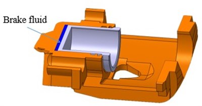
To consider the brake fluid’s capability of propagating vibrations, the fluid in cylinder is assumed to be a quasi-hydrostatic elastomer, as shown in Fig. 4. Since the matrix of brake fluid is usually made from alcohols and ethers whose density usually range from 900 to 1000 kg/m3. The elastomer’s density is 900 kg/m3 and its Young’s modulus which is the reciprocal of compression coefficient is 2000 MPa.
Fig. 4Cutaway view of the caliper and the piston
2.4. Pressure and speed dependent friction model
In authors’ knowledge, most of researchers treated the friction coefficient as a constant. But in reality, the friction coefficient changes with relative speed between the disc and pad, brake pressure and the temperature of brake pairs, etc. The change of friction coefficient is one of the main reasons of vibration’s nonlinear time-varying phenomenon. A pressure and speed dependent friction model for a specific brake pad and disc based on a great deal of experimental data is established, and the feasibility is verified. The friction experiments are carried out on the wear testing machine, as shown in Fig. 5.
Fig. 5Pin-disc friction and wear testing machine
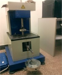
a) Experimental machine
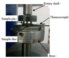
b) Friction pairs
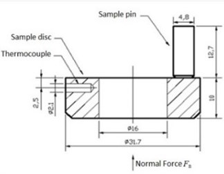
c) The structure and size of samples
According to Ref. [23-25], it is recognized that the dynamic friction model could be studied and set up from the energy point of view as follows:
The expression of the transient friction coefficient in the Eq. (1) can be simplified as:
Parameters of dynamic friction model are identified based on experimental data, the semi-empirical dynamic friction model based on the theoretical analysis and the experimental data can be summarized as follows:
where is 0.16-0.25; is 0.2-0.5; is 0.05; is 0.01-0.02; is 0.4-0.6; is 0.01-0.018. In this paper, let be 0.5, be 0.5 and be 0.05. If time tends to be infinity, the pressure and speed dependent friction model can be got:
where is the environment temperature, is the brake pressure, is the relative slip speed between the contact surfaces of disc and pad. This friction model is considered by setting contact property in ABAQUS. During both complex eigenvalue analysis and transient dynamic analysis, the friction coefficient changes with the change of rotation speed and brake pressure based on this friction model.
3. Complex eigenvalue analysis
The CEA method is very popular in the industry [13-15], thus here it is used to study the stability of disc brake for the complete model built in Section 2 and the effects of some key parameters, such as the friction coefficient of the contact surfaces, the brake pressure and the rotational speed of disc. The feasibility of the established model is also investigated.
3.1. Effects of friction coefficient
Brake squeal is believed to be caused mainly by friction-induced dynamic instability, so friction coefficients have an important effect on the stability of system. Here the friction coefficient that varies from 0.2 to 0.6 is studied for the case that , and the rotational speed of disc are 20 °C, 1 MPa and 10 rad/s respectively. According to Ref. [17], in ABAQUS, a vibration mode is considered to be unstable if the effective damping ratio is negative, and the effective damping ratio is expressed as:
where is the complex eigenvalue of established disc brake model.
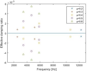
Through the complex frequency step in ABAQUS/Standard, the effective damping ratios for different friction coefficients are obtained and shown in Fig. 6.
Fig. 6Effective damping ratios for different friction coefficients
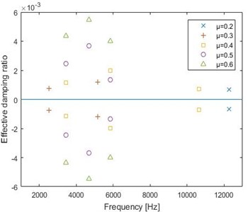
It can be found that for friction coefficient of 0.2, the unstable mode only exists at 12000 Hz and the absolute value of effective damping ratio is very little, therefore the propensity of brake squeal is very weak, and that the absolute value of effective damping ratio increases with an increase of the friction coefficient, which means large friction coefficients lead to the instability of brake system. This result has a good agreement with Ref. [13, 15].
3.2. Effects of brake pressure
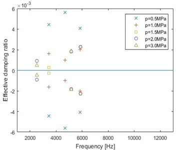
The model of friction coefficient depending on pressure and speed described in Section 2 is considered here. Assuming that is 20 °C, the rotational speed of disc is 10 rad/s and the friction radius is 0.1 m respectively, the effects of brake pressure are studied for the range of 0.5 MPa to 3 MPa which is normally used in FE models [13, 14]. The effective damping ratios for different brake pressures are shown in Fig. 7.
The simulation results show that when pressure is low, like 0.5 MPa, the absolute value of effective damping ratio is high, which means the system tends to be unstable. The variety of effective damping ratio is not clear when the brake pressure changes from 1 MPa to 3 MPa. These results are similar to the change rule of experiment results in Ref [26]. This is attributed to both effects of increasing brake pressure and the reduction of the friction coefficient with the increase of brake pressure. It’s obvious that taking into account of the relationship between brake pressure and friction coefficient is very necessary.
Fig. 7Effective damping ratios for different brake pressures
3.3. Effects of rotational speed of disc
The rotational speed of disc can also affect the friction coefficient between friction pair. The pressure and speed dependent friction coefficient is shown in Eq. (4). Assuming that , brake pressure and the friction radius are 20 °C, 1 MPa and 0.1 m respectively, the effects of rotational speed varying from 5 rad/s to 25 rad/s on the stability are investigated here since the squeal usually appears at low speed. The effective damping ratios for different rotational speeds are simulated and shown in Fig. 8.
Fig. 8Effective damping ratios for different rotational speeds
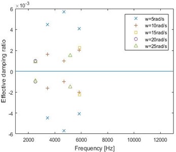
From Fig. 8, it is found that the negative effective damping ratios exist at low rotational speed, and their absolute values are higher. This can explain why the brake squeal usually appears at low speed [13, 15]. At high speed, the number of unstable mode (or the negative effective damping ratios) reduces significantly. When the rotational speed is 15 rad/s, the system is unstable only around 6000 Hz. When rotational speed is 20 rad/s, the unstable mode is only around 3200 Hz.
In this section, the results of complex eigenvalue analysis for the conditions of different friction coefficient, different brake pressure and different rotational speed show the consistence with the existing achievements and actual situations. The established model considering the ventilated brake disc, pads, back-plate, caliper, bracket, piston, rubber bushes, simplified fluid model and pressure and speed dependent friction model is more complete and accurate, thus the model may reflect the complete features of disc brake system including some time-varying and nonlinear features. Obviously, the established model is feasible to accurately simulate transient dynamic response of disc brake.
4. Transient dynamic response and the analysis of evolution process by time-frequency method
4.1. Transient dynamic response of a disc brake system
The CEA method assumes that the model is a linear system, but for a real brake system, there are some nonlinear factors such as time-varying friction coefficient, material nonlinearity and contact property. Obviously, CEA method is difficult to describe the complete features of the system. But the transient dynamic analysis is able to introduce these nonlinear factors. Therefore, the transient dynamic analysis is conducted by using ABAQUS/Explicit and the transient dynamic responses of some nodes are studied.
The brake vibration is believed to be caused mainly by friction-induced dynamic instability, so research on the vibration of disc-pad contact surfaces is highlighted. 8 nodes on disc and pad contact faces are picked to reflect the vibration of disc and pad, as shown in Fig. 9. Through FEM considering the contacts of disc-pad, pad-bracket, pad-caliper, piston-pad, piston-cylinder, etc. and the relative sliding between disc and pads, the displacements of these nodes in normal direction are shown in Fig. 10.
Fig. 9Chosen nodes reflecting transient response
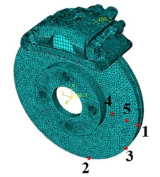
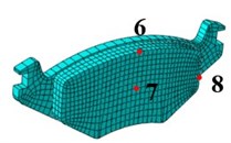
Fig. 10a) Vibration signals of disc and b) pad in normal direction
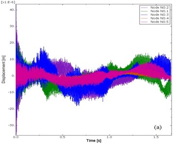
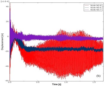
Fig. 10 shows that the vibration of node 1, 2, 3 on disc are very similar. For the vibration of the disc in radial direction, the node closer to the edge of disc has a more intensive vibration. For the pad, the node on the left and right edge of pad (like node No. 8) has a more intensive vibration. With transient dynamic analysis, in next section, this paper investigates the vibration response for different brake pressure, different rotational speed of disc and different duration of exerting brake pressure, and the time-frequency domain analysis is also conducted in MATLAB to study the evolution process of nodes’ vibration signals on disc brake model.
4.2. Evolution process analysis of vibration responses of disc brake
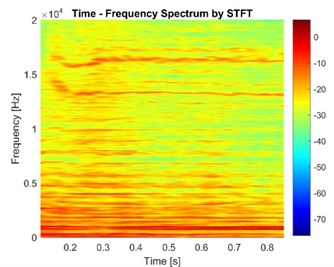
Here the short-time Fourier transform (STFT) is chosen to analyze the time-frequency spectrums of vibration responses since it can provide a suitable resolution at high frequency, high computational efficiency and operation simplicity. The short-time Fourier transform generates a time-frequency representation of a time domain signal by dividing up the signal into small time segments and performing Fourier transforms on each segment of time to derive the spectra. The short time-frequency Fourier transform of a signal can be expressed by:
where, is a constant length window. The is essentially the Fourier Transform of , a complex function representing the phase and magnitude of the signal over time and frequency in Hz. The function Spectrogram is used in MATLAB to obtain the time-frequency spectrum. The color scale of all the time-frequency spectra is the amplitude of Fourier transform of signal in dB, which represents the intensity of vibration.
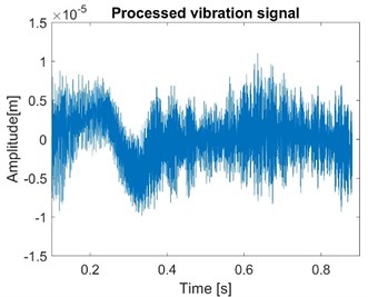
As an example, the node 1 is picked because other nodes have similar results. During braking processes, the rotational speed is constant and the brake pressure is constant after reaching the maximum value. Normal vibration signals of node 1 are obtained and show in Fig. 11.
Fig. 11Normal vibration signals of node 1 with both fluid model and friction model
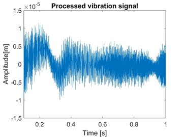
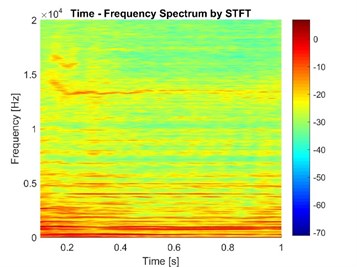
Fig. 11 shows the case considering the fluid model and friction model. As a comparison, the vibration signal of node 1 without the consideration of fluid model is simulated as shown in Fig. 12.
Fig. 12Normal vibration signals of node 1 in the model without fluid model
Comparing Fig. 11 and Fig. 12, it can be found that the vibration of the model considering the brake fluid is more violent. The reason is that the stiffness of the brake system reduces when the elasticity of fluid is considered. The STFT results also show that the frequency components of vibration with fluid model have higher energy and some new frequency components appear from 2 kHz to 10 kHz. Thus, the effect of the brake liquid should not be ignored when simulating the transient dynamic response of the brake system.
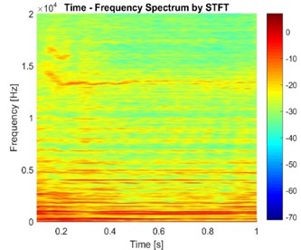
The vibration signal of node 1 with constant friction coefficient is simulated as shown in Fig. 13.
Fig. 13Normal vibration signals of node 1 with constant friction coefficient
Compared to Fig. 11, some frequency components in Fig. 13 are more continuous and last longer. The reason is that some time-varying characteristics of brake system are ignored since friction coefficient is regarded as a constant. To make brake model more accurate, it is necessary for the pressure and speed dependent friction model to be introduced in simulation.
The comparison between CEA method and transient dynamic analysis is shown in Fig. 14. During complex eigenvalue analysis, it is necessary to assume the parameters of brake system to be constant. However, some parameters may be variable with time in transient dynamic analysis, thus the instability frequencies analyzed by CEA method are not exactly consistent with that analyzed by transient dynamic method.
Fig. 14The comparison between CEA method and transient dynamic analysis
The results of two methods also show that most unstable frequencies are mainly in the range of 2000 Hz-6000 Hz. As for high frequency, both two methods show that the unstable frequency is around 12 kHz. This conclusion also indicates that the two methods are basically consistent.
Then, the time-frequency analysis of transient response of chosen node for different brake pressure, different rotational speed of disc and different duration of brake pressure exerting process is conducted as follows.
4.3. For different brake pressures
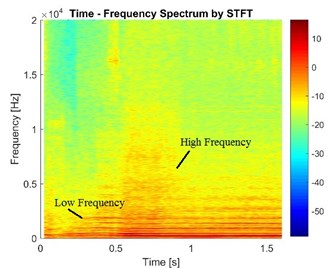
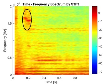
Without loss of generality, the rotational speed of disc and the duration of the pressure exerting process are set as 5 rad/s and 0.3 s respectively. With these definite parameters, the evolution process of transient responses for three brake pressures (0.5 MPa, 1.0 MPa, 1.5 MPa) are studied. Here node 1 on the disc is chosen since it can reflect the vibration of disc. The STFTs of vibration signals along normal direction of node 1 in different cases are shown in Fig. 15.
Fig. 15STFT of the vibration signals in the cases of different brake pressure
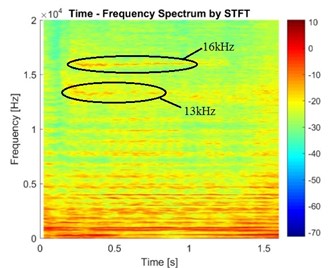
a) Case with brake pressure 0.5 MPa
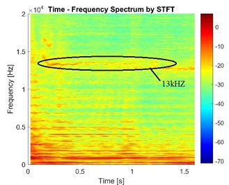
b) Case with brake pressure 1.0 MPa
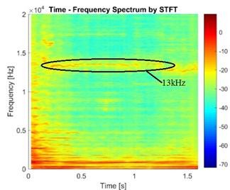
c) Case with brake pressure 1.5 MPa
It can be found from Fig. 15 that the brake pressure has an obvious effect on the stability of disc brake. In addition, some phenomena appear but cannot be seen in CEA: (1) The vibration frequency and its energy are not constant but fluctuate in a certain range in the process of braking. (2) Some frequency components with high energy only appear in a certain duration. (3) The frequency components are different at different times. When pressure is higher, the frequency component at 16 kHz disappears while the energy of frequency component at 13 kHz increases, and the energy of some other frequency components become smaller. Obviously, the pressure influences the frequency components in the vibration signal, but the rule of effects is not clear. This is very similar with the conclusions obtained in CEA.
4.4. For different rotational speeds of disc
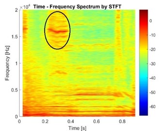
Assuming that the brake pressure is 1 MPa and the duration of process exerting pressure is 0.3 s, three cases of rotational speeds of disc (5 rad/s, 10 rad/s, 15 rad/s), are studied. Here the node 7 on pad is chosen because the node on disc has different duration contacting with pad when rotational speed is variable, which makes it difficult to compare the time-frequency responses in condition of different rotational speed. The STFTs of vibration signals along normal direction of node 7 in different speeds of disc are shown in Fig. 16.
Fig. 16The vibration signals in the case of different speeds
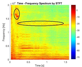
a) Case with speed 5 rad/s
b) Case with speed 10 rad/s
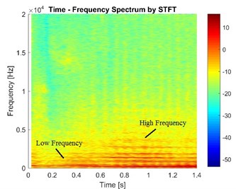
c) Case with speed 15 rad/s
The results show that higher frequency components weaken and gradually disappears when the rotational speed of the disc increases, which is in line with the results in CEA. Besides, the squeal is more likely to appear when the rotational speed is lower than 10 rad/s, which is approximatively 10.8 Km/h for a car. It can also be found that lower frequency components (below 2 kHz) appear ahead of higher frequency components and last for a longer time, so it is speculated that the higher frequency components are induced by the lower frequency components.
4.5. For different durations of exerting brake pressure
For same disc brake system and same velocity of vehicle, generally different properties of brake squeal appear for different drivers. The root cause is that different brake pressure exerting processes are applied. Thus, the vibration properties for different durations of exerting brake pressure are investigated here.
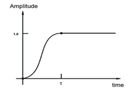
The amplitude of brake pressure called smooth step is expressed by Eq. (7), as shown in Fig. 17, since this kind of step is more like the operation of drivers for a brake system with the power assist device. The amplitude, , between two consecutive data points is:
where is the amplitude at , is the amplitude at ,and is:
The above function is such that at , at , and the first and second derivatives of are zero at and . This definition is intended to ramp up or down smoothly from one amplitude value to another which represents the operation of different drivers on brake.
Fig. 17The amplitude of pressure
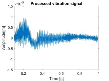
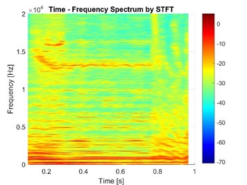
Assuming that the brake pressure is 1 MPa and the rotational speed of disc is 5 rad/s, three cases of the durations of process exerting pressure (0.1 s, 0.3 s and 0.5 s) are studied. To compare the time-frequency responses in condition of different processes exerting brake pressure, the node 7 on pad is chosen to make sure the chosen node has a complete process of exerting pressure. The STFTs of vibration signals along normal direction of node 7 in different cases are shown in Fig. 18.
Fig. 18The vibration signals in the case of different exerting time of pressure
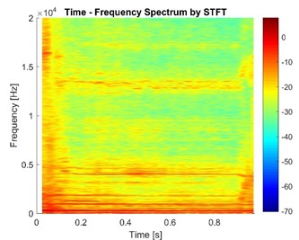
a) Case with duration of exerting pressure 0.1 s
b) Case with duration of exerting pressure 0.3 s
c) Case with duration of exerting pressure 0.5 s
The high frequency components ranging from 13 kHz to 16 kHz seem to be delayed and last for a longer time when the duration increases. This means that these frequency components depend on the pressure exerting process. It is supposed that when the pressure on the piston increases, the gradient of pressure on contact surfaces reaches a specific value and instability appears. This phenomenon shows that the vibration response of disc brake not only depends on the value of brake pressure but also depends on the exerting process of brake pressure.
Obviously, the influences of brake pressure, rotational speed and duration of exerting pressure are different. Both the value of pressure and the rotational speed of disc can influence the frequency components but in different ways. The duration of exerting brake pressure has an obvious effect on the start period when brake pressure still increases. However, after reaching maximum brake pressure, the time-frequency spectra are similar in the case of same brake pressure. It is supposed that brake pressure and rotational speed have close relationship with the frequency of squeal while the process of exerting pressure has close relationship with the duration of higher frequency components.
5. Conclusions
A complete finite element model of disc brake considering the ventilated brake disc, pads, back-plate, caliper, bracket, piston, rubber bushes and simplified fluid model is established. The pressure and speed dependent friction model and temperature filed are also considered. Through complex modal analysis, the effects of the coefficient of friction, brake pressure, rotational speed of disc on brake system’s stability are investigated. The results have a good agreement with the existing achievements and actual situations, which verifies the feasibility of the established model. Meanwhile, the normal vibration signals of specific nodes on brake disc and pads are obtained by using transient dynamic analysis. Finally, the STFT method is applied to investigate the stability evolution process and different processes of exerting brake pressure. The following conclusions can be gotten:
1) The simulation results by CEA show that high friction coefficient can lead to the instability of disc brake. Meanwhile, it is found that low speed also easily leads to the instability, which explains why squeal usually appears at low speed. When the brake pressure is low, the brake system is more likely to be unstable, but the rule of the effect of brake pressure is not clear. All these results show the good consistence with the existing achievements and actual situations, thus the established model is feasible.
2) The time-frequency domain analysis shows that the vibration frequency and its energy are not constant but fluctuate in a certain range in the process of braking. Some frequency components with high energy only appear in a certain duration and the frequency distribution is also different at different times.
3) Lower frequency components often appear ahead of higher frequency components and last for a longer time, it can be speculated that higher frequency components are induced by lower frequency components.
4) When the duration () of exerting brake pressure increases, higher frequency components appear and last until the brake pressure reaches the max value. This phenomenon shows that the vibration response of disc brake not only depends on the value of brake pressure but also depends on the process of exerting brake pressure.
5) Based on the results by time-frequency analysis, it is supposed that brake pressure and rotational speed have close relationship with the frequency of squeal, while the process of exerting pressure has close relationship with the duration of higher frequency components.
The central theme of this paper is to study the occurrence mechanisms of brake squeal. After that, we will obtain the deeper recognition about the brake squeal, and can choose the optimization targets more reasonably. In the future, we will focus on the optimization for brake system and find a way to attenuate unstable vibration and brake squeal.
References
-
Abendroth H., Wernitz B. The integrated test concept: dyno-vehicle, performance-noise. SAE Technical Paper, 2000, p. 2000-01-2774.
-
Kinkaid N. M., O’Reilly O. M., Papadopoulos P. Automotive disc brake squeal. Journal of Sound and Vibration, Vol. 267, Issue 1, 2003, p. 105-166.
-
Lang A. M., Smales H. An approach to the solution of disc brake vibration problems. Institute of Mechanical Engineering C, Vol. 37, 1983, p. 223-231.
-
Chikamori S. Study on brake noise. Journal of Japan Society of Automotive Engineer, Vol. 23, 1969, p. 125-130.
-
Spurr R. T. A theory of brake squeal. Proceedings of the Institution of Mechanical Engineers: Automobile Division, Vol. 15, Issue 1, 1961, p. 33-52.
-
Chen F., Quaglia R. L., Tan C. A. On automotive disc brake squeal Part I: Mechanisms and causes. SAE Technical Paper, 2003, p. 2003-01-0683.
-
Yang M., Afaneh A. H., Blaschke P. A study of disc brake high frequency squeals and disc in-plane/out-of-plane modes. SAE Technical Paper, 2003, p. 2003-01-1621.
-
Papinniemi A., Zhao J., Stanef D., et al. An investigation of in-plane vibration modes in disc brake squeal noise. SAE Technical Paper, 2005, p. 2005-01-3923.
-
Liu X., Zhao Y., Shan Y., et al. Nonlinear dynamics modeling and analysis of disc brake squeal considering acting process of brake force. Journal of Vibroengineering, Vol. 16, Issue 4, 2014, p. 1964-1976.
-
Wang H., Liu X., Shan Y., et al. Nonlinear behavior evolution and squeal analysis of disc brake based on different friction models. Journal of Vibroengineering, Vol. 16, Issue 5, 2014, p. 2593-2609.
-
Nagy L. I., Cheng J., Hu Y. K. A new method development to predict brake squeal occurrence. SAE Technical Paper, 1994, p. 942258.
-
AbuBakar A. R., Ouyang H. Complex eigenvalue analysis and dynamic transient analysis in predicting disc brake squeal. International Journal of Vehicle Noise and Vibration, Vol. 2, Issue 2, 2006, p. 143-155.
-
Liu P., Zheng H., Cai C., et al. Analysis of disc brake squeal using the complex eigenvalue method. Applied Acoustics, Vol. 68, Issue 6, 2007, p. 603-615.
-
Nouby M., Abdo J., Mathivanan D., et al. Evaluation of disc brake materials for squeal reduction. Tribology Transactions, Vol. 54, Issue 4, 2011, p. 644-656.
-
Junior M. T., Gerges S. N. Y, Jordan R. Analysis of brake squeal noise using the finite element method: a parametric study. Applied Acoustics, Vol. 69, Issue 2, 2008, p. 147-162.
-
Sinou J. J. Transient non-linear dynamic analysis of automotive disc brake squeal – on the need to consider both stability and non-linear analysis. Mechanics Research Communications, Vol. 37, Issue 1, 2010, p. 96-105.
-
Oberst S., Lai J C. S. Nonlinear transient and chaotic interactions in disc brake squeal. Journal of Sound and Vibration, Vol. 328, 2015, p. 272-289.
-
Ouyang H., Abu-Bakar A. R., Li L. A combined analysis of heat conduction, contact pressure and transient vibration of a disk brake. International Journal of Vehicle Design, Vol. 51, Issues 1-2, 2009, p. 190-206.
-
Esgandari M., Olatunbosun O. Implicit–explicit co-simulation of brake noise. Finite Elements in Analysis and Design, Vol. 99, 2015, p. 16-23.
-
Fazio O., Nacivet S. Reduction strategy for a brake system with local frictional non-linearities – application for the prediction of unstable vibration modes. Applied Acoustics, Vol. 91, 2015, p. 12-24.
-
Collection of Typical ABAQUS Cases. ABAQUS Technical Team of China, Machinery Industry Press, Beijing, 2016.
-
Yang Y. Prediction Model Research for the Finite Element Thermal Structural Analysis of Disc Brake Based on the Neural Network. Jilin University, 2013.
-
Wang H., Shang K., Liu X., Shan Y., Wan Z. Research on the time-varying properties of friction and establishment of the nonlinear dynamic friction model. FISITA EuroBrake, 2016, p. EB2016-FBR-002.
-
Ostermeyer G. P. On the dynamics of the friction coefficient. Wear, Vol. 254, Issue 9, 2003, p. 852-858.
-
Ostermeyer G. P. Muller M., New insights into the tribology of brake systems. Proceedings of the Institution of Mechanical Engineers Part D: Journal of Automobile Engineering, Vol. 222, Issue 7, 2008, p. 1167-1200.
-
James S., Ouyang H. J., Brookfield D. J., et al. Disc brake squeal – an experimental approach. Materials Science Forum, Vol. 440, Issue 441, 2003, p. 237-244.
About this article

The authors would like to thank the financial support provided by the Natural Science Foundation of China (No. 51275022).
