Abstract
A four-degree-of-freedom model of disc brake with friction and contact loss nonlinearities is developed to investigate the mechanism and dynamic characteristics of brake squeal. The nonlinear equations of motion are presented, and Coulomb and Stribeck friction models are applied and compared in the analysis. The effects of key parameters on system stability are investigated based on the linear equations around the equilibrium point using the complex eigenvalue analysis method. Mode-coupling motion is found to be one significant mechanism to initiate the system instability and lead to brake squeal, and is exceptionally reliant on the parameter configurations of brake system. Numerical solutions of the nonlinear equations of motion are obtained to examine the dynamic behaviors and find the routes to squeal of the brake system with nonlinearities. Results demonstrate that the tangential stiffness of the pad and the rotating velocity of the disc play important roles on the occurrence of stick-slip vibration resulting from the falling characteristic of friction coefficient, and contact loss nonlinearity may make system become unstable even for constant friction coefficient. The separation between the brake pad and disc is dependent on the ratio of normal stiffness of pad/disc and contact stiffness. Strong nonlinear items of the brake system may lead to complicated quasi-periodic and chaotic motions, resulting in squeal problem.
1. Introduction
Brake squeal has been a key issue in brake development for decades, since this annoying high-pitched noise disturbs both vehicle passengers and environment, and leads to high warranty costs to brake and automotive manufacturers. A multitude of researches on brake squeal have been conducted through analytical, numerical and experimental methods, and several fundamental generation mechanisms have been proposed, such as stick-slip, sprag-slip, hammering excitation and mode coupling. Comprehensive reviews on brake squeal can be found in the literatures [1, 2]. It is commonly accepted that brake squeal is initiated by the system instability due to the friction-induced self-excited vibration. Various friction models have been proposed and introduced in the investigation of brake squeal. The Coulomb friction model with constant friction coefficient is commonly used for linear analysis. While the Stribeck friction model is applied to describe the nonlinear falling characteristic of friction coefficient with respect to relative velocity. A brief description of these two friction models is provided in this paper and their influences on the properties of brake system are discussed.
For the linear stability analysis, the complex eigenvalue analysis (CEA) method [3-5] is widely applied to map the complex structural modes to examine mode coupling issues or brake squeal propensity based on the linear models. However, the brake system owns many nonlinear properties, such as structural nonlinearity, friction nonlinearity and separation nonlinearity involved in typical friction contact kinematics. Due to the nonlinearities, the system may exhibit complex dynamic behaviors such as chaotic motion or limit cycle oscillation. The linear stability analysis may give a good interpretation of the system characteristics around the equilibrium point but fails to interpret the nonlinear dynamic behaviors of the brake system. In recent years, nonlinear vibration phenomena have been receiving increasing attentions. Hoffmann et al. [6] studied the friction-induced mode-coupling instability with Coulomb-type friction nonlinearity, while the kinematic and contact loss nonlinearity is considered in the research of Sen et al [7].
Since the brake system is a very complicated dynamic multi-body system, some simplifications and assumptions need to be made in modeling for mathematical studies. Brakes are commonly modeled through lumped parameter method resulting in low numbers of degrees of freedom models [7-10] or through finite element method resulting in high numbers of degrees of freedom models [3, 11, 12]. To get a basic understanding of the generation mechanism of brake squeal, models with low degrees of freedom are more convenient. A number of such models containing two or three degrees of freedom are proposed in the literatures such as Hoffmann et al. [6], Sen et al. [7], Popp et al. [9], Wagner et al. [10]. Most of these researches only modeled the motion of one component, the brake pad or the disc. In reality, both of the unstable vibration of the pad or disc and their coupling motion play important roles in the generation of brake squeal. Therefore, the vibration characteristics of the brake pad and disc should both be taken into consideration in a brake squeal model to get a better interpretation of the real brake system.
In this paper, a four-degree-of-freedom model of disc brake with friction and contact loss nonlinearities is developed. The nonlinear load distribution on the contact surface is also introduced in this model. Two friction models, Coulomb and Stribeck friction models, are used for the analysis, and the corresponding results are compared. First, the linearized equations around the equilibrium point are derived and the influences of the parameters on the onset of brake squeal are investigated using complex eigenvalue analysis method. Then the nonlinear numerical simulations are performed to investigate the complicated transient dynamic behaviors of the brake system with nonlinearities.
2. Nonlinear disc brake model
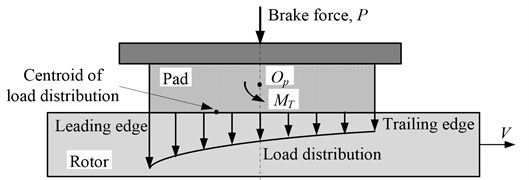
The contact load distribution on the interface between the brake pad and disc is thought to be nonlinear due to the status of the friction contact surface and the variation of friction force attributed to the time dependent friction coefficient or time dependent normal brake force or both. The load distribution can be depicted by a hyperbolic function, and the pressure on the leading side is larger than that on the trailing side as illustrated in Fig. 1 [3, 13]. Therefore the position of the resultant contact force may not coincide with the centroid of the surfaces. The eccentric contact force and the friction force between the brake pad and disc may induce angular moment around the pad's centroid, which consequently leads to nonlinear contact load distribution and the variation in effective brake force.
Fig. 1Nonlinear (hyperbolic) load distribution on the contact surface
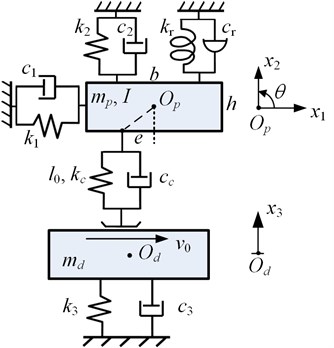
Considering the nonlinear load distribution on the contact surface, a lumped parameter model of four DOFs with contact stiffness and variable position of contact point is proposed, as shown in Fig. 2. The brake pad is modeled with three degrees of freedom including two translational motion (, ) in tangential and normal direction, respectively, and one rotational motion () in - plane around the centriod of the brake pad . Two orthogonal linear translational spring-damper elements (, and , ) and one linear rotational spring-damper element (, ) link the centriod of the brake pad to the ground. The length and thickness of the pad are denoted by and , respectively. The disc is attached to ground with one linear spring-damper element (, ) and can only move in normal direction representing its out-of-plane vibration (). It is assumed that the brake pad contacts with the disc rotating at a constant tangential velocity on a single point with contact stiffness and damping , and the initial brake force on brake pad is simulated with a pre-compressed length () of the contact spring. The deviation between the contact point and centriod of the brake pad along the direction of is denoted by , which is zero at the center of the contact surface, negative at the leading side and positive at the trailing side. The contact force between the pad and disc simulated by spring and damper only exists when the pad is in contact with the disc, but comes to zero when the interfaces separate from each other. In this way, the nonlinear property of the contact loss is introduced.
Fig. 2The four-degree-of-freedom disc brake model
According to Newton’s second law and noting that the deviation depicted in Fig. 2 is negative, the equations of motion of the brake system can be written as:
where, and represent the contact force and friction force between the two contact surfaces, respectively. The contact loss nonlinearity and the discontinuity of friction force at the zero relative velocity are both described with a “sign” function and are written as:
where, is the distance between the contact point couple of pad and disc; is the relative tangential velocity between the pad and disc; is the external net force applied on the pad in the stick phase, and the static friction force.
In our study, two friction models as shown in Fig. 3 will be applied and discussed, respectively. One is the Coulomb friction model (), where the friction coefficient is constant. The other is the Stribeck friction model [14], where the friction coefficient is defined as a function of relative velocity with negative slope. Both of the friction models are nonlinear function of the direction of relative velocity due to discontinuities at the zero relative velocity, but the Stribeck friction model introduces another nonlinear characteristic of the friction coefficient and is formulated as:
where, represent the static friction coefficient, kinetic friction coefficient, and exponential decay coefficient, respectively.
Fig. 3a) Dynamic friction force for Coulomb friction model and b) Stribeck friction model
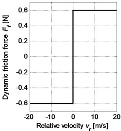
a)
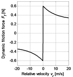
b)
3. Linear stability analysis based on the complex eigenvalues
3.1. Linear model and the Jacobian matrix
The system stability near the equilibrium state can be investigated by the linearized model using the complex eigenvalue analysis method. The real part of the complex eigenvalue has been used as a squeal propensity index in brake squeal analysis, because the negative real part indicates a stable mode as the vibration magnitude decays with time, and the positive real part represents an unstable mode as the vibration magnitude grows with time (i.e. self-excited vibration is generated).
For small perturbation around the steady sliding state, it may be assumed that the brake pad keeps in contact with the disc all the time and the direction of friction force remains the same. It is note that deviation e of the contact force location is negative for the steady sliding state in our model (Fig. 2). Therefore, the linear equations of motion of the brake system may be formed compactly as:
where:
where are mass, damping and stiffness matrices, respectively, and and are displacement and force vectors, respectively.
For the following derivation, the Stribeck friction model is introduced to simulate the falling characteristic of friction coefficient between the sliding contact surfaces. The Stribeck friction model is a nonlinear function of the relative velocity between the contact surfaces, therefore it needs to be linearized about the equilibrium point to derive the stiffness and damping matrices of the linear model. And the stiffness and damping matrices for Coulomb friction model will be obtained by setting .
First, the equilibrium state of the system is defined when there is no dynamic vibrations of pad and disc, that is , , (1, 2, 3), , . The friction coefficient in steady sliding state is assumed to be . Then the equilibrium point can be solved from:
where:
are the stiffness matrix, displacement and force vector at the equilibrium state, respectively.
Therefore, the coordinates of the equilibrium point is obtained as:
Let represent the small perturbation about the equilibrium point , so the response near the equilibrium point may be written as:
Through the coordinate transformation as Eq. (8), the original point is transformed to the equilibrium point which becomes the original point of the new coordinates denoted by The Stribeck friction model is now Linearizing it around the equilibrium point in the static equilibrium coordinates by Taylor series expansion, we can get:
Ignoring the high-order items, the linearized friction model should be:
where, , and .
Eq. (10) reveals the fact that the friction coefficient increases when the tangential vibration velocity of the pad rises (i.e., the relative velocity between the pad and disc decreases), which represents the falling characteristic of friction coefficient.
Substituting Eqs. (6), (8), (10) into Eq. (5) and omitting high-order terms yields the governing equations of motion of the system with falling characteristic of friction coefficient around its equilibrium point that can be compactly written as:
where the damping matrix and displacement vector of the system with Stribeck friction model are given by:
in which:
The remaining quantities are as defined earlier.
The inclusion of the friction forces results in asymmetric coupling items of the stiffness and damping matrices, which could be the root cause of the system instability.
To obtain the eigenvalues of the system, Eq. (11) is rewritten as the state equations of motion:
where the Jacobian matrix and state variable vector are given by:
Then the complex eigenvalues of the system with falling characteristic of friction coefficient can be calculated through the Jacobian matrix . And as mentioned before, Jacobian matrix for the Coulomb friction model can be obtained by setting .
3.2. Parametric studies
The parametric studies are performed through the simulation method to determine the stability conditions of the system, which provides significant guidance on silent brake system design. It has been mentioned in section 3.1 that the real part of the complex eigenvalue can be taken as the squeal propensity index. Positive real part indicates the presence of system instability and the magnitude of the real part represents the level of system instability, i.e., larger real part indicates greater likelihood of brake squeal. Therefore only the unstable modes with positive real parts will be analyzed in the subsequent parametric studies. The parameters of interest are: friction coefficient, the position of the contact point, the thickness of the pad, the contact stiffness and damping, the normal spring stiffness and damping of the pad and disc.
Fig. 4Effect of friction coefficient on the system stability
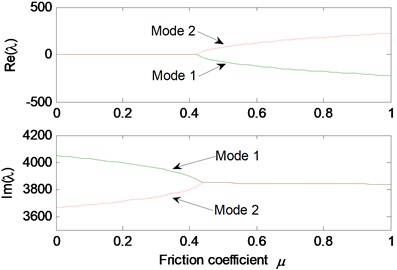
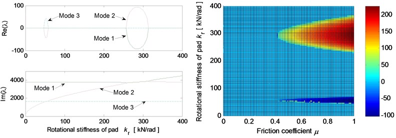
The basic parameter values for the stability analysis of the linear model are given as 1×10⁸ N/m, 1×10⁷ N/m, 3×10⁵ Nm/rad. All the damping is firstly set to 0. First, the parametric studies are conducted for Coulomb friction model. The real and imaginary parts of the complex eigenvalues are calculated for different friction coefficient and depicted in Fig. 4. It should be noted that only the unstable modes are presented here and in the following analysis. For friction coefficients smaller than 0.42, mode 1 and mode 2 are stable since the real parts of their complex eigenvalues are equal to zero. But at the real parts diverge into positive and negative branches, meanwhile, the two branches of the imaginary parts merge together. This results in mode-coupling instability of the system.
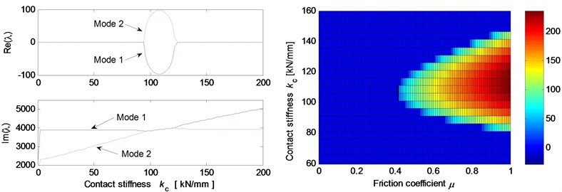
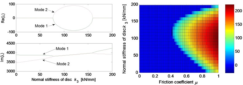
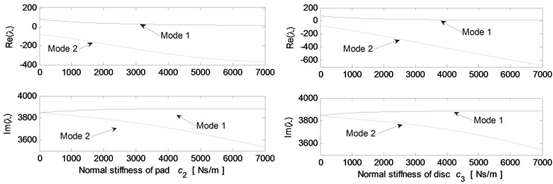
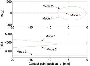
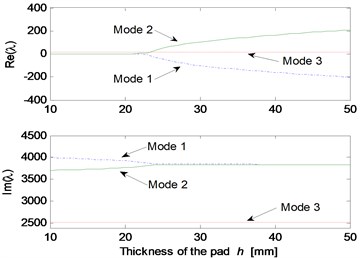
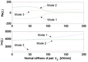
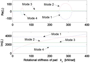
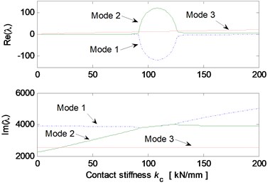
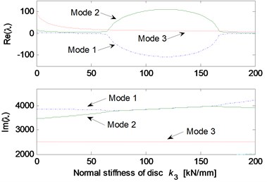
Fig. 5 shows the effects of different system parameters on the mode-coupling instability. The left Figures illustrate the real and imaginary parts of the complex eigenvalues versus the parameter values where the friction coefficient is all set to be 0.5. The right Figures are called as stability maps showing the stability/instability regions for various parameters versus friction coefficient. For the stability map, the color bar gives the value of the real part of the eigenvalues. It can be observed from the stability maps that the friction coefficient has significant influence on the range of parameter values leading to unstable system, and the greater the friction coefficient between the contact surfaces is, the larger the unstable parameter value range becomes. Fig. 5(a) demonstrates that small deviation of the contact point from the center of the contact surface will cause the system mode-coupling instability. However, system instability is not going to happen if the deviation is large enough. Fig. 5(b) shows that the thick pad (thicker than 25 mm in this study) is liable to cause system instability. But large normal stiffness of pad stabilizes the system as shown in Fig. 5(c). The rotational stiffness of pad can cause more complicated behaviors of the system. As shown in Fig. 5(d), mode 2 couples with mode 3 first and then comes to couple with mode 1 as the rotational stiffness of pad increases. As for the contact stiffness and the normal stiffness of disc, their influences on system stability is not monotonic as shown in Fig. 5(e) and 5(f), respectively. As the contact stiffness and the normal stiffness of disc increase, the mode-coupling instability occurs. However, as the contact stiffness and the normal stiffness of disc increase further, the mode-coupling phenomenon disappears and the system comes back to stable again. Fig. 5(g) shows the effects of damping of disc and pad on system stability. It is observed that the mode-coupling phenomenon disappears when damping is added to pad or disc, and increasing damping makes the system more stable, which demonstrates that adding damping on the pad or disc helps to depress high frequency brake squeal.
Fig. 5Effect of parameters on the system stability for Coulomb friction model (left: coupling modes, μ=0.5; right: stability map of parameters versus friction coefficient): a) contact point position; b) thickness of pad; c) normal stiffness of pad; d) rotational stiffness of pad; e) contact stiffness; f) normal stiffness of disc; g) normal damping of pad and disc
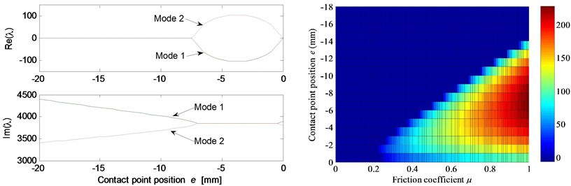
a)
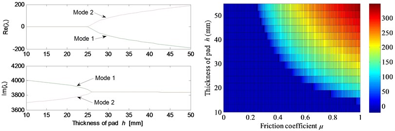
b)
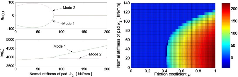
c)
d)
e)
f)
g)
Fig. 6Effect of parameters on the system stability for Stribeck friction model: a) disc velocity; b) decay coefficient of Stribeck friction model; c) contact point position; d) thickness of pad; e) normal stiffness of pad; f) rotational stiffness of pad; g) contact stiffness; h) normal stiffness of disc
a)
b)
c)
d)
e)
f)
g)
h)
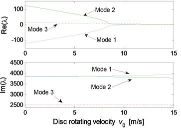
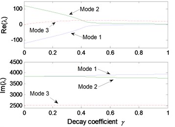
The parametric study results for Stribeck friction model are shown in Fig. 6. The static and kinetic friction coefficients of Stribeck model are set to be 0.6 and 0.3, respectively. Fig. 6(a) illustrates the influence of initial velocity of disc on the system stability. It can be observed that mode-coupling instability takes place at low disc velocity, which demonstrates that brake squeal tends to occur at low vehicle speed. Fig. 6(b) shows the influence of decay coefficient of Stribeck model on the system instability. The disc rotating velocity and decay coefficient are chosen as 2 m/s and 0.1, respectively, to conduct the stability analysis for other parameters, and the results are shown in Fig. 6(c)-6(h). Similar mode-coupling behaviors of the system are observed compared to the results obtained for Coulomb friction model. However, a wider range of the parameter values leading to system instability is observed, and more unstable modes emerge, such as mode 3 and mode 4. This indicates that the falling characteristic of friction coefficient versus relative velocity leads to more system dynamic instability, which increases the brake squeal propensity.
4. Transient response and stability analysis of the nonlinear model
The stability analysis of the linearized brake system gives an approximation of the brake squeal generation conditions and is more economical than the full transient analysis using numerical approaches. However, for deeper understanding, we have to use numerical transient analysis taking into account the friction and contact loss nonlinearities. In transient simulation analysis, the time dependence of friction force and the contact status between disc and pad can be readily incorporated into system equations, which is helpful to understand the evolutive dynamic behaviors of both disc and pad.
As presented in section 2, the disc brake model established in this paper has two kinds of nonlinear characteristics. One is the nonlinear relationship between the friction coefficient and relative velocity depicted by the Stribeck friction model, and the discontinuity of friction force existing at the zero relative velocity. The second is the contact loss nonlinearity attributed to the separation of the interfaces. To deal with these problem in numerical simulation, two main strategies, switching method and smoothing method, have been employed in some previous researches [15, 16].
In this paper, the switching method is used to simulate the contact loss nonlinearity. Therefore, Eq. (1) of the nonlinear model are numerically solved for different cases using an event detection algorithm, i.e. two sets of equations for contact and separation cases are simultaneously solved by tracking the normal relative displacement between the pad and disc. While, the discontinuous friction force is approximated by a smoothing function with a steepness factor , which can be given by:
The increasing steepness factor improves the approximation but worsens the numerical stiffness. To avoid the numerical instability, fine time steps are required to maintain accuracy especially in the regions where the relative slip velocity close to zero and the separation of pad from disc may occur.
4.1. Dynamic behavior of brake system with Coulomb and Stribeck friction models
Since the friction force variation has been considered as one main cause leading to brake squeal by many researchers, dynamic behavior of brake system with Coulomb and Stribeck friction models are investigated firstly. For this simulation the system parameter values are picked from the stable regions resulted from the linear complex eigenvalue analysis of the linearized model with constant friction coefficient: 0.4 kg, 5×10⁻⁴ kg/m2, 0.5 kg, 0.015 m, –0.016 m, 1×10⁸ N/m, 2×10⁸ N/m, 2×10⁵ Nm/rad. However, it should be noted that some of this set of parameters are in the unstable regions obtained by the complex eigenvalue analysis of the linear model with falling characteristic of the friction coefficient.
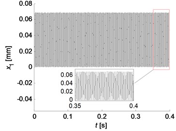
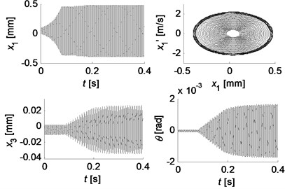
The simulation results for two friction models are shown in Fig. 7. Stable beating phenomenon of the pad in tangential direction () is observed for Coulomb friction model, while the vibration amplitudes of other degrees of freedom gradually decrease until they come to stable at the equilibrium point, which are not illustrated here for the limit space of this paper. Fig. 7(b) presents the time history of the oscillations in the direction of , and for Stribeck friction model, and the right top graph depicts the phase trajectory of , where represents the differential of . As expected, the negative damping nature of the Stribeck friction model causes transient exponential oscillatory growth in and this growth persists until the tangential vibration velocity of the pad reaches the velocity of the disc, which rapidly limits the amplitude of the oscillation in the tangential direction. At the same time, the normal vibration of the disc and the rotational vibration of the pad also show similar vibration pattens which make the behavior of the system more complicated. Although the relative displacement in normal direction and the relative velocity in tangential direction between the pad and disc are not displayed, the full contact and positive relative velocity are observed at all time for this set of parameters. Therefore, the results obtained by the nonlinear simulations are in good agreement with that obtained by the complex eigenvalue analysis of the linear model.
Fig. 7Simulation results for two friction models: a) stable beating oscillation of x1 for Coulomb friction model (μ=0.4); b) transient growth and amplitude saturation vibrations for Stribeck friction model (μs=0.6, μk=0.3), and the right top graph depicts the phase trajectory of x1
a)
b)
4.2. Complex dynamic behavior of the system with strong nonlinearities
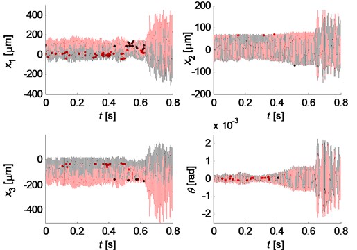
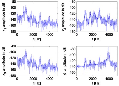
However, when the contact loss nonlinearity of the brake system is strong, unstable vibrations can be observed even for Coulomb friction model. Fig. 8 illustrates displacements and their spectra, respectively, for the parameter values: 0.4 kg, 5×10⁻⁴ kg/m2, 0.5 kg, 0.03 m, –0.006 m, 5×10⁷ N/m, 0.2 23×105 N/m. Separation between brake pad and disc is indicated by red color in the displacement history curves. The relative displacement in normal direction and the relative velocity in tangential direction between the pad and disc are demonstrated in Fig. 9. The negative relative displacement means that the pad separates from the disc, meanwhile, the negative relative velocity indicates that the friction force changes its direction. It can be observed that the brake system undergoes strong nonlinearities both of contact loss and friction force. The time histories of the displacement are not periodic or quasi-periodic, and they have very broad spectra as shown is Fig. 8(b), which may demonstrate the chaotic vibration behavior of the system even for Coulomb friction due to the strong nonlinearities.
The dynamic behavior of the system with strong nonlinearities is very sensitive to the system parameters. Some complex vibrations can be observed by setting different parameter values. Figs. 10 and 11 illustrate two kind of quasi-periodic and chaotic motions, respectively.
Fig. 8Chaotic behavior of the system with Coulomb friction: a) time histories of displacement; b) spectra
a)
b)
Fig. 9Relative normal displacement and relative tangential velocity between the pad and disc
It is found that the ratio between the normal stiffness of the pad/disc (, ) and the contact stiffness () has a significant effect on the contact loss nonlinearity of the system. Fig. 12 shows the envelop of the relative normal displacement between the pad and disc for different stiffness configurations where the disc normal stiffness is set to be 2.2, while the pad normal stiffness is changing. It can be observed that the system has strong contact loss nonlinearity characteristic when the pad normal stiffness is much smaller than the contact stiffness. As the pad normal stiffness increases, the contact nonlinearity become weaker, until no separation occurs. The same rule is also obtained for disc normal stiffness. Simulations for more stiffness configurations are conducted, and it seems that a criterion may be given for the case of keeping the pad and disc in contact. This criterion may be written as:
where is the ratio of the normal stiffness of the pad/disc and the contact stiffness depending on the system parameters. For our case, the ratio is approximately equal to 2.2.
Fig. 10Quasi-periodic motion for kc= 5×10⁷ N/m, k2= 0.2kc and k3= 2.2kc
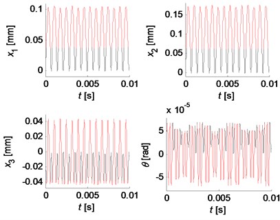
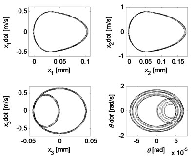
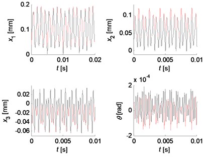
Fig. 11Chaotic motion for kc= 5×10⁷ N/m, k2= 0.6kc, k3= 2.2kc
4.3. Stick-slip vibration and influences of parameters
When the friction coefficient between the pad and disc has a falling characteristic (negative slop of friction coefficient versus velocity), stick-slip vibration may take place. It is found that the occurrence of stick-slip vibration is dependent on the tangential stiffness of the pad. Fig. 13 demonstrates the phase trajectories of the tangential behavior of the pad for three tangential pad stiffness. It can be seen that stick-slip occurs when the tangential pad stiffness is smaller, and the sticking motion phase is shorten as the tangential pad stiffness increases, until the stick-slip phenomenon disappears completely and a steady limit cycle is developed.
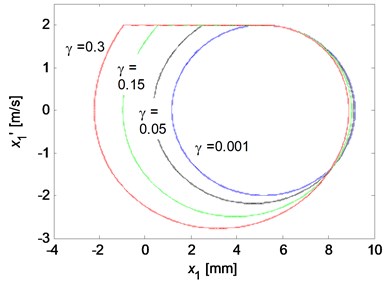
The influences of the decaying factor of the Stribeck friction model and the disc velocity on the stick-slip vibrations are then investigated. The results for various values are illustrated in Fig. 14. To be clear, Fig. 14 are depicted after the transient motions die out. It can be observed from Fig. 14(a) that no stick-slip vibration occurs and a steady limit cycle develops when the decaying factor is very small, which means the kinetic friction coefficient is almost equal to the static friction coefficient. The stick-slip vibration occurs for larger decaying factor, and as the decaying factor increases, the size of the limit cycle increases. This demonstrates that the propensity of brake squeal increases when the difference between the kinetic and static friction coefficient gets larger. Similar influence of the disc velocity on the stick-slip limit cycle is obtained as shown in Fig. 14(b). However, the stick-slip phenomenon will disappear if the disc velocity is large enough, which demonstrates that the brake squeal is more likely to generate in a relative low vehicle speed.
Fig. 12Envelop of the relative normal displacement between pad and disc (red line: k2= 2.2kc; green line: k2= 1.0kc; blue line: k2= 0.2kc; black line: time history of relative displacement for k2= 2.2kc)
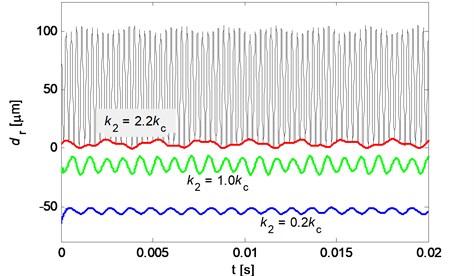
Fig. 13Phase trajectories of the tangential behavior of the pad for three tangential pad stiffness
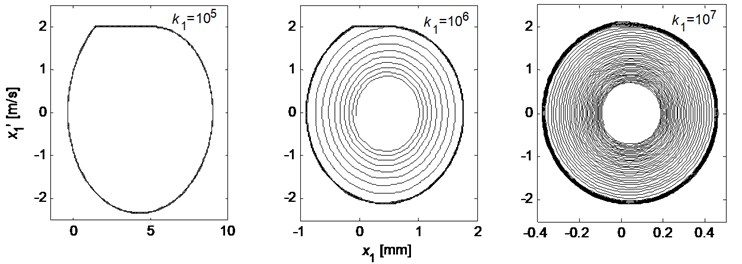
Fig. 14The limit cycle motions of x1 for various parameter values: a) the influence of decaying factor (k1= 105 N/m, v0= 2 m/s); b) the influence of the disc rotation velocity (k1= 105 N/m, γ= 0.1)
a)
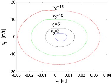
b)
5. Conclusions
To explore the mechanism of disc brake squeal, a nonlinear lumped parameter model with four DOFs is developed, including the normal and tangential translation motions and one rotational motion of the brake pad and one out-of-plane motion of the disc. The friction and contact loss nonlinearities are included in this model, as well as the nonlinear load distribution on the contact surface simulated by variable position of one single contact point. The Coulomb and Stribeck friction models are used and compared in our studies. The nonlinear equations of motion are presented and then linearized around the equilibrium point. The effects of key parameters of the brake system on stability are investigated based on the linear equations using the complex eigenvalue analysis method. Numerical solutions of the nonlinear equations are obtained to examine the transient dynamic behaviors and to find the routes to squeal of the brake system with strong nonlinearities. The observations and conclusions can be drawn as follows:
1) Mode-coupling motion is one significant mechanism to initiate the system instability and lead to brake squeal, and is exceptionally reliant on the parameter configurations of brake system. The range of parameter values leading to system mode-coupling instability is affected by the friction coefficient between the contact interface.
2) Compared to the Coulomb model with constant friction coefficient, the Sribeck friction model enlarges the unstable range of system parameters and leads to more unstable modes, which increases the brake squeal propensity due to its negative damping nature.
3) The contact loss nonlinearity may make system unstable even for constant friction coefficient. And the separation between the brake pad and disc is dependent on the ratio of normal stiffness of pad/disc and contact stiffness.
4) Nonlinear items may constrain the system to limit cycle vibrations, but also may lead to complicated quasi-periodic and chaotic motions, resulting in squeal problem, when they are strong enough.
5) The tangential stiffness of the pad and the disc velocity play important roles in the occurrence of stick-slip vibration resulting from the falling characteristic of friction coefficient.
References
-
Kinkaid N. M., O’Reilly O. M., Papadopoulos P. Automotive disc brake squeal. Journal of Sound and Vibration, Vol. 267, Issue 1, 2003, p. 105-166.
-
Chen F. Automotive disk brake squeal: an overview. International Journal of Vehicle Design, Vol. 51, Nos. 1-2, 2009, p. 39-72.
-
Dai Y., Lim T. C. Suppression of brake squeal noise applying finite element brake and pad model enhanced by spectral-based assurance criteria. Applied Acoustics, Vol. 69, Issue 3, 2008, p. 196-214.
-
AbuBakar A. R., Ouyang H. Complex eigenvalue analysis and dynamic transient analysis in predicting disc brake squeal. International Journal Vehicle Noise and Vibration, Vol. 2, 2006, p. 143-155.
-
Liu P., Zheng H., Cai C., et al. Analysis of disc brake squeal using the complex eigenvalue method. Applied Acoustics, Vol. 68, Issue 6, 2007, p. 603-605.
-
Hoffmann N., Bieser S., Gaul L. Harmonic balance and averaging techniques for stick-slip limited-cycle determination in mode-coupling friction self-excited system. Engineering Mechanics, Vol. 24, Issue 3-4, 2004, p. 185-197, (in German).
-
Sen O. T., Dreyer J. T., Singh R. An improved brake squeal source model in the presence of kinematic and friction nonlinearities. Inter-Noise, Innsbruck, Austria, 2013.
-
Shin K., Brennan M. J., Oh J. E., et al. Analysis of disc brake noise using a two-degree-of-freedom model. Journal of Sound and Vibration, Vol. 254, Issue 5, 2002, p. 837-848.
-
Popp K., Rudolph M., Kröger M., et al. Mechanisms to generate and to avoid friction induced vibrations. VDI Reports, Vol. 1736, Issue 1-16, 2002, (in German).
-
Von Wagner U., Hochlenert D., Hagedorn P. Minimal models for disk brake squeal. Journal of Sound and Vibration, Vol. 302, Issue 3, 2007, p. 527-539.
-
Massi F., Baillet L. Numerical analysis of squeal instability. International Congress of November, St. Raphael, France, 2005.
-
Joe Y. G., Cha B. G., Sim H. J., et al. Analysis of disc brake instability due to friction-induced vibration using a distributed parameter model. International Journal of Automotive Technology, Vol. 9, Issue 2, 2008, p. 161-171.
-
Oura Y., Kurita Y., Matsumura Y., et al. Influence of distributed stiffness in contact surface on disk brake squeal. SAE Technical Paper 2008-01-2584, 2008.
-
Olsson H., Aström K. J., Canudas de Wit C., et al. Friction models and friction compensation. European Journal of Control, Vol. 4, Issue 3, 1998, p. 176-195.
-
Leine R. I., Van Campen D. H., De Kraker A. Stick-slip vibrations induced by alternate friction models. Nonlinear Dynamics, Vol. 16, 1998, p. 41-54.
-
Do N. B., Bauchau O. A., Ferri A. A. Efficient simulation of a dynamic system with LuGre friction. Journal of Computational and Nonlinear Dynamics, Vol. 2, Issue 4, 2007, p. 281-289.
About this article
The authors would like to thank the financial support provided by the Natural Science Foundation of China (No. 51275022) and China Scholarship Council.
