Abstract
In this paper, a fuzzy logic controller approach is presented for twin rotor multi-input-multi-output (MIMO) system in order to improve the control of pitch and yaw motions under hovering conditions. Twin rotor MIMO system resembles a helicopter model in some common aspects like cross coupling of pitch and yaw motions. The proposed approach is compared with another control strategy by simulations for a nonlinear two degrees of freedom twin rotor model. Set point reaching and trajectory tracking behaviours of the TRMS are analysed by time and step response characteristics. Results of time and step responses indicate that fuzzy logic controller improves set point reaching and trajectory tracking performance of the closed loop system.
1. Introduction
Twin rotor multi-input-multi-output (MIMO) system is a fundamental model for studying the hovering dynamics of a helicopter having common behaviour in some aspects such as cross coupled pitch and yaw motions. Over the last decade, several studies have been carried out on modelling and controlling pitch and yaw motion of twin rotor MIMO system (TRMS) [1-13]. A recent investigation for TRMS is a design and application of a fault-tolerant control strategy to the twin rotor system manufactured by Feedback Instruments Limited [1]. Rotondo et al. had proposed a quasi-LPV modelling, identification and control approach for the same test rig in another study [7]. Wen and Lu developed a robust deadbeat control technique and applied to two SISO systems decoupled from the identified system [8]. Yang and Hsu presented a novel adaptive control approach based on the backstepping concept and demonstrated the applicability of the proposed control scheme with computer simulations and experiments [9].
Most of the time, the system model of the plant is nonlinear or unknown. TRMS includes nonlinear and coupled effects that disrupt pitch and yaw motions simultaneously. The intelligent control methods draw attention to overcome this issue. Fuzzy logic control is one of the intelligent control methods based on the fuzzy logic theory which was first presented by Zadeh [14]. Soh et al. designed and implemented a fuzzy logic controller to Quanser’s two degree of freedom helicopter [2]. In the proposed controller, the pitch or yaw position error and the rate of change of pitch or yaw position derivative error were chosen for the input variables and the output variable was the input control voltage of the related rotor motor that effects on pitch or yaw motion. Mohammadzaheri and Chen designed a neuro-predictive control with fuzzy compensator in order to control the yaw angle of a model helicopter [10]. The control behaviour was improved by the proposed controller. Tao et al. designed parallel distributed fuzzy LQR controller in order to control the positions of the pitch and yaw angles in TRMS [11]. The desired values were achieved for the yaw and pitch positions. Ramli et al. carried out an investigation on active force control to characterize TRMS and integrated an intelligent control method to optimize the performance of TRMS [12]. Recently, Jahed and Farrokhi designed an adaptive fuzzy controller to stabilize TRMS in a desired position [13]. The adaptive parameters of the fuzzy controller are using the gradient descent algorithm in order to increase the robustness. The classical fuzzy logic controllers act as sliding mode controllers with a boundary layer over a sliding line along the diagonal of the rule base. Thus, the stability of the closed loop system can be obtained from the similarity between classical fuzzy logic control and sliding mode control [15].
The motivation of this study is originated from the growing interest in developing unmanned aircraft systems [16] and the similarities between TRMS and helicopter dynamics. This study addresses the pitch and yaw motion control of two degrees of freedom TRMS with a fuzzy logic approach. The control design presented in this paper is based on an active suspension control strategy [17] and adapted on a TRMS model. The paper is organized as follows; the nonlinear mathematical model of TRMS which is obtained by Lagrange method is introduced in Section 2. Section 3 describes the strategy and the design of the fuzzy logic controller. Then, numerical results are given with a comparison of another control strategy in Section 4. Finally, the paper is concluded in Section 5.
2. Nonlinear mathematical model of TRMS
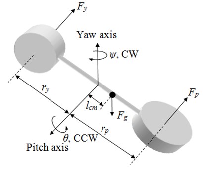
Physical model of TRMS is shown in Fig. 1. It consists of two propellers placed on a lever arm at perpendicular planes. They are driven by two DC motors. TRMS can rotate freely around yaw and pitch axes. and are the pitch and yaw thrust forces generated by the propellers. The forces are functions of the input voltages and controlling the pitch and the yaw motions of the system. The rotation of the each propeller also causes cross coupling load torques on the motor shafts that occur at the perpendicular axes in terms of input voltages. and are the distances from pitch and yaw rotors to the pivot point of the system. is the center of mass length along TRMS body from pitch axis. is the force due to gravity acting through the centre of mass.
Fig. 1Physical model of TRMS.
Lagrange’s method is used to obtain the system’s equation of motion. and are generalized coordinates corresponding to pitch and yaw angles, respectively. The equations of motion of the system are given in Eq. (1) and (2):
where, and are the equivalent moments of inertia about pitch and yaw axes. and are the equivalent viscous damping constants about pitch and yaw axes. is the total moving mass of the TRMS. and are thrust torque constants of pitch and yaw motor propeller actuators acting on pitch axis. and are thrust torque constants of the same actuators above yaw axis. and are the control voltages of pitch and yaw motors respectively. Model parameters are given in Table 1 [18].
Table 1Model parameters
Parameter | Value | Parameter | Value |
0.0384 kg·m2 | 0.0432 kg·m2 | ||
0.8000 N·ms/rad | 0.3180 N·ms/rad | ||
0.2041 N·m/V | 0.0068 N·m/V | ||
0.0720 N·m/V | 0.0219 N·m/V | ||
0.1857 m | 1.3872 kg |
3. Fuzzy logic controller design
The aim of the study is to improve the set point reaching and trajectory tracking behaviour of the TRMS for the pitch and yaw angle changes. Thus, a fuzzy logic controller with three inputs and a single output is designed for a single rotor by adapting from an active suspension controller [17]. Fuzzification, inference and defuzzification are three main steps in fuzzy logic control. The membership functions are described for the input and output variables by converting the crisp variables to fuzzy variables in the first step. Then, the linguistic expressions are used to form the rules that constitute the rule base in the second step. In general, these rules are in the following form with n inputs and a single output for a fuzzy controller:
In the last step the fuzzy variables are converted to crisp values with an appropriate defuzzification method. In this study the centroid method is preferred for the defuzzification of the fuzzy variables, since it is widely used in the literature.
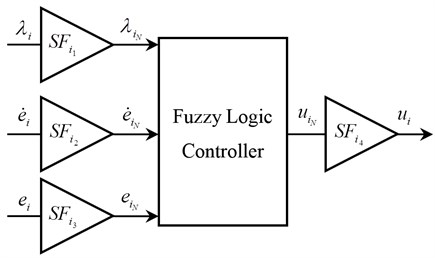
The structure of the controller is given in Fig. 2. The inputs of the controller are chosen as pitch or yaw position error , derivative of position error , and the combination of these two inputs . The subscript denotes to either pitch () or yaw () positions and indicates that the variables are normalized. is the weighting factor of the defined combination for each rotor. The output is the control voltage of the pitch or yaw motor.
Fig. 2Structure of the proposed controller
This strategy is applied for both pitch and yaw motors independently. Block diagram of the closed loop control system is demonstrated in Fig. 3. , , and are the desired pitch and yaw positions and derivative of desired pitch and yaw positions, respectively.
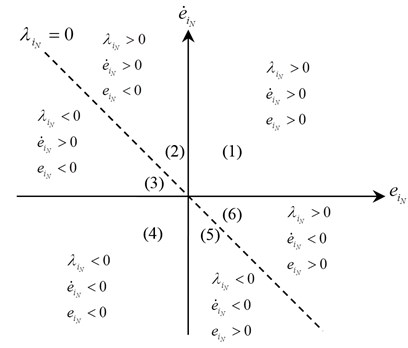
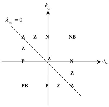
In order to construct the rule base, the sign of the input variables are considered on the vs. plane as shown in Fig. 4(a) and the rules are given on the same plane in Fig. 4(b). There exits six regions on the vs. plane when the input value divides the plane diagonally. The input variable owns a crucial part to satisfy the aim of the control strategy. When takes negative values, that means either a negative pitch or yaw position error exists or the position error tends to be negative because of the large angular acceleration. Thus, during this time the control voltage should be positive to generate positive thrust force, which rotates TRMS body to the related reference. Similarly, for the positive values of , a negative thrust force should be applied to the related axis of TRMS body. When assumes approximately zero values, which agrees with the design requirements, the control inputs are approximately zero. For the nonzero values of , the other two inputs of the fuzzy controller give information about the location of the system states. If the states are far away from 0 line, it needs greater effort to reach 0 line. For example, if all the inputs are positive (1st region in Fig. 4(a)), i.e., a positive pitch or yaw position error exists and the related axis is moving away from reference, then the control input is selected to be negative big. This choice of control input forces the axis of TRMS body to be closer to the reference value, which results in zero position error and zero angular velocity for TRMS axes. Suppose, however, that the position error is positive and the angular velocity is negative and is negative (5th region in Fig. 4(a)), then the control voltage is selected to be zero since the internal dynamics of the system force and the position error to be zero, spontaneously. By using similar manner, the rule table of the controller inputs-output is constructed and given in Table 2.
Fig. 3Block diagram of the closed loop control system
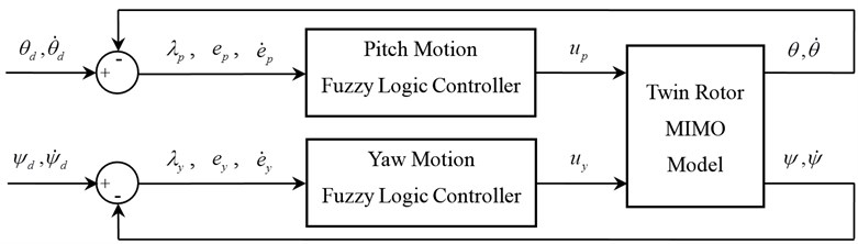
Fig. 4a) The sign of the input variables, b) Graphical representation of output variable
a)
b)
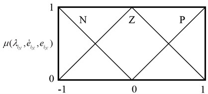
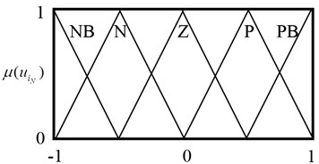
Fig. 5(a) and (b) demonstrate the triangular membership functions used for the input and output variables. NB, N, Z, P and PB represent negative big, negative, zero, positive and positive big, respectively. The membership functions are constructed according to the graphical representation of inputs and output variables as shown in Fig. 4(a) and (b).
Input and output membership functions are set on the [–1, 1] closed interval. The crisp values to the corresponding fuzzy values are tuned by the scaling factors (). The relations between the normalized and actual values are given in Eq. (4)-(7) as shown in Fig. 3:
Fig. 5a) Membership functions of input variables; b) Membership functions of output variable
a)
b)
Table 2Rule table of the controller
Inputs | Output | ||
P | P | P | NB |
P | P | Z | N |
P | P | N | Z |
P | Z | P | N |
P | N | P | Z |
Z | P | N | Z |
Z | Z | Z | Z |
Z | N | P | Z |
N | P | N | Z |
N | Z | N | P |
N | N | P | Z |
N | N | Z | P |
N | N | N | PB |
The rules are arranged by applying certain control inputs to render to be zero. Thus, the states are kept in the region and internal dynamics of the system render the error and derivative of error to be zero. Therefore, all the states of the system are regulated to be zero by the constructed rule table. In fact, it is possible to write 27 rules when three inputs are used. However, some of them are not physically realizable. For instance, if the position error and the derivative of the position error are both negative, the first input variable, , cannot have a positive value. Thus, certain input combinations are not used during the construction of the rule table, which reduces the size of the rule base and decreases the computation time.
4. Numerical results
In order to evaluate the set point reaching and trajectory tracking performances of the proposed controller, a square and a sine waveforms are defined consecutively as the reference trajectory for pitch and yaw motions. Then, the proposed fuzzy controller is compared with another controller strategy for various cases under different reference trajectories. The other controller includes the combination of a feed-forward controller and a LQR PID position controller (FF+LQR+PID) which is given in the laboratory manual of Quanser’s two degrees of freedom helicopter [18]. The structure and the parameters of feed-forward and LQR PID position controllers are given in Appendix. In Table 3, scaling and weighting factors of the proposed fuzzy controller are given. They are tuned by trial and error.
Table 3Proposed controller parameters
Parameter | Value |
, | 1/3 |
, | 1/40 |
, | 9/10 |
, | 4000 |
, | 2 |
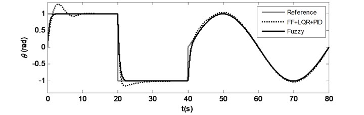
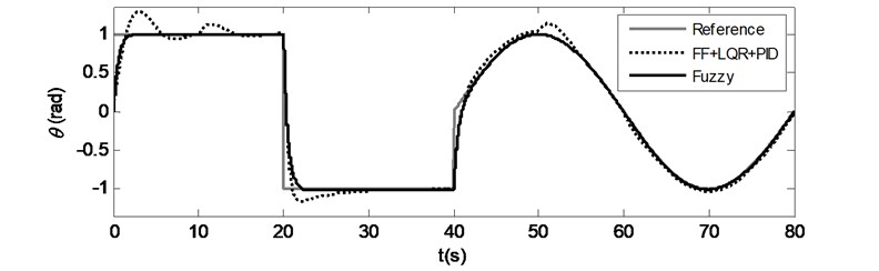
Three cases are considered in the comparison of the two controllers. Each case includes different trajectory combinations. In all cases the twin rotor is at the starting point where the pitch and yaw angle initial values are set to zero radians. In the first case, the desired pitch and yaw tracking path is chosen as a square and a sine waveforms consecutively in Fig. 6, whose frequency and amplitude are 0.025 Hz and 1 rad for the total duration of 80 s.
Fig. 6Case 1: Time responses for a) Pitch motion, b) Yaw motion
a)
b)
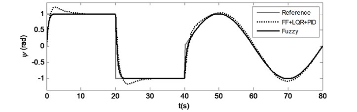
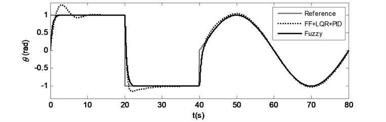
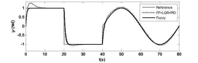
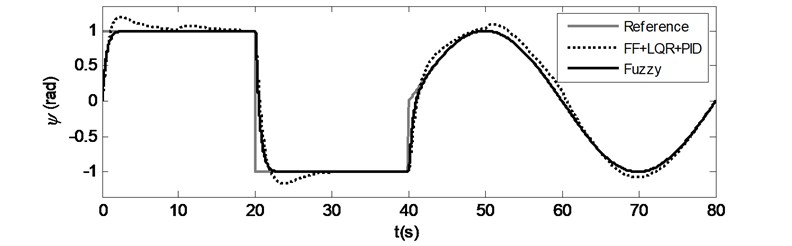
For the second and third cases, only one tracking path is chosen as above mentioned waveforms and the other desired tracking path is set to zero radians in Fig. 7 and 8. The set point reaching and trajectory tracking behaviour can be observed by time responses in Fig. 6-8. In all cases, the proposed fuzzy controller demonstrates satisfactory set point and trajectory tracking performance. When the time responses of both controllers are examined, it is observed that the rise times are almost preserved for pitch and yaw motions in all cases and moreover the proposed controller provides shorter settling times without overshoot. On the one hand, in Fig. 7(b), while the TRMS is tracking the pitch trajectory and also trying to maintain the yaw reference at zero radians, the pitch thrust forces cause cross coupling loads on the yaw motion for the compared controller that can be observed at the beginning of the yaw motion between 0 and 10 seconds, between 20 and 30 seconds and between 40 and 80 seconds. The same effect can be observed in Fig. 8(a) with a little difference. Yaw thrust forces causes less cross coupling loads when compared to pitch trust forces. These effects are observed and valid for the comparison controller. On the other hand, the proposed controller prevents and minimizes the cross coupling effects that can be observed in Fig. 7(b) and Fig. 8(a) as well.
Fig. 7Case 2: Time responses for a) Pitch motion, b) Yaw motion
a)
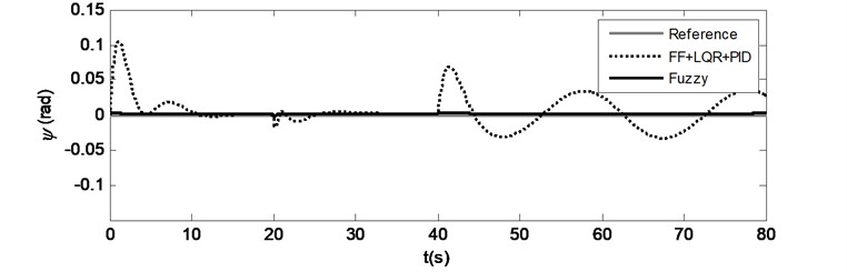
b)
Fig. 8Case 3: Time responses for a) Pitch motion, b) Yaw motion
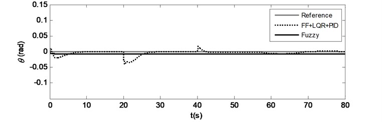
a)
b)
Step response characteristics for all cases are obtained from the square waveform parts of the time responses for the first 20 s duration of the simulations and given in Table 4. As it is observed from the time responses, the rise times of all cases for both methods are almost similar. There are no overshoots occurred in the proposed controller’s results. The steady-state error percentages of the proposed controller for all cases are greater than the compared ones, but they are less than 0.7 % and negligible. It is also noticed that the settling times and mean-squared errors are decreased significantly in all cases by the proposed controller.
A disturbance input as shown in Fig. 9 is applied to the forward path of the horizontal and vertical control loops in order to evaluate the controller’s robustness against external disturbances. Time responses of pitch and yaw motions are simulated for Case 1 and the results are shown in Fig. 10(a) and (b). While the LQR based controller is affected by the disturbance, the proposed controller shows better external disturbance rejection and more robustness. The effects of the external disturbance can be clearly seen, if Fig. 6(a), (b) and Fig. 10(a), (b) are compared. The position error of the LQR based controller is increased as the disturbance is applied. On the other hand the proposed controller preserves the tracking without any distortion.
Fig. 9Applied disturbance to each axis
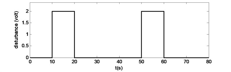
Fig. 10Case 1: Time responses for a) Pitch motion, b) Yaw motion under external disturbance
a)
b)
Table 4Comparison of the step response characteristics
Pitch () and yaw () motion characteristics | Case 1 | Case 2 | Case 3 | ||||
Fuzzy | FF+LQR+PID | Fuzzy | FF+LQR+PID | Fuzzy | FF+LQR+PID | ||
Rise time (s) | 1.222 | 1.282 | 1.226 | 1.289 | – | – | |
1.188 | 0.978 | – | – | 1.193 | 0.953 | ||
Overshoot (%) | – | 28.51 | – | 28.85 | – | – | |
– | 20.20 | – | – | – | 27.88 | ||
Settling time (s) | 1.596 | 8.410 | 1.600 | 8.454 | – | – | |
1.529 | 7.069 | – | – | 1.531 | 6.816 | ||
Steady-state error (%) | 0.3730 | 0.0456 | 0.3728 | 0.0448 | 0.6840 | 0.0001 | |
0.1151 | 0.0035 | 0.1151 | 0.0022 | 0.1932 | 0.0011 | ||
Mean-squared error (rad2) | 0.0149 | 0.0287 | 0.0152 | 0.0295 | 0.00005 | 0.00006 | |
0.0148 | 0.0225 | 0.000002 | 0.0009 | 0.0151 | 0.0272 | ||
5. Conclusions
A fuzzy logic controller adaptation on a twin rotor MIMO system is introduced. The proposed controller is compared with an LQR based control strategy in order to show improvements of the set point reaching and trajectory tracking performance. The numerical results show that the fuzzy controller exhibits a promising behaviour and satisfactory set point reaching and trajectory tracking performance in terms of improving the control of pitch and yaw motions simultaneously. The cross coupling effect is also reduced and better control with good robustness against external disturbance is provided by the proposed controller.
References
-
Witczak M., Puig V., de Oca S. M. A fault-tolerant control strategy for non-linear discrete-time systems: application to the twin-rotor system. International Journal of Control, Vol. 86, Issue 10, 2013, p. 1788-1799.
-
Soh A. C., Abdul Rahman R., Md Sarkan H., Yeo L. T. Intelligent control of twin-rotor MIMO system using fuzzy inference techniques. International Review of Aerospace Engineering, Vol. 6, Issue 1, 2013, p. 28-39.
-
Shih C. L., Chen M. L., Wang J. Y. Mathematical model set-point stabilizing controller design of a twin rotor MIMO system. Asian Journal of Control, Vol. 10, Issue 1, 2008, p. 107-114.
-
Ahmad S. M., Chipperfield A. J., Tokhi M. O. Parametric modelling and dynamic characterization of a two-degree-of-freedom twin-rotor multi-input multi-output system. Proceedings of the Institution of Mechanical Engineers, Part G: Journal of Aerospace Engineering, Vol. 215, Issue 2, 2001, p. 63-78.
-
Rahideh A., Shaheed M., Huijberts H. Dynamic modelling of a TRMS using analytical and empirical approaches. Control Engineering Practice, Vol. 16, Issue 3, 2008, p. 241-259.
-
Juang J. G., Lin R. W., Liu W. K. Comparison of classical control and intelligent control for a MIMO system. Applied Mathematics and Computation, Vol. 205, Issue 2, 2008, p. 778-791.
-
Rotondo D., Nejjari F., Puig V. Quasi-LPV modeling, identification and control of a twin rotor MIMO system. Control Engineering Practice, Vol. 21, Issue 6, 2013, p. 829-846.
-
Wen P., Lu T. W. Decoupling control of a twin rotor MIMO system using robust deadbeat control technique. IET Control Theory Appl., Vol. 2, Issue 11, 2008, p. 999-1007.
-
Yang J. H., Hsu W. C. Adaptive backstepping control for electrically driven unmanned helicopter. Control Engineering Practice, Vol. 17, Issue 8, 2009, p. 903-913.
-
Mohammadzaheri M., Chen L. Intelligent predictive control of a model helicopter’s yaw angle. Asian Journal of Control, Vol. 12, Issue 6, 2010, p. 667-679.
-
Tao C., Taur J., Chen Y. Design of a parallel distributed fuzzy LQR controller for the twin rotor multi-input multi-output system. Fuzzy Sets and Systems, Vol. 161, Issue 15, 2010, p. 2081-2103.
-
Ramli H., Meon M., Mohamed T., Isa A., Mohamed Z. A Fuzzy-active force control architecture based in characterizing nonlinear systems’ behavior. Procedia Engineering, Vol. 41, 2012, p. 1389-1397.
-
Jahed M., Farrokhi M. Robust adaptive fuzzy control of twin rotor MIMO system. Soft Computing, Vol. 17, Issue 10, 2013, p. 1847-1860.
-
Zadeh L. A. Fuzzy sets. Information and Control, Vol. 8, 1965, p. 338-353.
-
Palm R. Sliding mode fuzzy control. Proceedings of the IEEE International Conference on Fuzzy Systems, San Diego, CA, 1992, p. 519-526.
-
Kendoul F. Survey of advances in guidance, navigation, and control of unmanned rotorcraft systems. J. Field Robotics, Vol. 29, Issue 2, 2012, p. 315-378.
-
Taskin Y., Hacioglu Y., Yagiz N. The use of fuzzy-logic control to improve the ride comfort of vehicles. Strojniski Vestnik-Journal of Mechanical Engineering, Vol. 53, Issue 4, 2007, p. 233-240.
-
Quanser Inc. Quanser 2 DOF Helicopter User and Laboratory Manuals, Revision 2.3.
About this article
