Abstract
The nonlinear feedback cascade model of the underactuated translational oscillators with rotating actuator is obtained through a collocated partial feedback linearization and a global change of coordinates. A nonlinear controller is designed with the backsteping technology, which treats the state variables as virtual control inputs to design the virtual controllers step by step. The system stability is proved with the Lyapunov stability theorem. The simulation results show the system under any initial states can be asymptotically stabilized to the origin and the controller has a good control performance.
1. Introduction
The TORA (translational oscillators with rotating actuator) is a classical underactuated mechanical system, which is composed of a non-actuated translational oscillators and an actuated pendulum. It was developed as a simplified model of a dual spin spacecraft [1]. One research motivation to control the TORA comes from the possible use to suppress the translational vibration with a rotational actuation. The other is an independent interest to control the TORA as a benchmark problem in the nonlinear control design.
The control problem on the TORA has attracted a considerable amount of attentions from many researchers. Some focus on the intelligent design methods [2-4] and some focus on the nonlinear design methods [5-11]. Among the intelligent design methods, a self-tuning fuzzy sliding mode control is proposed [2-3] and there are some fuzzy rules and parameters to be preset. A neural network controller is proposed with SPSA Algorithm [4] and a time-consuming learning process is needed. Among the nonlinear design methods, the energy-based design [5-7], the backstepping design [8-9] and sliding mode based design [10], the design processes and the obtained controllers are relatively cumbersome. A comparison study of nonlinear control techniques for the TORA is performed [5].
In this paper, the TORA system is transformed into a nonlinear feedback cascade system through a collocated partial feedback linearization and a global change of coordinates. Then a nonlinear backstepping design method is proposed. The design procedure treats the state variables as virtual control inputs to design the virtual controllers step by step, and the system stability is proved via the Lyapunov stability theorem.
2. The TORA system model
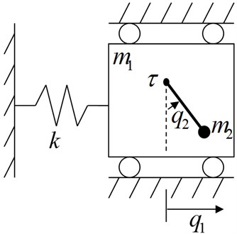
The TORA is shown schematically in Fig. 1. The oscillator consists of a cart of mass connected to a fixed wall by a linear spring of stiffness . The cart is constrained to have one-dimensional travel and its position is . The rotational actuator with the output torque is attached to the cart and it has a pendulum with the equivalent mass , the rotate radius , the moment of inertia and the rotate angle . Since the rotating torque can not drive the cart directly, it is a benchmark example of the underactuated mechanical system, which has one control input and two configuration variables (, ), and its Euler-Lagrange equations of motion can be obtained as:
Fig. 1TORA system configuration
Since the partial feedback linearization technology proposed by Spong [12] can simplify the system dynamics. The following collocated partial feedback linearization is adopted:
and it can simplify the dynamics of the shape variable as:
Olfati-Saber proposed a global change of coordinates [13] such as:
It can transform the system dynamics into a nonlinear system as:
Therefore, the system model of TORA can be described with a nonlinear feedback cascade model [14] as:
3. The nonlinear controller design through backstepping
Since the model of TORA can be transformed into a cascade nonlinear system through the collocated partial feedback linearization (2) and the global change of coordinates (3), a nonlinear controller can be designed with the backstepping technology [14]. The design process is:
Step 1.
From the dynamic equation of state in the TORA system model (5):
It can be seen that only is in the dynamic equation (6) of state . So can be looked as the virtual control input to Equation (6) to control the system state and . A reference trajectory is defined for to track as:
which leads to an error defined as:
where, and are positive constants that are chosen such that:
is asymptotically stable at .
The dynamic Equation (6) of state can be described as:
Define , , . So the Equation (8) is written as:
According to the control theory for the linear time-invariant system [15], the choose of and can implies the existence of a positive definite symmetry matrix and so that:
Consider a scalar positive definite Lyapunov function given by:
Its time derivative is given by:
We note that the variable enters the right hand side of Equation (9). We now proceed to look as the control variable and design a reference trajectory for it to make the second term of right hand in Equation (9) be non-positive.
Step 2.
In step 1, the time derivative of the Lyapunov function is obtained in Equation (9). In order to make the be negative definite, the state is looked as the virtual control input in Equation (9). A reference trajectory is defined as:
The tracking error for can be defined as:
So:
We modify the scalar positive Lyapunov function as:
Differentiating :
Step 3.
The system control variable enters in the right hand of the Equation (11). So, In order to make the be negative definite, we can make the following equation hold:
Such that:
Therefore, the control law can be obtained from (12) as:
Theorem 1: The TORA system described by Equation (1) is asymptotically stable under the control input (2) and the nonlinear controller (14) with the feedback cascade model (5) and the global change of coordinates (3).
Proof:
The backstepping design process has proved: the time derivative of the chosen positive definite Lyapunov function is negative definite. That is to say, the three terms of the right hand in Equation (13) is asymptotically approach to 0. Since that the first term approaches to 0, must asymptotically approach to (0,0). From the second term approaches to 0, it is known from Equation (7) that must asymptotically approach to 0. The third term approaches to 0 implies that asymptotically approach to 0. Therefore, the system states of the TORA described by Equation (5) asymptotically approach to (0,0,0,0).
The global change of coordinates (3) is an invertible transformation, which is:
It can be seen from Equation (15) that asymptotically approach to (0,0,0,0) implies that approach to (0,0,0,0). That is to say, the control input that is calculated with Equation (2), (14) and (4) can asymptotically stabilize the TORA system.
Remark 1: There is a singularity when in the controller (14). The method to deal with the singularity is: a linear controller is designed through the LQR method [15] with the linearized system around for the TORA system:
The controller switch between the nonlinear controller (14) and the linear controller (16) according to the system state .
Remark 2: Only three steps are needed to obtain the nonlinear controller with the backstepping technology. The first step is designed for a one-input and two-state system, the second step is designed for a one-input and on state system, and the third step is to obtain the controller. The design process and the proposed controller are simple compared with some the literature [5-6].
4. Simulation studies
In order to test the proposed nonlinear control algorithm, the following system parameters [16] are used: 10, 1, 1, 1, 1. The parameters of the nonlinear controller are chosen as 5, , .
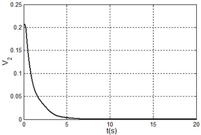
The simulation results are shown in Fig. 2-4, where the position unit and angle unit respectively are meter and radian to calculate the . The Fig. 2 is obtained under the initial state i.e. , Fig. 3 is obtained under the initial state i.e. and Fig. 4 are obtained under the initial state i.e. .
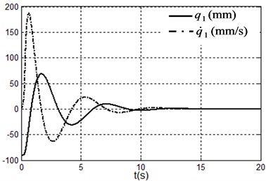
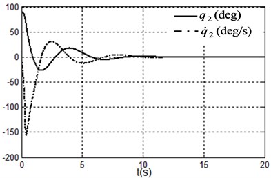
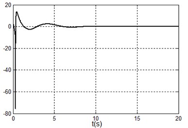
Fig. 2Simulation results under system state q1,q˙1,q2,q˙2=(100,0,0,0) i.e. x1,x˙1,x2,x˙2=(100,0,0,0)
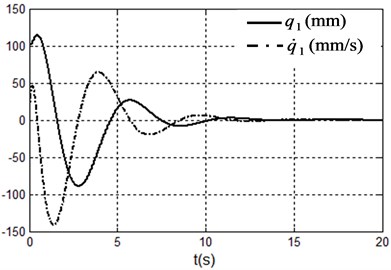
a) Position and velocity of the cart
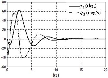
b) Angle and angle velocity of the pendulum
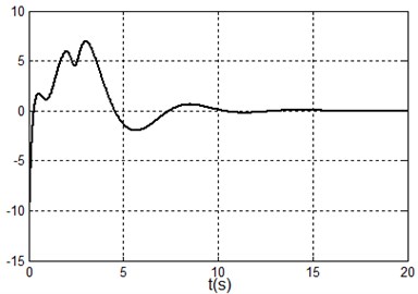
c) Control torque
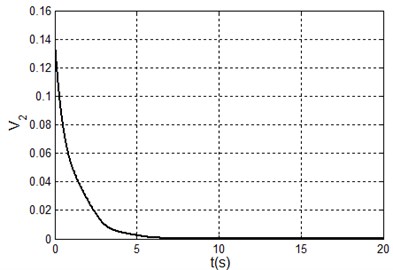
d) The Lyapunov function
It can be seen form the simulation results that the TORA system is asymptotically stable under any initial states with the proposed control algorithm. At the same time, it is shown that it is possible to suppress the translational vibration with a rotational actuation. On the other hand, the control performance can be improved through adjusting the parameters of the proposed controller.
From Fig. 3(d), the Lyapunov function is not a monotonically decreasing function. The reason is the controller switches between the nonlinear controller (14) and the linear controller (16). When the linear controller is in use, the Lyapunov function may be not a monotonically decreasing function. Lots of simulation experiments show that the parameters , , , respectively correspond to the system states , , , therefore it is easy to adjust the parameters for a improved system performance.
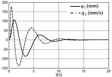
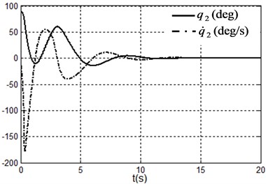
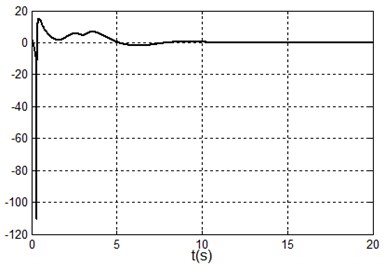
Fig. 3Simulation results under system state q1,q˙1,q2,q˙2=(–90.9,90°,0,0) i.e. x1,x˙1,x2,x˙2=(0,0,90°,0)
a) Position and velocity of the cart
b) Angle and angle velocity of the pendulum
c) Control torque
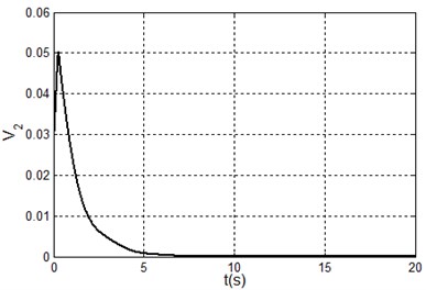
d) The Lyapunov function
Fig. 4Simulation results under system state q1,q˙1,q2,q˙2=(9.09,90°,0,0) i.e. x1,x˙1,x2,x˙2=(100,0,90°,0)
a) Position and velocity of the cart
b) Angle and angle velocity of the pendulum
c) Control torque
d) The Lyapunov function
5. Conclusions
The underactuated TORA is transformed to a nonlinear feedback cascade system with a collocated partial feedback linearization and a global change of coordinates. A nonlinear control algorithm is proposed from the backstepping technology. The design procedure treats the state variables as virtual control inputs to design the virtual controllers step by step. The first step is designed for a one-input and two-state system, the second step is designed for a one-input and one-state system, and the third step is to obtain the nonlinear controller. The system stability and the control performance are proved via the Lyapunov stability theorem or simulation results.
References
-
Robert T. B., Bernstein D. S., Coppola V. T. A benchmark problem for nonlinear control design. International Journal of Robust and Nonlinear Control, Vol. 8, Issue 4-5, 1998, p. 307-310.
-
Hung L. C., Lin H. P., Chung H. Y. Design of self-tuning fuzzy sliding mode control for TORA system. Expert Systems with Applications, Vol. 32, Issue 1, 2007, p. 201-212.
-
Li C. D., Yi J. Q., Zhao D. B. Control of the TORA system using SIRMs based type-2 fuzzy logic. Proceedings of IEEE International Conference on Fuzzy System, 2009, p. 694-699.
-
Lee C. H., Yu T. M., Chien J. C. Adaptive neural network controller design for a class of nonlinear systems using SPSA algorithm. Proceedings of the International Multi Conference on Engineers and Computer Scientists, Vol. 2, 2011, p. 967-974.
-
Avis J. M., Nersesov S. G., Nathanb R., et al. A comparison study of nonlinear control techniques for the RTAC system. Nonlinear Analysis: Real World Applications, Vol. 11, Issue 4, 2010, p. 2647-2658.
-
Jankovic M., Fontaine D., Kokotovic P. V. TORA example: cascade and passivity based control designs. IEEE Trans. Control Syst. Technol., Vol. 4, Issue 3, 1996, p. 292-297.
-
Gao B. T., Zhang X. H., Chen H. J., et al. Energy-based control design of an underactuated 2-dimensional TORA system. Proceeding of IROS'09 Proceedings of the 2009 IEEE/RSJ International Conference on Intelligent Robots and Systems, 2009, p. 1296-1301.
-
Bupp R., Bernstein D. S., Coppola V. T. Experimental implementation of integrator backstepping and passive nonlinear controllers on the RTAC testbed. International Journal of Robust and Nonlinear Control, Vol. 8, Issue 4-5, 1998, p. 435-457.
-
Wang Y. Q., Li S., Chen Q. W. A Recursive design method of controller for the stabilization of the translational oscillator with a rotational actuator system. Proceedings of the 2011 IEEE International Conference on Computer Science and Automation Engineering, Shanghai, USA, p. 558-561.
-
Chen Y. F., Huang A. C. Controller design for a class of underactuated mechanical systems. IET Control Theory Application, Vol. 6, Issue 1, 2012, p. 103-110.
-
Celani F. Output regulation for the TORA benchmark via rotational position feedback. Automatica, Vol. 47, Issue 3, 2011, p. 584-590.
-
Spong M. W. Underactuated mechanical systems. Control Problems in Robotics and Automation, Springer Verlag, London, UK, 1997.
-
Olfati-Saber R. Normal forms for underactuated mechanical systems with symmetry. IEEE Transactions on Atomatic Control, Vol. 47, Issue 2, 2002, p. 305-308.
-
Khalil H. K. Nonlinear systems. 3rd Edition. Prentise Hall, USA, 2002.
-
Katsuhiko Ogata Modern control engineering. Prentice Hall, 2009.
-
Olfati-Saber R. Nonlinear control of underactuated mechanical systems with application to robotics and aerospace vehicles. Ph. D. thesis, Massachusetts Institute of Technology, 2001.
About this article
This work is supported by the National Natural Science Foundation of China (No. 61175086) and a Project of Shandong Province Higher Educational Science and Technology Program (No. J13LN25).
