Abstract
In order to obtain the vibration response characteristics of the engine mount, its constrained modal analysis was completed based on the finite element method. The mesh of the contact part between the bolt head and the bracket part was considered as shared node, achieving the simulation of compressive contact between the bolt and bracket parts. The simulation results of natural frequencies and modal shape were verified through constrained modal experiments. The results indicated that the accuracy of the simulation results is high, and the maximum deviation between the natural frequency and the experimental value is less than 5 %. Compared to higher-order modes, the preload had a more significant impact on lower order modes. Based on the modal analysis results, reasonable excitation vibration directions were set, and the dynamic stiffness of the model was simulated and tested within the frequency range of 2400 Hz, providing important basis for optimizing vibration isolation performance.
Highlights
- The mesh of the contact part between the bolt head and the bracket part was considered as shared node, achieving the simulation of compressive contact between the bolt and bracket parts.
- Based on the modal analysis results, reasonable excitation vibration directions were set, and the dynamic stiffness of the model was simulated and tested.
- In order to obtain the vibration response characteristics of the engine mount, its constrained modal analysis was completed based on the finite element method.
1. Introduction
The automotive engine mount is an important component responsible for connecting the powertrain to the frame. The vibration transmission characteristics directly determine the residual energy generated by the powertrain, which can ultimately act on the frame. The more residual vibration energy, the greater the negative impact on vehicle comfort and NVH performance [1, 2]. For a series system, the stiffness of the suspension system can only be the stiffness of the rubber isolator when the engine mount stiffness is large enough. Once the stiffness of the bracket part is insufficient, it not only reduces the stiffness of the suspension system and reduces the isolation effect, but also causes local resonance and worsens NVH performance. With the development of computer computing power and software technology, finite element analysis technology has become a reliable main method for studying the dynamic performance of mechanical structures [3, 4]. In the early development of engine mounts, it includes structural design, performance simulation, and component level testing of the mounts. The results of modal simulation will directly demonstrate the quality of structural design, determine the final plan of structural design, and have significance for modifying and optimizing structural design.
2. Finite element analysis and test of constrained modal
2.1. Finite element modeling
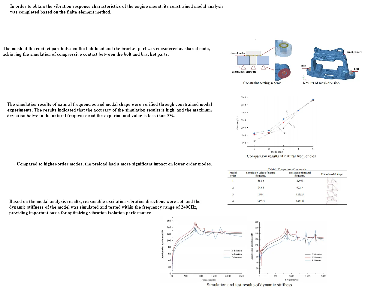
The finite element method has been widely applied in engineering analysis, and the modal analysis of continuum structures is often achieved through the finite element method. According to the principle of analytical modal analysis, the finite element method obtains the natural frequency by solving the determinant of a large matrix. HyperWorks was adopted for finite element analysis of engine mounts, which mainly includes preprocessing, solving, and post-processing. In the preprocessing work, the basic process of finite element modeling in modal analysis includes importing geometric models, geometric cleaning, establishing mesh models, assigning material properties, defining loading and boundaries, and setting control cards. After importing geometric models in Hypermesh, geometric cleaning is required, which is the key to obtaining high-quality meshes. Geometric cleaning requires repairing discontinuous and missing surfaces on the surface and removing duplicate faces. Based on engineering experience, clean up areas that may generate deformation grids, remove unnecessary feature lines, and clean up local complex geometric features that do not affect the overall calculation results. Low quality deformed meshes can easily lead to simulation results that do not match reality, and even result in simulation calculations failing. The modeling method of bolts in finite element software adopts solid modeling. To improve modeling efficiency, the local geometric features of the bolt head are ignored and the bolt head is simplified as a cylinder. The mesh of the contact part between the bolt head and the bracket part will be treated as a common node to simulate the compressive contact between the bolt head and the bracket part. The suspension bracket is fixed to the fixture base by bolts, and the material of the fixture base is cast iron. Compared to the aluminum alloy suspension bracket, the stiffness is very high. In traditional finite element modeling processes, the fixture is usually simplified to the ground. The constraint boundary fixed by bolts is simulated by constraining the bottom 6 degrees of freedom of the suspension bracket. At the same time, in engineering, the stiffness characteristics of the bolt joint are often simplified, and the connection surface between the bracket and the fixed end is directly set as a fixed constraint, as shown in Fig. 1. The finite element model after completing the preprocessing work is shown in Fig. 2, which includes 224987 second-order tetrahedral elements.
Fig. 1Constraint setting scheme
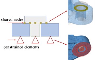
Fig. 2Results of mesh division
3. Analysis of simulation results
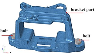
The pre processed finite element model file can be submitted to the finite element solver for calculation. Optistruct was selected as the solver for the modal analysis model, which is suitable for applications such as static and dynamic, linear and nonlinear analysis. The finite element simulation results of modal analysis under constraint state are shown in Fig. 3, where the gray area represents the position of the bracket in the stationary state, and the colored area represents the position of the bracket in the vibration state. It can be seen that at lower resonance frequencies, the maximum amplitude is distributed at the end of the model.The structure of the base position is relatively stable and can be reinforced from the edge position to achieve optimization of stiffness.
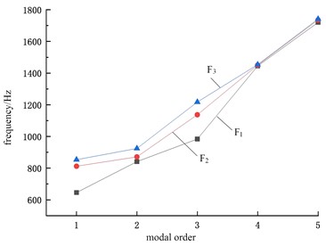
The bolt holes of the bracket have no threads, and the bolts are fastened to the fixture through threaded connections. The bracket is compressed onto the fixture by the pre tightening force of the bolts. For mechanical joints connected by bolts, the area that produces contact characteristics is generally localized near the bolt hole, indicating that the influence of the bolt joint is regional. Under different bolt preload loads, the comparison results of natural frequencies can be shown as in Fig. 4, where F1 < F2 < F3. It can be seen that the natural frequencies of modes under different preloads vary significantly under lower order modal analysis conditions, while there is almost no difference in higher order modes.
Fig. 3Modal shape diagram
a) First order vibration mode
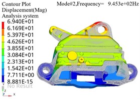
b) Second order vibration mode
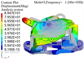
c) Third order vibration mode
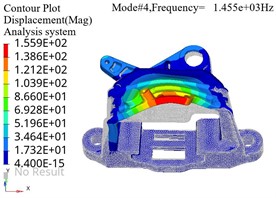
d) Fourth order vibration mode
Fig. 4Comparison results of natural frequencies
4. Testing of modal characteristics
The results of modal testing, namely modal parameters, are important indicators for evaluating the dynamic characteristics of structures [5]. They can also provide meaningful information for noise tracing. In addition, they are of great significance for dynamic modification of structures, product optimization design, and finite element model validation. In engineering, the measurement frequency response function (FRF) is often used to obtain modal parameters. There are hammer method and exciter method for measuring FRF. The purpose of modal testing for suspended supports is to obtain the modal parameters of the support under constraint conditions, namely natural frequency and modal shape. Natural frequency is used to measure the dynamic characteristics of the support, and modal shape is used to match the vibration mode of the finite element calculation results. Only the natural frequency corresponding to the consistent vibration mode has benchmarking significance. The constraint state in the modal test is shown in Fig.5. It can be seen that the part is fixed to the base fixture through bolts, and then the fixture is fixed to the ground. Using the base as a reference point, seven acceleration sensors are used for vibration mode measurement. When arranging sensors, it is necessary to maintain consistency in all directions. Based on the calculated natural frequency data of the first six modes, the experimental bandwidth is set within the range of 2400 Hz.
By external excitation, the corresponding vibration mode can be obtained in the LMS Test.Lab software. The first four natural frequencies and vibration modes were obtained in this experiment, and the test results are summarized in Table 1. In the vibration mode information, the gray wireframe part represents the initial static state of the structure, and the red wireframe part represents the position state of the structure during vibration. It can be seen that the accuracy of the simulation results is high, and the maximum deviation between the natural frequency and the experimental value is less than 5 %. For modal analysis, material parameters mainly include the elastic modulus, Poisson's ratio, and density of the material. In engineering applications, the material parameters of structures are generally obtained from raw material suppliers. However, there may be some processing processing between the raw materials and the specific product structure, resulting in changes in material attribute parameters and uncertainty in the material parameters of the final product. Therefore, it is necessary to modify the material parameters. Boundary stiffness is the contact property between the system and the outside world. When establishing a high-precision finite element model, the contact stiffness property of the boundary cannot be ignored. In traditional finite element modeling, the constraint boundary model is often simplified, ignoring the contact stiffness of the bolt joint, resulting in inconsistent simulation and experimental results. Therefore, modifying the constrained boundary model to obtain accurate boundary contact stiffness is necessary to improve the prediction accuracy of the finite element model.
Fig. 5Test for constrained modal
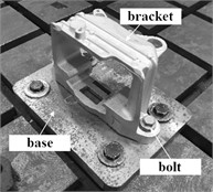
a) Constrained structure
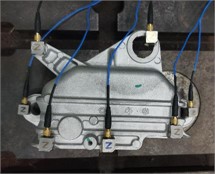
b) Layout of measuring points
Table 1Comparison of test results
Modal order | Simulation value of natural frequency | Test value of natural frequency | Test of modal shape |
1 | 858.5 | 829.6 |  |
2 | 945.3 | 922.7 |  |
3 | 1240.1 | 1225.5 |  |
4 | 1455.3 | 1431.8 |  |
5. Simulation and analysis of dynamic stiffness
5.1. Finite element modeling for dynamic stiffness analysis
In engineering, dynamic stiffness can be further divided into source point dynamic stiffness and cross point dynamic stiffness. The source point dynamic stiffness refers to the ratio of excitation force to displacement in the same position and direction. Cross point dynamic stiffness refers to the ratio of excitation force to displacement at different positions and in the same direction, and also is the stiffness of the transmission path. Due to the fact that in actual source point dynamic stiffness testing, it is impossible to achieve the situation where the excitation point and response point are completely the same, i.e. the excitation device cannot excite the sensor, there is inevitably a systematic error in source point dynamic stiffness testing. For the analysis of engine mounts, it is more reasonable to use cross point dynamic stiffness for analysis. Modal frequency response analysis will first perform modal calculations, and then use the modal deformation of the structure to reduce the number of equations and decouple the motion equations. The results of modal frequency response analysis can include displacement response, velocity response, and acceleration response. So the finite element model for modal analysis after modification can serve as the basis for dynamic stiffness analysis models.
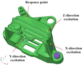
The response point is the installation position of the acceleration sensor, and the location area needs to be sufficiently flat to facilitate the installation of the sensor. In addition, the response point should also avoid the modal node area, as it is difficult to excite the modal nodes, resulting in difficulty in collecting response data. The output of the response point is set to the acceleration in the , , and directions, as shown in Fig. 6. The excitation point is the position where pulse excitation is applied. Considering the impact of the force hammer, the position plane of the excitation point should not only be flat and smooth, but also perpendicular to the direction of the excitation force, so as to maximize the vertical impact of the force hammer and reduce the impact of lateral force on the test results. Apply unit loads in corresponding directions, with a frequency range of 0-2500 Hz, including the range of the first four natural frequencies.
Fig. 6Model for dynamic stiffness analysis
5.2. Result analysis
Regarding the evaluation methods of dynamic stiffness, two methods are commonly used in engineering: the frequency response function of the ratio of acceleration to force (acceleration admittance) and the ratio of dynamic load to dynamic displacement. The evaluation methods are mostly selected based on the test results of the testing instruments. Acceleration sensors are often used for dynamic stiffness testing, so the dynamic stiffness of the bracket is evaluated using acceleration admittance. The simulation calculation results and test results of dynamic stiffness are shown in Fig. 7, which can serve as an important basis for evaluating the isolation effect of the bracket under different engine speed conditions.
Fig. 7Simulation and test results of dynamic stiffness
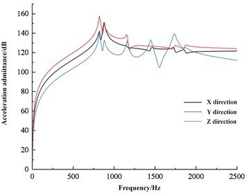
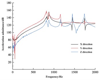
Dynamic stiffness is a measure of the ability of a structure to resist deformation under dynamic loads. Relatively speaking, in the field of NVH, the probability of a structure or material being subjected to dynamic loads is much greater than that of static loads, so dynamic stiffness is generally more concerned. In the field of vibration control engineering, precise modeling of structures requires not only high accuracy in the stiffness and mass matrix of the structure, but also considerable accuracy in the damping characteristics within a certain frequency range. For general linear structures, viscous damping or structural damping are often used. Structural damping is mainly caused by the internal friction of partially elastic structural materials and the friction between the contact surfaces of the connecting parts. For automotive structures, structural damping systems are usually used. For the vibration isolation effect of the bracket, it is required to have a higher stiffness at low frequencies, and a lower stiffness at high frequencies is better. The engine bracket must withstand the gravity of the powertrain and the torque generated by the engine, therefore its stiffness must be sufficient. When the low-frequency large displacement impact transmitted by the road surface acts on the support, sufficient stiffness is required to avoid the powertrain from generating large displacement and colliding with other components. Afterwards, during high-frequency small displacement, the bracket should provide smaller stiffness.
6. Conclusions
As an important means of studying the performance of mechanical structures, finite element digital simulation technology has received widespread attention and experienced rapid development. At present, the technical solution of using finite element technology to analyze and guide the design of structures has been widely and recognized in the engineering community. With the improvement of computer computing power and the popularization of professional software, finite element analysis technology has become an equally important scientific research tool as theoretical research and experimental analysis. Based on computer simulation technology, the modal characteristics of the engine support were studied in the paper and the following conclusions were drawn.
1) Through constrained modal experiments, it can be seen that finite element based prestressed modal simulation has high computational accuracy and can provide important basis for stiffness optimization. In addition, the results indicate that the preload has a significant impact on lower order modes, while it has almost no effect on higher order modes.
2) Based on the results of constrained modal analysis, dynamic stiffness simulation has been completed, providing important basis for vibration reduction optimization under dynamic conditions.
References
-
F. Cavaliere, S. Zlotnik, R. Sevilla, X. Larrayoz, and P. Díez, “Nonintrusive parametric NVH study of a vehicle body structure,” Mechanics Based Design of Structures and Machines, Vol. 51, No. 11, pp. 6557–6582, Nov. 2023, https://doi.org/10.1080/15397734.2022.2098140
-
B. Huang, “NVH analysis and optimization of construction hoist drive system,” Energies, Vol. 16, No. 17, pp. 102–112, 2023, https://doi.org/10.1080/10.3390/en16176199
-
G. M. Gonzalez, J. R. M. de Sousa, and L. V. S. Sagrilo, “A modal finite element approach to predict the lateral buckling failure of the tensile armors in flexible pipes,” Marine Structures, Vol. 67, No. 1, p. 102628, Sep. 2019, https://doi.org/10.1016/j.marstruc.2019.05.006
-
J. Müller, G. Jacobs, M. Ramm, S. Wischmann, P. Jagla, and J. Berroth, “Model-based NVH optimization of a tractor drivetrain during different phases of a design adaption,” Forschung im Ingenieurwesen, Vol. 87, No. 1, pp. 363–373, Mar. 2023, https://doi.org/10.1007/s10010-023-00632-3
-
Z. Feng, H. Ma, and M. J. Zuo, “Vibration signal models for fault diagnosis of planet bearings,” Journal of Sound and Vibration, Vol. 370, No. 1, pp. 372–393, May 2016, https://doi.org/10.1016/j.jsv.2016.01.041
About this article

The authors have not disclosed any funding.
The datasets generated during and/or analyzed during the current study are available from the corresponding author on reasonable request.
The authors declare that they have no conflict of interest.
