Abstract
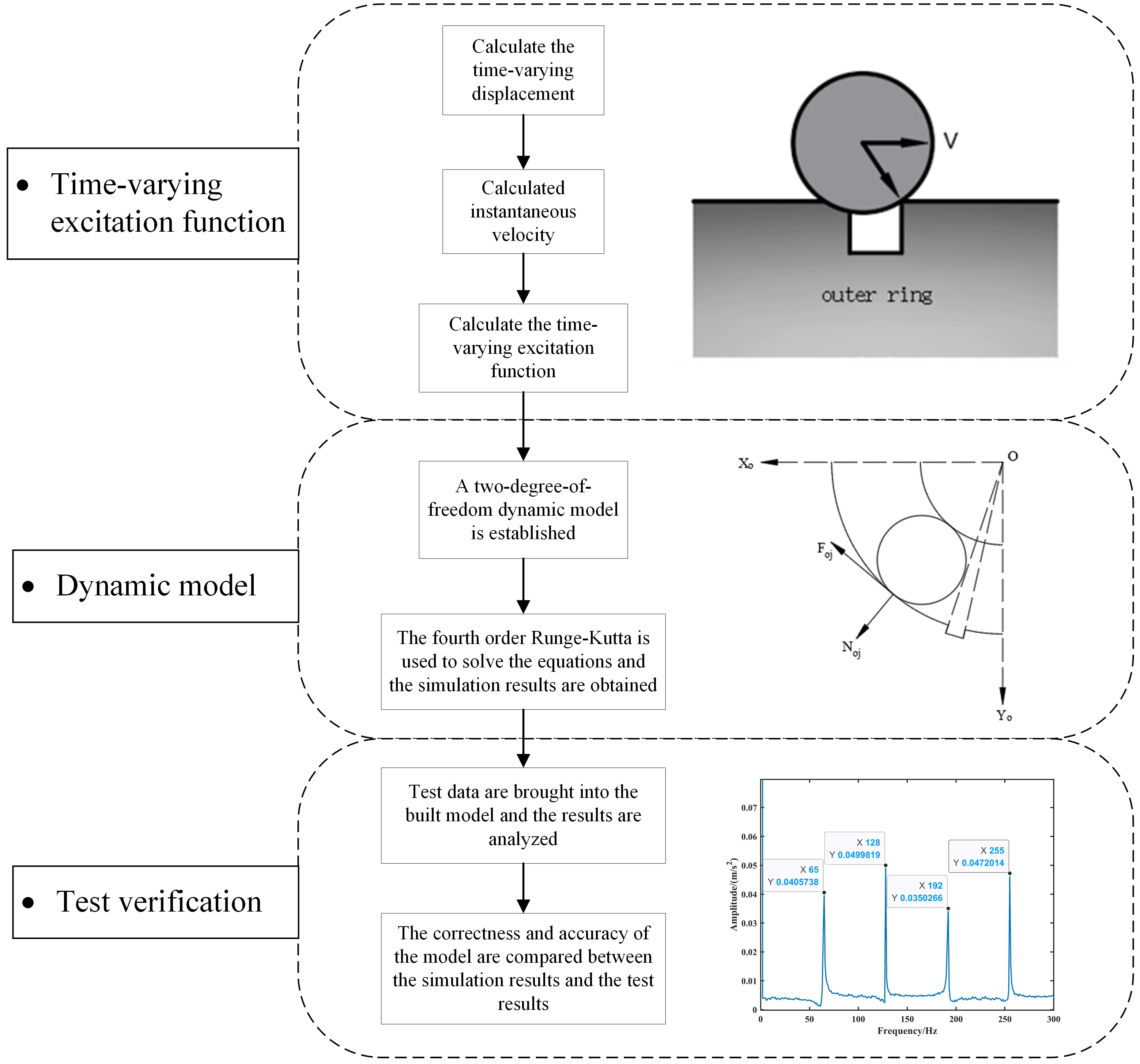
Fault mechanism analysis is one of the methods in fault diagnosis, and the dynamic modeling of rolling bearing faults plays a crucial role in studying fault mechanisms. Existing dynamic fault models only consider the impact of fault size and bearing speed on the impact force, providing an incomplete description of the impact force. In order to more accurately describe the dynamic fault model of impact forces, this paper focuses on the deep groove ball bearing with outer race faults. Factors such as defect deformation, speed, and fault size are considered, and an instantaneous impact force excitation function is proposed. Based on this proposed excitation function, a dynamic model for the outer race fault of deep groove ball bearings is established. Finally, through simulation and experimental comparison, the results indicate that the fault characteristic frequencies and their harmonics of the model in this paper are closer to the actual fault characteristic frequencies, reducing the error by 1 to 2 Hz. Therefore, the model proposed in this paper is more effective and accurate, providing a more precise rolling bearing fault model for the study of fault mechanisms.
Highlights
- The contact deformation of the fault is considered.
- The time-varying excitation function considering defect deformation is derived.
- A dynamic model of time-varying excitation function considering defect deformation is established.
- A more accurate failure mechanism model of deep groove ball bearing outer ring is established.
- The nonlinear factor of defect deformation in fault diagnosis of deep groove ball bearing is analyzed.
1. Introduction
Rolling bearings play a vital role in a series of rotating machinery, including wind turbines, aerospace, transportation, and tunnel boring machines. When faults occur in the bearing raceway, phenomena such as sliding and skidding become more severe, leading to bearing failure. To study the skidding characteristics, Gao [1-5] proposed multiple dynamic models and evaluation criteria. Statistics show that 30 % of rotating machinery faults [6] and 44 % of large asynchronous motor faults [7] are caused by faulty bearings, with about 90 % of bearing faults being localized defects in the raceway [7]. However, in the field of fault diagnosis, feature selection and data mining techniques in directions such as deep learning and signal processing [8, 9] often accompany the establishment and development of fault mechanism models. Therefore, establishing a dynamic model that better reflects the actual fault state is crucial for studying bearing fault diagnosis.
In previous fault mechanism studies, many scholars characterized the vibration characteristics of bearings by establishing local fault dynamic models. McFadden and Smith [10, 11], for example, integrated the effects of bearing geometry, speed, load distribution, transfer functions, and vibration decay to establish a vibration model for single-point and multi-point defects in the inner race of rolling bearings under constant radial load. Patil [12], using Hertzian contact deformation theory, proposed an analytical model predicting the impact of local defects on the vibration of ball bearings. Cao [13] established a dynamic model for the vibration mechanism of local defects in cylindrical roller bearings. Niu [14] studied the vibration response of defects in the outer race of cylindrical roller bearings and established a dynamic model for cylindrical roller bearings with roller defects. Tu [15, 16], considering sliding and modifying the deformation coefficient of non-ideal Hertz contact, proposed vibration response dynamic models for cylindrical roller bearings. Xu [17], using a mixed lubrication model, explored the frictional vibration mechanism under rough sliding-rolling contact. Most of the above models did not describe the impact of fault excitation on the model or simplified the fault excitation into a single-pulse process.
In recent years, researchers have divided the rolling element through the defect area into three stages: entering the pre-fault edge, impacting the post-fault edge, and leaving the post-fault edge. Impact force has gradually become an important factor in vibration characteristic models. Behzad [18] assumed that random vibration excitation sources are generated by metal contact between bearing units during the rolling process, proposing a new model for the generation of rolling bearing vibration. Khanam [19] proposed a method for identifying local bearing faults based on impact force evaluation, structural response analysis, and experiments. Liu [20, 21], based on the Greenwood and Williamson method, established a time-varying stiffness excitation model for cylindrical roller bearings with local rough surface defects, creating a dynamic model for cylindrical roller bearings with time-varying stiffness excitation. However, these models did not characterize the impact force excitation function.
As research progressed, scholars found that when the rolling element enters the pre-fault edge, impact force is also generated. Therefore, scholars referred to the phenomenon of rolling elements colliding with the pre- and post-fault edges as the “double impact” phenomenon. Luo [22, 23], for example, established a dynamic model for the double impact phenomenon of the outer race peeling of ball bearings, but the model did not consider the influence of bearing speed on the impact force. Li [24] and Zhang [25], using different methods based on time-varying displacement excitation functions, comprehensively considered defect size and speed, proposing time-varying impact force excitation functions for defective rolling elements. Unfortunately, the calculation of this function did not consider the influence of defect deformation, meaning that the motion of the rolling element on the raceway was treated as rigid body motion, inevitably leading to an inaccurate description of the time-varying excitation function and fault model under actual conditions.
From the above analysis, it is evident that scholars have made long-term developments in the study of fault models. However, in these studies, fault excitation has been simplified to a single pulse, or the motion of the rolling element has been simplified to rigid body motion, both of which fail to accurately represent the actual contact process of the rolling element through the defect. To address this issue, this paper, based on existing time-varying excitation fault models, considers the influence of contact deformation, further calculates the time-varying impact force excitation function, achieving more accurate results. On this basis, this paper establishes a dynamic model for the outer race fault of rolling bearings, considering time-varying excitation with contact deformation, to more comprehensively reflect the contact state of the rolling element through the faulty area. Experimental results show that this fault dynamic model is closer to the actual situation.
2. The principle of impact force variation caused by contact deformation
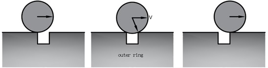
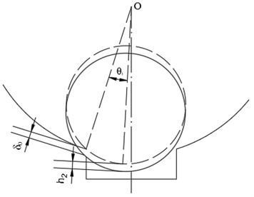
The rolling element generates instantaneous impact force when passing through the defect area, and it has become common not to consider contact deformation when calculating the impact force. However, in actual working conditions, the contact between the rolling element and the cage and the outer ring will cause bearing deformation [26]. Whether it is a cage fault [27] or an outer ring fault [28], when the rolling element passes through the defect, the impact force will change due to contact deformation. The variation in impact force caused by contact deformation can be illustrated using Fig. 1: Assuming the outer race of the bearing remains stationary, the inner race rotates at a constant speed, and the bearing is subjected to a radial load. When a rolling element enters the defective region, it undergoes contact deformation with the starting point of the fault. Until the rolling element reaches the end of the fault region, there will be no contact deformation at the fault ending position. Hence, there is a height difference between the fault starting and ending positions, representing the magnitude of contact deformation. As the rolling element moves to the fault ending position, a comparison with the case without considering contact deformation, as shown in Fig. 2, reveals a certain variation in the impact force. Afterward, the rolling element undergoes contact deformation with the fault ending position until it leaves the defective region.
Fig. 1The schematic diagram of impact force under contact deformation
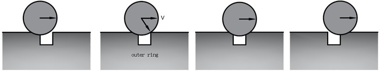
Fig. 2The schematic diagram of impact force in the ideal state
3. Time-varying excitation model
When a rolling bearing experiences an outer race defect and the rolling elements enter the faulty region of the raceway, the rolling elements come into contact with the edges of the local fault, causing deviations in their motion trajectories. This phenomenon is referred to as displacement excitation. However, when the rolling elements make contact with the fault edges, an instantaneous impact force is generated. The magnitude of this force is not only influenced by the fault size and bearing rotational speed but also by the contact deformation between the rolling elements and the outer race. Therefore, focusing on the outer race defect of rolling bearings, a time-varying excitation model is established that considers both the fault size and bearing rotational speed, as well as the contact deformation.
3.1. Calculation of time-varying displacement excitation function
Displacement excitation is caused by the sudden change in contact gap resulting from the contact between the rolling element and the edge of the local defect. Compared to the ideal model, the time-varying displacement can be divided into two parts for consideration: one part is caused by the outer race defect, and the other part is caused by the contact deformation between the rolling element and the outer race. The time-varying displacement caused by the outer race defect is denoted as , while the time-varying displacement caused by contact deformation is denoted as . The overall time-varying displacement is denoted as . Eq. (1) defines the entire time-varying displacement:
3.1.1. Time varying displacement caused by defects in the outer ring
Fig. 3 shows the instantaneous displacement generated when the rolling element enters the defect position. is the center of the outer ring. is the center of the rolling element. is the distance from the center of the outer ring to the outer ring raceway. is the radius of the rolling element. indicates the Angle of the fault area. is the Angle that the rolling element passes from the fault origin position. Eq. (2) defines the geometric relationship of :
Eq. (3) defines the time-varying displacement caused by the outer race defect:
Fig. 3The dimensional relationship of the rolling element into the defect
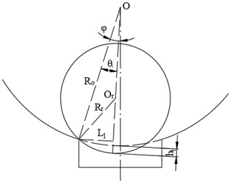
Fig. 4The contact deformation diagram between the rolling element and the outer ring
3.1.2. Time varying displacement caused by contact deformation of the outer ring
The rolling element generates contact deformation whether or not it enters the fault area. However, when the rolling element is not in the defective area, this contact deformation does not result in an impact force. When a rolling element enters the fault region but has not reached the end of the defect, contact deformation occurs at the defect's starting position. However, there is no contact deformation at the defect's ending position. Therefore, when the rolling element contacts the defect’s ending position, it results in instantaneous displacement excitation due to the height difference caused by contact deformation. Since the stiffness of the rolling element is greater than that of the outer ring, only contact deformation on the outer ring raceway is considered. It is assumed that the deformation occurs in the direction from the center of the outer ring to the defect's starting position, and the contact deformation between the rolling element and the outer ring is represented as . Fig. 4 shows the instantaneous displacement excitation caused by the height difference resulting from the contact deformation when the rolling element contacts the fault region and reaches the end position of the defect.
According to the Hertz contact theory, Eq. (4) defines the contact deformation between the rolling element and the outer ring. represents the contact displacement of dimension 1 between the rolling element and the outer ring. is the load component of the bearing in the -axis direction. is the curvature and function of the rolling element:
Eq. (5) defines the curvature and function of the rolling element. is the diameter of the rolling element. , , is the bearing pressure Angle. is the pitch circle diameter:
Eq. (6) defines the time-varying displacement caused by contact deformation:
Therefore, Eq. (7) defines the time-varying displacement excitation function as the rolling element passes through the faulty region:
When the rolling element passes through a non-fault region, although contact deformation occurs, this contact deformation does not generate instantaneous impact forces, meaning there is no instantaneous displacement excitation. To sum up, Eq. (8) defines the displacement excitation function of the rolling element:
3.2. Calculation of radial instantaneous velocity
The calculation of instantaneous impact force can be obtained using the impulse theorem. However, to determine the instantaneous impact force, you first need to calculate the radial instantaneous velocity of the rolling element when it experiences an impact while passing through the fault zone. The radial instantaneous velocity can be obtained by taking the first derivative of the time-varying displacement excitation function with respect to time. Eq. (9) defines the instantaneous radial velocity:
3.3. Calculation of instantaneous impact force
Eq. (10) defines the application of the impulse theorem to the rolling element as it moves from the starting position of the defect to the ending position of the defect in the radial direction. is the impact force. is the time for the rolling element to pass through the fault area. is the mass of the rolling element. is the Angle between the impact force and the radial direction:
Fig. 5 shows the positional relationship between the rolling element and the ending position of the defect after the impact occurs. Eqs. (11), (12) and (13) define the geometric relationships of and . In addition, is the fault size:
Eq. (14) defines the time that the rolling element spends passing through the defect region:
Eq. (15) defines the expression for calculating the impact force:
Eqs. (16) and (17) define the geometric relationship of during the time when the impact force is acting:
Fig. 5The schematic diagram of collision between rolling element and defect
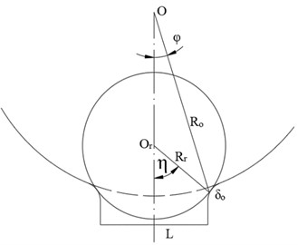
Fig. 6The outer ring defect contact model diagram
Therefore, the impact force can be further calculated. Eq. (18) defines the expression for the impact force. is the cage angular velocity. is the inner angular velocity:
Eq. (19) defines the expression for the inner angular velocity. is the inner ring speed:
Eq. (20) defines the expression for the cage angular velocity:
4. Dynamic equation of bearing outer ring defect
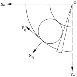
Based on the bearing geometry, Fig. 6 shows a schematic diagram of a rolling bearing with an outer ring defect. is the bearing geometric coordinate system. The generation of instantaneous impact force only occurs when the rolling element makes contact with the defect’s ending position as it enters the fault region. Additionally, the magnitude of the impact force is related to the defect size, inner ring rotation speed and contact deformation. Eq. (21) defines the dynamic equation for the -direction and -direction of the outer ring defect. represents the angular position of the -th rolling element at time . represents the angle that the -th rolling element traverses through the defect region. is the total mass of the rolling element and the inner ring. represents the contact force between the -th rolling element and the outer ring, while represents the frictional force between them. represents the impact force acting on the -th rolling element:
Eq. (22) defines the expression for the impact force acting on the -th rolling element:
Eq. (23) defines the expression for the angular position of the -th rolling element at time . is the number of scrolling elements. represents the angular position of the first rolling element relative to the positive -axis direction at time zero. Furthermore, represents the contact deformation between the -th rolling element and the outer ring:
Eq. (24) defines the expression for the contact deformation between the -th rolling element and the outer ring. is radial clearance:
According to the Hertz contact theory, Eq. (25) defines the expression for the contact force between the -th rolling element and the outer ring. represents the contact coefficient between the rolling element and the outer ring. represents the contact stiffness between the rolling element and the outer ring:
Therefore, Eq. (26) defines the expression for the frictional force between the -th rolling element and the outer ring. represents the dynamic friction factor between the rolling element and the outer ring:
Finally, this paper focuses on the study of a 6205 bearing and determines certain parameters. 0.1, 1.5, 0.1. According to the Eq. (5), 0.224. Eventually, can be calculated. 1.44×10⁷ N/(mm1.5).
5. Test verification analysis
In this article, a 6205 deep groove ball bearing is studied, and relevant parameters are shown in Table 1.
Table 16205 Bearing geometric parameters
Parameter name | Parameter size |
Inner ring size (mm) | 25 |
Outer ring size (mm) | 52 |
Pitch circle dimension (mm) | 38.5 |
Rolling diameter (mm) | 7.9 |
Number of rolling elements | 9 |
Radial clearance | CN |
Rolling mass (g) | 2 |
5.1. Model simulation analysis
In MATLAB, the model proposed in this paper is established and solved using the fourth-order Runge-Kutta method. This section conducts simulations with two different rotational speeds.
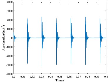
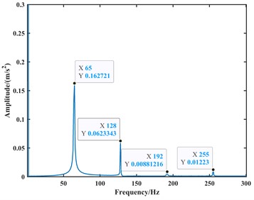
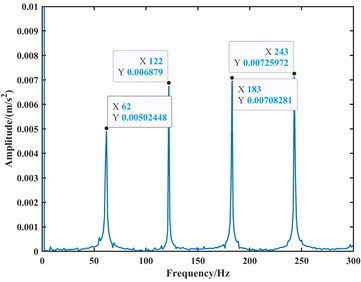
(1) The parameters are set with a rotational speed of 1000 rpm, lateral load of 0, radial load of 500 N, and a fault size of 0.2 mm. Other parameters are configured based on Table 1. According to previous theoretical studies, the characteristic frequency of outer race defect is approximately 60 Hz at a bearing speed of 1000 rpm. In this paper, the calculation step size is set to 0.00001 s, and the acceleration signal is shown in Fig. 7. The acceleration signal is subjected to Fourier transform to obtain the spectrum of the vibration signal due to the outer race fault in the bearing. The result is shown in Fig. 8.
Fig. 7The time-domain plot of the simulated acceleration signal for the bearing outer ring fault at 1000 rpm
a) The -direction
b) The -direction
(2) The parameters are set with a rotational speed of 1750 rpm, lateral load of 0, radial load of 500 N, and a fault size of 0.2 mm. Other parameters are configured based on Table 1. According to previous theoretical studies, the characteristic frequency of outer race defect is approximately 104 Hz at a bearing speed of 1000 rpm. In this paper, the calculation step size is set to 0.00001 s, and the acceleration signal is shown in Fig. 9. The acceleration signal is subjected to Fourier transform to obtain the spectrum of the vibration signal due to the outer race fault in the bearing. The result is shown in Fig. 10.
Fig. 8The envelope spectrum plot of the simulated acceleration signal for the bearing outer ring fault at 1000 rpm
a) The -direction
b) The -direction
Fig. 9The time-domain plot of the simulated acceleration signal for the bearing outer ring fault at 1750 rpm
a) The -direction
b) The -direction
Fig. 10The envelope spectrum plot of the simulated acceleration signal for the bearing outer ring fault at 1750 rpm
a) The -direction
b) The -direction
The time-domain plots of the velocity and acceleration signals reveal periodic fluctuations due to the periodic variation in contact forces between components during the operation of the ball bearing. In the frequency domain analysis, the spectrum exhibits harmonics related to the outer race fault frequency component. At a speed of 1000 rpm, the outer race fault frequency, its second harmonic, third harmonic, and fourth harmonic are approximately 65 Hz, 128 Hz, 192 Hz, and 255 Hz, respectively. At a speed of 1750 rpm, the corresponding frequencies are approximately 112 Hz, 223 Hz, 335 Hz, and 446 Hz. Due to precision issues resulting in integer data, it can be observed that the outer race fault characteristic frequency is approximately 64 Hz at a speed of 1000 rpm, and approximately 111.5 Hz at a speed of 1750 rpm through the analysis of the second harmonic, third harmonic, and fourth harmonic. Additionally, during the operation of the bearing, with a constant angular velocity of the rolling element revolution and a constant time interval between impacts on the outer race fault region, the spectrum exhibits harmonics related to the outer race fault frequency.
5.2. Experimental analysis
To further validate the correctness of the model developed in this study, experiments are conducted using a new set of rolling bearing data. This dataset is sourced from the HZXT-DS-003 double-span double-rotor rolling bearing test rig at the School of Mechanical Engineering, Inner Mongolia University of Science and Technology. Fig. 11 shows a schematic diagram of the HZXT-DS-003 rolling bearing test rig.
Fig. 11The schematic diagram of the HZXT-DS-003 rolling bearing test rig
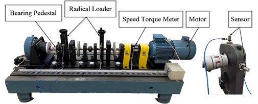
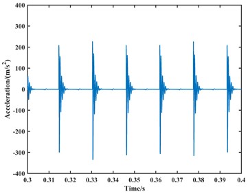
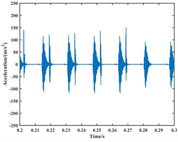
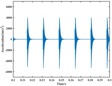
The model of the rolling bearing is 6205-2RS, and there is a single-point damage with a diameter of 0.2 mm on both the outer race and inner race raceways, created through electrical discharge machining. Bearing data is collected from the bearing housing using an acceleration sensor, with rotational speeds of the shaft set at 1000 rpm and 1750 rpm. The sampling frequency is 1.2 kHz. The results of the two experiments are subjected to time-domain and frequency-domain analyses, as shown in Figs. 12 and 13.
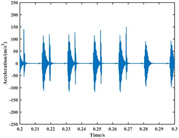
Fig. 12The plot of the vibration acceleration signal for the bearing outer ring fault at 1000 rpm
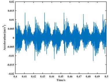
a) The time-domain plot
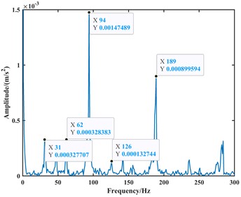
b) The envelope spectrum plot
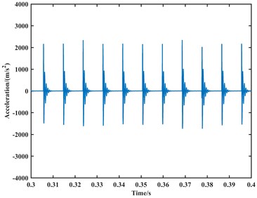
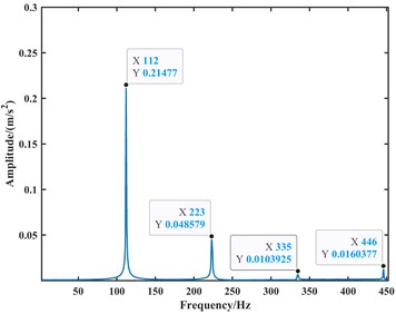
Fig. 13The plot of the vibration acceleration signal for the bearing outer ring fault at 1750 rpm
a) The time-domain plot
b) The envelope spectrum plot
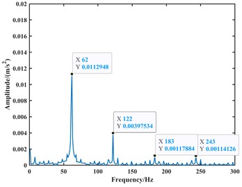
From the time-domain analysis in the above figures, the vibration acceleration signals of the two experiments are coupled with other signals. This is because the test rig inevitably introduces vibrations and noise from other components. In comparison to computer simulations, experimental results in complex test environments are inevitably influenced directly or indirectly by these factors. From the frequency-domain analysis, both inner and outer race faults are present in the frequency domain plot due to faults on the inner and outer race of the bearing. However, upon analysis, when the speed is set to 1000 rpm, the frequencies of the outer race fault, its second harmonic, and third harmonic in the frequency domain plot are approximately 62 Hz, 126 Hz, and 189 Hz, respectively. When the speed is set to 1750 rpm, the frequencies of the outer race fault, its second harmonic, and third harmonic in the frequency domain plot are approximately 110 Hz, 220 Hz, and 330 Hz, respectively. Due to precision issues resulting in integer data, it can be observed that the outer race fault characteristic frequency is approximately 63 Hz at a speed of 1000 rpm and approximately 110 Hz at a speed of 1750 rpm through the analysis of the second harmonic and third harmonic. Compared to the theoretical values, the experimental results show a slight deviation in fault characteristic frequencies due to various practical factors. However, when compared to the model proposed in this paper, the fault characteristic frequencies from the experiments are closer.
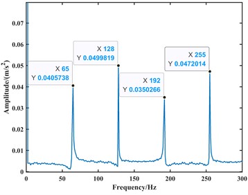
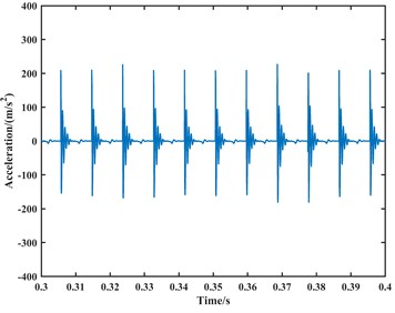
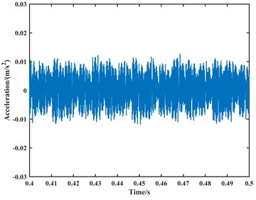
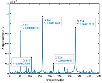
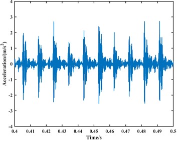
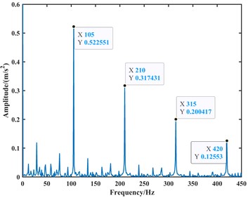
To further validate the correctness of the model and account for the influence of practical factors such as noise in the above experiments, this paper conducts another analysis using a new set of data. The data is sourced from the bearing dataset of Case Western Reserve University in the United States, with a rolling bearing model SKF6205, an outer race single-point fault diameter of 0.007 inches, a shaft rotational speed of 1750 rpm, and a data sampling frequency of 12 kHz. The time-domain and frequency-domain analyses of the data are shown in Fig. 14.
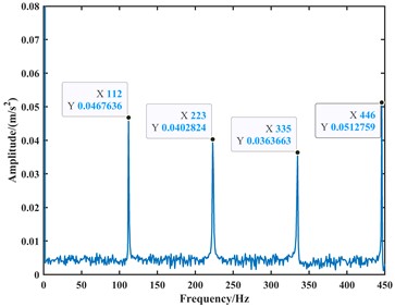
Fig. 14The plot of the vibration acceleration signal for the bearing outer ring fault at 1750 rpm
a) The time-domain plot
b) The envelope spectrum plot
From the time-domain analysis, the vibration acceleration signal is clearer compared to the experiment, but it still exhibits coupling with other signals when compared to the simulation results. This indicates that the experimental environment has some influence on the results, and the experimental results fall within the range of error. In the frequency-domain analysis, the frequencies of the outer race fault, its second harmonic, third harmonic, and fourth harmonic in the frequency domain plot are approximately 105 Hz, 210 Hz, 315 Hz, and 420 Hz, respectively. This suggests that the closer the fault characteristic frequencies are to theoretical values, the fewer influencing factors there are. Conversely, the more actual influencing factors considered, the closer the fault characteristic frequencies of the model are to the actual values. Therefore, this confirms the correctness and accuracy of the dynamic model proposed in this study.
5.3. Comparison and analysis with the existing model
In order to highlight that the dynamic model proposed in this paper is more in line with the actual fault model, this section conducts a comparative analysis with an existing model. To ensure fairness and authenticity of the results, the existing model continues to use the deep groove ball bearing 6205 as the research object. The existing model is established in MATLAB and solved using the fourth-order Runge-Kutta method. This section still sets up simulations for two different rotational speeds.
(1) The parameters are set with a rotational speed of 1000 rpm, lateral load of 0, radial load of 500 N, and a fault size of 0.2 mm. Other parameters are configured based on Table 1. The calculation step size is set to 0.00001 s, and the acceleration signal is shown in Fig. 15. The acceleration signal is subjected to Fourier transform to obtain the spectrum of the vibration signal due to the outer race fault in the bearing. The result is shown in Fig. 16.
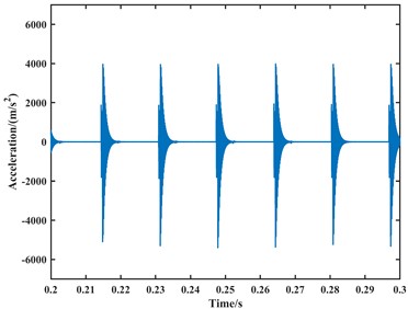
Fig. 15The existing model simulates the time-domain plot of the acceleration signal at 1000 rpm
a) The -direction
b) The -direction
Fig. 16The existing model simulates the envelope spectrum plot of the acceleration signal at 1000 rpm
a) The -direction
b) The -direction
(2) The parameters are set with a rotational speed of 1750 rpm, lateral load of 0, radial load of 500 N, and a fault size of 0.2 mm. Other parameters are configured based on Table 1. The calculation step size is set to 0.00001 s, and the acceleration signal is shown in Fig. 17. The acceleration signal is subjected to Fourier transform to obtain the spectrum of the vibration signal due to the outer race fault in the bearing. The result is shown in Fig. 18.
Fig. 17The existing model simulates the time-domain plot of the acceleration signal at 1750 rpm
a) The -direction
b) The -direction
Fig. 18The existing model simulates the envelope spectrum plot of the acceleration signal at 1750 rpm
a) The -direction
b) The -direction
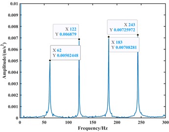
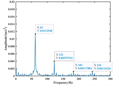
From the time-domain analysis, the acceleration signal still exhibits periodic fluctuations. In the frequency-domain analysis, harmonics related to the outer race fault frequency are observed in the spectrum. When the speed is set to 1000 rpm, the frequencies of the outer race fault, its second harmonic, third harmonic, and fourth harmonic in the frequency domain plot are approximately 62 Hz, 122 Hz, 183 Hz, and 243 Hz, respectively. When the speed is set to 1750 rpm, the frequencies of the outer race fault, its second harmonic, third harmonic, and fourth harmonic in the frequency domain plot are approximately 107 Hz, 213 Hz, 319 Hz, and 425 Hz, respectively. Due to precision issues resulting in integer data, it can be observed that the outer race fault characteristic frequency is approximately 61 Hz at a speed of 1000 rpm and approximately 106.5 Hz at a speed of 1750 rpm through the analysis of the second harmonic, third harmonic, and fourth harmonic. Compared to the model proposed in this paper, the fault characteristic frequencies from the model are closer to the actual values, with an accuracy improvement of 1 to 2 Hz. Therefore, it can be considered that the fault dynamic model proposed in this paper is correct. Finally, the analysis results are summarized in Table 2.
Table 2Summary of results
Rotational speed | Test | Fault characteristic frequency (Hz) | Compared with the test value (Hz) |
1000 rpm | Theoretical value | 59.6 | –3.4 |
Existing model | 61 | –2 | |
This research model | 64 | +1 | |
Experimental value | 63 | – | |
1750 rpm | Theoretical value | 104.3 | –5.7 |
Public data | 105 | –5 | |
Existing model | 106.5 | –3.5 | |
This research model | 111.5 | +1.5 | |
Experimental value | 110 | – |
6. Conclusions
In this study, the outer race fault of a deep groove ball bearing was investigated, and factors such as rolling element contact deformation were introduced. A dynamic model for the outer race fault of the deep groove ball bearing was established, and the validity of the model was verified. The following conclusions were drawn:
1) A new dynamic model for the vibration of rolling bearings was proposed, considering time-varying displacement excitation and instantaneous impact force under contact deformation based on the Hertz contact theory. Unlike previous studies, the time-varying displacement excitation function in this paper was established considering the contact deformation between the rolling element and the outer race raceway. Furthermore, the impact force function incorporated the influencing factors of contact deformation to accurately characterize the contact process between the rolling element and the faulty region.
2) The analysis of the simulated vibration signals from the outer race fault in rolling bearings indicates that the fault vibration model established in this paper has characteristic frequencies comparable to previous models, all within an acceptable error range. However, the fault dynamic model proposed in this paper exhibits an accuracy improvement of 1 to 2 Hz, providing a more precise prediction of one-dimensional vibration feature distributions such as fault characteristic frequencies.
Although this study calculated contact deformation using Hertz contact theory, there may be minor errors due to the non-ideal Hertz contact in real scenarios. Future research could involve the application of finite element analysis and other software to correct the contact stiffness under non-ideal Hertz contact, enabling the calculation of more accurate contact deformations and bringing the fault model closer to reality. Additionally, future studies could build upon the model proposed in this paper to establish a remaining life prediction model.
References
-
S. Gao, Q. Han, P. Pennacchi, S. Chatterton, and F. Chu, “Dynamic, thermal, and vibrational analysis of ball bearings with over-skidding behavior,” Friction, Vol. 11, No. 4, pp. 580–601, Jul. 2022, https://doi.org/10.1007/s40544-022-0622-9
-
S. Gao, S. Chatterton, L. Naldi, and P. Pennacchi, “Ball bearing skidding and over-skidding in large-scale angular contact ball bearings: Nonlinear dynamic model with thermal effects and experimental results,” Mechanical Systems and Signal Processing, Vol. 147, p. 107120, Jan. 2021, https://doi.org/10.1016/j.ymssp.2020.107120
-
S. Gao, S. Chatterton, P. Pennacchi, Q. Han, and F. Chu, “Skidding and cage whirling of angular contact ball bearings: Kinematic-hertzian contact-thermal-elasto-hydrodynamic model with thermal expansion and experimental validation,” Mechanical Systems and Signal Processing, Vol. 166, p. 108427, Mar. 2022, https://doi.org/10.1016/j.ymssp.2021.108427
-
S. Gao, Q. Han, N. Zhou, P. Pennacchi, and F. Chu, “Stability and skidding behavior of spacecraft porous oil-containing polyimide cages based on high-speed photography technology,” Tribology International, Vol. 165, p. 107294, Jan. 2022, https://doi.org/10.1016/j.triboint.2021.107294
-
S. Gao et al., “Experimental and theoretical approaches for determining cage motion dynamic characteristics of angular contact ball bearings considering whirling and overall skidding behaviors,” Mechanical Systems and Signal Processing, Vol. 168, p. 108704, Apr. 2022, https://doi.org/10.1016/j.ymssp.2021.108704
-
R. Rubini and U. Meneghetti, “Application of the envelope and wavelet transform analyses for the diagnosis of incipient faults in ball bearings,” Mechanical Systems and Signal Processing, Vol. 15, No. 2, pp. 287–302, Mar. 2001, https://doi.org/10.1006/mssp.2000.1330
-
P. Zhang, Y. Du, T. G. Habetler, and B. Lu, “A survey of condition monitoring and protection methods for medium-voltage induction motors,” IEEE Transactions on Industry Applications, Vol. 47, No. 1, pp. 34–46, Jan. 2011, https://doi.org/10.1109/tia.2010.2090839
-
M. Demetgul, K. Yildiz, S. Taskin, I. N. Tansel, and O. Yazicioglu, “Fault diagnosis on material handling system using feature selection and data mining techniques,” Measurement, Vol. 55, pp. 15–24, Sep. 2014, https://doi.org/10.1016/j.measurement.2014.04.037
-
Z. Jiang, M. Hu, K. Feng, and Y. He, “Weak fault feature extraction scheme for intershaft bearings based on linear prediction and order tracking in the rotation speed difference domain,” Applied Sciences, Vol. 7, No. 9, p. 937, Sep. 2017, https://doi.org/10.3390/app7090937
-
P. D. McFadden and J. D. Smith, “Model for the vibration produced by a single point defect in a rolling element bearing,” Journal of Sound and Vibration, Vol. 96, No. 1, pp. 69–82, Sep. 1984, https://doi.org/10.1016/0022-460x(84)90595-9
-
P. D. McFadden and J. D. Smith, “The vibration produced by multiple point defects in a rolling element bearing,” Journal of Sound and Vibration, Vol. 98, No. 2, pp. 263–273, Jan. 1985, https://doi.org/10.1016/0022-460x(85)90390-6
-
M. S. Patil, J. Mathew, P. K. Rajendrakumar, and S. Desai, “A theoretical model to predict the effect of localized defect on vibrations associated with ball bearing,” International Journal of Mechanical Sciences, Vol. 52, No. 9, pp. 1193–1201, Sep. 2010, https://doi.org/10.1016/j.ijmecsci.2010.05.005
-
H. Cao, S. Su, X. Jing, and D. Li, “Vibration mechanism analysis for cylindrical roller bearings with single/multi defects and compound faults,” Mechanical Systems and Signal Processing, Vol. 144, p. 106903, Oct. 2020, https://doi.org/10.1016/j.ymssp.2020.106903
-
L. Niu, H. Cao, H. Hou, B. Wu, Y. Lan, and X. Xiong, “Experimental observations and dynamic modeling of vibration characteristics of a cylindrical roller bearing with roller defects,” Mechanical Systems and Signal Processing, Vol. 138, p. 106553, Apr. 2020, https://doi.org/10.1016/j.ymssp.2019.106553
-
W. Tu, W. Yu, Y. Shao, and Y. Yu, “A nonlinear dynamic vibration model of cylindrical roller bearing considering skidding,” Nonlinear Dynamics, Vol. 103, No. 3, pp. 2299–2313, Feb. 2021, https://doi.org/10.1007/s11071-021-06238-0
-
W. Tu, G. Zhang, and Y. Luo, “Vibration characteristics analysis of rolling bearing based on sliding non-ideal Hertz contact,” (in Chinese), Journal of Vibration and Shock, Vol. 42, No. 5, pp. 30–8, 2023, https://doi.org/10.13465/j.cnki.jvs.2023.05.005
-
C. Xu, B. Li, and T. Wu, “Wear characterization under sliding-rolling contact using friction-induced vibration features,” Proceedings of the Institution of Mechanical Engineers, Part J: Journal of Engineering Tribology, Vol. 236, No. 4, pp. 634–647, Jul. 2021, https://doi.org/10.1177/13506501211029798
-
M. Behzad, A. R. Bastami, and D. Mba, “A new model for estimating vibrations generated in the defective rolling element bearings,” Journal of Vibration and Acoustics, Vol. 133, No. 4, pp. 041–11, Aug. 2011, https://doi.org/10.1115/1.4003595
-
S. Khanam, J. K. Dutt, and N. Tandon, “Impact force based model for bearing local fault identification,” Journal of Vibration and Acoustics, Vol. 137, No. 5, pp. 051–2, Oct. 2015, https://doi.org/10.1115/1.4029988
-
J. Liu, Z. Shi, and Y. Shao, “An analytical model to predict vibrations of a cylindrical roller bearing with a localized surface defect,” Nonlinear Dynamics, Vol. 89, No. 3, pp. 2085–2102, May 2017, https://doi.org/10.1007/s11071-017-3571-5
-
J. Liu and L. Wang, “Dynamic modelling of combination imperfects of a cylindrical roller bearing,” Engineering Failure Analysis, Vol. 135, p. 106102, May 2022, https://doi.org/10.1016/j.engfailanal.2022.106102
-
M. Luo, Y. Guo, H. Andre, X. Wu, and J. Na, “Dynamic modeling and quantitative diagnosis for dual-impulse behavior of rolling element bearing with a spall on inner race,” Mechanical Systems and Signal Processing, Vol. 158, No. 7, p. 107711, Sep. 2021, https://doi.org/10.1016/j.ymssp.2021.107711
-
M. Luo, H. André, Y. Guo, and Y. Peng, “Analysis of contact behaviours and vibrations in a defective deep groove ball bearing,” Journal of Sound and Vibration, Vol. 570, p. 118104, Feb. 2024, https://doi.org/10.1016/j.jsv.2023.118104
-
H. Li, Y. He, and K. Feng, “Dynamic modeling of rolling bearing local fault considering time-varying excitation,” (in Chinese), Acta Aeronautica et Astronautica Sinica, Vol. 43, No. 8, pp. 87–98, 2022.
-
R. Zhang, L. Guo, Z. Zong, H. Gao, M. Qian, and Z. Chen, “Dynamic modeling and analysis of rolling bearings with rolling element defect considering time-varying impact force,” Journal of Sound and Vibration, Vol. 562, p. 117820, Oct. 2023, https://doi.org/10.1016/j.jsv.2023.117820
-
M. Wang, K. Yan, X. Zhang, Y. Zhu, and J. Hong, “A comprehensive study on dynamic performance of ball bearing considering bearing deformations and ball-inner raceway separation,” Mechanical Systems and Signal Processing, Vol. 185, p. 109826, Feb. 2023, https://doi.org/10.1016/j.ymssp.2022.109826
-
T. Russell, F. Sadeghi, Y. S. Kang, and I. Mazzitelli, “The influence of cage pocket lubrication on the simulation of deep groove ball bearing cage motion,” Journal of Tribology, Vol. 146, No. 2, pp. 002–201, Feb. 2024, https://doi.org/10.1115/1.4063624
-
P. H. Jain, S. P. Bhosle, A. J. Keche, and R. G. Desavale, “A dynamic model of outer race defective bearing considering the unbalanced shaft-bearing system with experimental simulation,”, Journal of Tribology, Vol. 146, No. 1, pp. 014–301, Jan. 2024, https://doi.org/10.1115/1.4062689
About this article

The support for this research under the National Natural Science Foundation of China (No. 51965052 and 52365014), the Central Government’s Guidance in Local Science and Technology Development (No: 2022ZY0221), Inner Mongolia Natural Science Foundation (No. 2023LHMS05043), Basic Research Business Fee Project for Universities Directly Administered by Inner Mongolia Autonomous Region (No. 2024YXXS045) and Inner Mongolia Key Laboratory of Intelligent Diagnosis and Control of Mechatronic System is gratefully acknowledged.
The datasets generated during and/or analyzed during the current study are available from the corresponding author on reasonable request.
Conceptualization, Chao Zhang and Yangbiao Wu; methodology, Chao Zhang and Yangbiao Wu; formal analysis, Shuai Xu and Feifan Qin; writing-original draft preparation, Yangbiao Wu; writing-review and editing, Shuai Xu and Feifan Qin; revision, Le Wu and Bing Ouyang; funding acquisition, Chao Zhang. All authors have read and agreed to the published version of the manuscript.
The authors declare that they have no conflict of interest.
