Abstract
Spatial cables in suspension bridges may twist between two adjacent suspension points due to transverse tension. To determine the spatial torsion angle of the cables, a scale-reduced suspender bridge model was fabricated and tested in this study. The cable torsion angles of the bridge model under different loading cases were obtained and presented. Theoretical methods (e.g., the coordinate method and the angle method) to calculate the spatial cable torsion angle in the suspender bridge were developed by analyzing the deforming characteristics of the suspender cables. The feasibility and predictive accuracy of the proposed methods were assessed using the experimental results. Results show that the proposed coordinate and angle methods produced similar torsion angles for the main cables, showing a maximum relative error of 10.4 %. Compared to the coordinate method's complex data transformation and measurement procedures, the angle method is more convenient, efficient, and easier to calculate the torsion angle of the main cable. Despite the capability of calculating the spatial cable torsion angles, the coordinate method also exhibits advanced capability in determining the geometric curves of the main cable under different spatial angles.
Highlights
- A scale-reduced suspender bridge was tested for torsion measurement
- Theoretical methods to calculate cable torsion angle were developed
- Method to determine geometric curves of main cable was proposed
1. Introduction
The main cable is vital for a suspender bridge in transferring dead and live loads from bridge decks to the main tower. The main cable in the suspender bridges is usually made of high-strength steel wires, which are very easy to deform under constructing and serving loads [1-3]. The incompatible deformation of steel wires would change the curve line of the main cable, bringing unexpected cable torsions and stress redistributions among the wires. Along with the main cable's twisting, the cable claps' lateral dip angle would also change. Suppose the cable clamp angle exceeds the allowable angle of the sling. In that case, the clamp ear plates connecting with the slings may squeeze each other and cause bending deformation to the slings, seriously affecting the service life of the anchoring structure of the sling [4, 5]. In order to avoid torsion stresses in cable clips and prevent torsion damage to the bridge members, the torsion deformation of the main cable should be calculated accurately during the design of the suspender bridge. Previous studies on the torsion of main cables mainly focused on the tow and cable formation process, and numerical studies on the torsion of main cables caused by the uneven internal force after the completion of cable erection are also found in the literature [5-7]. With the gradual deep understanding of the cable torsion in suspender bridges, scholars worldwide devote themselves to exploring effective predicting methods for calculating the cable torsion angles under various loading cases. Unfortunately, due to the comprehensive impacts of many variables, a theoretical predictive method for spatial cables in the suspender bridge is currently unavailable.
To partially cover this knowledge gap, this paper investigates the calculation method for predicting the cable torsion angle during erecting of the slings. A scale-reduced suspender bridge model was fabricated and tested to obtain the cable angle. Based on the deformation characteristics of the main cable, a coordinate method and angle method to calculate the spatial cable torsion angle in suspender bridges are developed. The feasibility and predictive accuracy of the proposed methods are assessed based on the experimental data. The present study's outcomes can serve as a potential method for designing spatial cables in suspender bridges.
2. Description of suspender bridge model
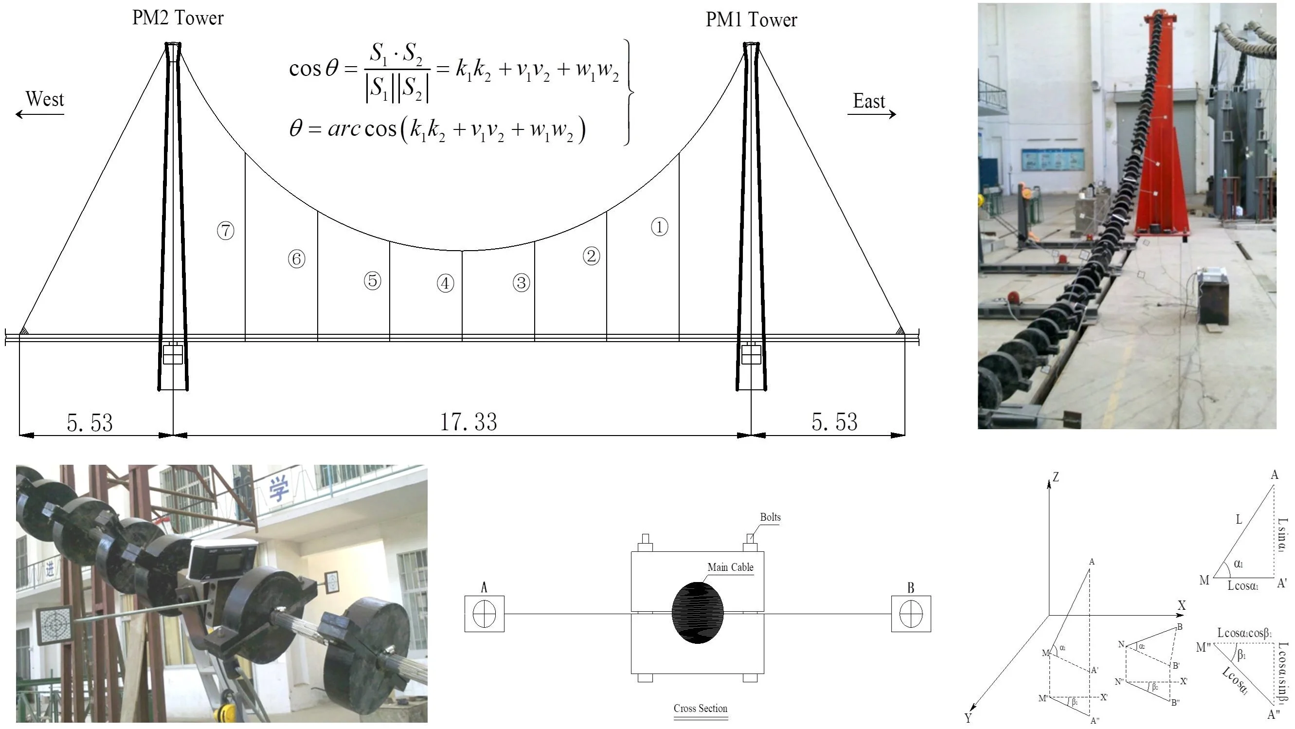
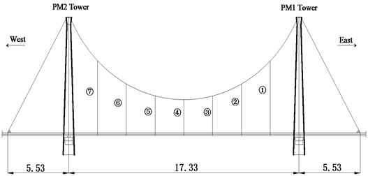
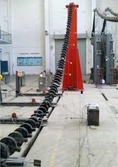
The experimental program selects a real twin-tower three-span suspension bridge located in China as the prototype bridge. Based on the configuration and geometric size of the prototype bridge, a scale-reduced suspender bridge model was designed and constructed. As shown in Fig. 1, the total length of the model bridge is 28.39 m, with a span arrangement of 17.33 m in the middle and 5.53 m on each side. The overall height of the main tower is 4.7 m for the PM1 tower and 4.8 m for the PM2 tower. No sling was set between the main girder and the main cable in the side spans. In the middle span, there are seven vertical slings with the same adjacent intervals numbered by 1), 2),… 7) from east to west between the main cable and girder. The main cable comprises 19 steel strands and is arranged in a plane layout. Each steel strand comprises seven steel wire bundles with a nominal diameter of 1.8 mm and an elastic modulus of 2.0×10⁵ MPa. The unstressed length of the main cable in the mid-span is 29.28 m, while that in the side span has a cable length of 3 m (the sum of the net length and extends into anchorage length). All the slings are fabricated using steel wire ropes with a material elastic modulus of 1.95×10⁵ MPa. The Q345qD steel (with a nominal yield strength of 345 MPa) was adopted for the main towers, saddles, and anchorage blocks. In order to simulate the geometric boundaries above the towers and allow predetermined deformation of the cable, the circular arc of the main saddle along the longitudinal direction of the bridge is set in both the façade and plane. There are two main parallel cables in the selected prototype bridge. Only a single cable was fabricated in the model bridge to ease model construction and save costs.
Fig. 1Layout of the suspension bridge model (UNIT: m)
3. Cable torsion angle measurement method and apparatus
Under the transverse tension of slings, the main cable in suspender bridges may convert from a planar state to a spatial state, accompanied by the constant changing of the cable linearity and deflection angle. In order to characterize the torsion angle of the main cable, the following two predictive methods are developed to calculate the variations in cable angles.
3.1. Coordinate method
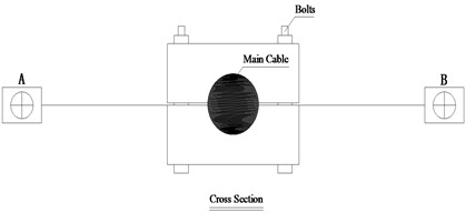
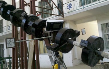
The coordinate method calculates the cable linearity and torsion angle based on the geometry relationships among the coordinates of key points. In order to obtain the critical coordinates, several key points (e.g., the sling lifting point, the midpoint between adjacent slings, and the saddle point) on the cable curve should be designated. At the location of each key point, a measurement device with two displacement observation targets is preset horizontally to characterize the displacement caused by loads. The position changes on the observation targets can be measured by the total stations. As shown in Fig. 2, the measurement device fastened to the main cable is not allowed to slide during testing, and the direction and length of the target plates on the device can be flexibly adjusted. The measurement points on the target plate center are labeled as points and (see Fig. 2).
Fig. 2Measurement device and target plates
In the measurement system, the , , and axis are along the bridge’s lateral, longitudinal, and vertical directions. Before applying the testing load to the bridge model, the total station can determine the initial coordinates of points and . After the load is applied to the bridge model, the measurement points move to the new positions and . By using the measured coordinates, the direction vector of a straight line, , of points and can be expressed as:
where is the direction vector before loading; is the direction vector after loading.
According to the cosine formula of the angle, the angle between vectors and can be determined by Eq. (2):
Analyzing the geometric relationships between the target plates makes it easy to know that the achieved is the cable torsion angle caused by loads. Normally, the torsion direction of the main cable is identical to the transverse force of the slings (positive torsion). However, during the construction of the suspenders, anti-torsion may occur at the local position of the main cable (negative torsion). The following conditions can be used to distinguish the twisting direction of the cable: (i) for 0, it is a positive torsion and designated as "+"; and (ii) for 0, it is a negative torsion and designated as "–". It should be noted that as the main cable is constantly located at the midpoint of strait line (), the introduced coordinate method can also be used to determine the cable curve at any spatial angle before and after deformation.
3.2. Angle method
The angle method determines cable torsion angle by deriving the direction vector from measured angles. Fig. 3 shows the inclinometers for angle measurement and the arrangement of the inclinometers. As can be seen, in order to precede the angle measurement, two inclinometers are fixed to the main cable at the measurement point. The L-shaped component hinged on the block can swing freely along the transverse direction, and its longitudinal and vertical directions are fixed. During the angle measurements, the position of the carrier axis changes, and the L-shaped component swing in the same plane, contributing to a constant right triangle between the L-shaped component and the carrier axis. By installing the inclinometer on the horizontal level of the L-shaped component, the angle between the projection of the carrier axis and the horizontal axis can be identified. With the help of this measurement system, the vertical angle and horizontal angle of the carrier axis on the cable can be read from the inclinometers.
Fig. 3Configuration and arrangements of inclinometers
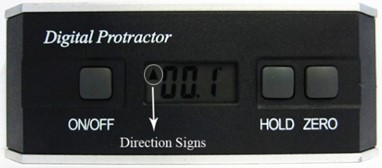
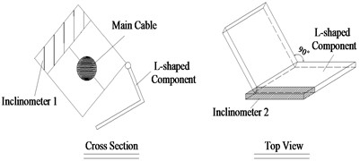
Fig. 4Angle method calculation diagram
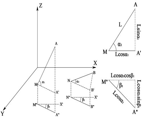
In order to obtain the cable torsion angle, it is necessary to know the vector and plane angle of the carrier axis. Fig. 4 shows the geometrical relationship between the vectors. As can be seen, the length of the carrier axis is , and the carrier axis before and after loading is and , respectively. The vertical angle was measured before and after loading and , respectively. The projection of the carrier axis in the horizontal plane is and , respectively. The angle between and is , while the angle between and is . When the arrow of the inclinometer points upward, the and in the vertical plane and the and in the horizontal plane are defined as positive, marked as "+".
Assume that the coordinate of point is , and the coordinate of point can be obtained by geometric relationship:
The change in points and is the direction vector of carrier axis :
Similarly, the direction vector of carrier axis can be obtained:
The vector length of and is the axis length of carrier , and the main cable torsion angle determined by and is:
where: , , , , , .
4. Model test and discussions
The experimental tests applied symmetrical loading to the bridge model from the middle to both sides. In order to examine the torsion angle of the main cable under different loading cases, experimental results were obtained from the bridge model when the sling and plumb line possessed an inclination angle of 12° in transverse direction under 20 % and 80 % of the design load, respectively, were analyzed. The sling transverse tensioning force triggers certain torsion in the spatial cable between the two suspension points, the midpoints between two adjacent slings, and that between the side suspender and main tower are selected as the research object. For the convenience of discussion, the selected key points from east to west are numbered 1, 2, …, and 8. Table 1 presents a summary of the experimental data measured from the model.
With the help of the above-introduced calculation procedures, the torsion angles of the main cable in the test model caused by the loads are achieved and summarized in Table 2. As can be seen, the coordinate method and angle method produced similar cable torsion angle results for the tested bridge model, showing a maximum relative error of 10.4 %. It is noticed that the difference between the calculated torsion angles for the two methods is comparatively large for the key points near side spans. This can be ascribed to the fact that under the transverse tensioning effects of the slings, the cable torsion angle is a spatial angle rather than a plane angle, and the changes in cable linearity near the towers are more significant than that near the mid-span. Table 2 also shows that the coordinate method produced torsion angle is larger than the (). This also confirms that the main cable under the three-dimensional suspender force is spatially twisted.
Table 1Measured data before and after loading
Key point number | Before loading | After loading | |||||||||
(m) | (m) | (m) | (°) | (°) | (m) | (m) | (m) | (°) | (°) | ||
1 | 1-1 | –0.223 | 0.587 | 36.011 | 16.5 | 6.3 | –0.139 | 0.521 | 35.923 | 36.0 | 21.4 |
1-2 | 0.406 | 0.685 | 36.264 | 0.337 | 0.777 | 36.343 | |||||
2 | 2-1 | 0.172 | 3.401 | 34.121 | 3.8 | 4.5 | 0.194 | 3.440 | 34.147 | 7.4 | 6.0 |
2-2 | 0.834 | 3.287 | 34.086 | 0.848 | 3.302 | 34.076 | |||||
3 | 3-1 | 0.399 | 5.458 | 33.005 | –9.5 | 2.6 | 0.423 | 5.481 | 33.005 | –4.8 | 4.0 |
3-2 | 1.049 | 5.448 | 33.131 | 1.080 | 5.453 | 33.081 | |||||
4 | 4-1 | 0.511 | 7.618 | 32.469 | 7.2 | 2.4 | 0.535 | 7.619 | 32.429 | 14.5 | 3.5 |
4-2 | 1.135 | 7.634 | 32.746 | 1.192 | 7.629 | 32.623 | |||||
5 | 5-1 | 0.487 | 10.047 | 32.636 | –2.3 | 2.0 | 0.525 | 10.036 | 32.575 | 1.4 | 3.0 |
5-2 | 1.150 | 10.065 | 32.686 | 1.190 | 10.062 | 32.582 | |||||
6 | 6-1 | 0.412 | 11.754 | 33.054 | 10.0 | 2.8 | 0.443 | 11.743 | 32.988 | 16.8 | 3.7 |
6-2 | 1.070 | 11.804 | 33.079 | 1.094 | 11.767 | 33.091 | |||||
7 | 7-1 | 0.197 | 13.913 | 34.095 | –7.8 | 5.8 | 0.209 | 13.819 | 34.187 | 4.3 | 9.5 |
7-2 | 0.852 | 13.910 | 34.218 | 0.870 | 13.904 | 34.209 | |||||
8 | 8-1 | –0.212 | 16.623 | 36.223 | 1.6 | 9.0 | –0.191 | 16.529 | 36.315 | 17.4 | 21.6 |
8-2 | 0.459 | 16.676 | 36.296 | 0.448 | 16.727 | 36.208 | |||||
Table 2Calculated torsion angle of main cable
Key point number | Angle by coordinate method (°) | (°) | (°) | Angle by angle method (°) | Angle difference by the two methods (°) | Relative error by the two methods (%) |
1 | 23.3 | 19.5 | 15.1 | 23.7 | 0.4 | 1.7 |
2 | 3.8 | 3.6 | 1.5 | 3.9 | 0.1 | 2.6 |
3 | 4.6 | 4.7 | 1.4 | 4.9 | 0.3 | 6.5 |
4 | 7.6 | 7.3 | 1.1 | 7.4 | –0.2 | –2.6 |
5 | 3.8 | 3.7 | 1.0 | 3.8 | 0.0 | 0.0 |
6 | 7.2 | 6.8 | 0.9 | 6.9 | –0.3 | –4.2 |
7 | 11.5 | 12.1 | 3.7 | 12.7 | 1.2 | 10.4 |
8 | 19.8 | 15.8 | 12.6 | 20.1 | 0.3 | 1.5 |
5. Conclusions
This paper investigates the calculation method for predicting the cable torsion angle during erecting the slings. A scale-reduced suspender bridge model was fabricated and tested to obtain the cable torsion angle. Based on the deformation characteristics of the main cable, the coordinate method and angle method to calculate the spatial cable torsion angle in suspender bridges are developed. The main conclusion drawn from this study includes:
1) Under the transverse tensioning effects of the slings, the cable torsion angle is a spatial angle rather than a plane angle, and the changes in cable linearity near the towers are more significant than that near the mid-span.
2) The proposed coordinate and angle methods produced similar torsion angles for the main cables, showing a maximum relative error of 10.4 %. Despite the capability of calculating the spatial cable torsion angles, the coordinate method also exhibits advanced capability in determining the geometric curves of the main cable under different spatial angles.
References
-
W.-M. Zhang, X.-F. Lu, Z.-W. Wang, and Z. Liu, “Effect of the main cable bending stiffness on flexural and torsional vibrations of suspension bridges: Analytical approach,” Engineering Structures, Vol. 240, p. 112393, Aug. 2021, https://doi.org/10.1016/j.engstruct.2021.112393
-
S. He, Y. Xu, H. Zhong, A. S. Mosallam, and Z. Chen, “Investigation on interfacial anti-sliding behavior of high strength steel-UHPC composite beams,” Composite Structures, Vol. 316, p. 117036, Jul. 2023, https://doi.org/10.1016/j.compstruct.2023.117036
-
C. Li, Y. Li, and J. He, “Experimental study on torsional behavior of spatial main cable for a self-anchored suspension bridge,” Advances in Structural Engineering, Vol. 22, No. 14, pp. 3086–3099, 2019.
-
W. Zhang, Z. Liu, and Z. Liu, “Aesthetics and torsional rigidity improvements of a triple-cable suspension bridge by uniform distribution of dead loads to three cables in the transverse direction,” Journal of Bridge Engineering, Vol. 26, No. 11, 2021.
-
Y. T. Zhou, Y. Q. Li, J. P. Tu, and J. F. Jia, “The design and calculation of main cable of Tianjing Fumin Bridge,” (in Chinese), Highway, Vol. 12, pp. 1–5, 2006.
-
S. He, W. Zhou, Z. Jiang, C. Zheng, X. Mo, and X. Huang, “Structural performance of perforated steel plate-CFST arch feet in concrete girder-steel arch composite bridges,” Journal of Constructional Steel Research, Vol. 201, p. 107742, Feb. 2023, https://doi.org/10.1016/j.jcsr.2022.107742
-
G. L. Zhu, X. W. Wern, and M. H. Pan, “Installation errors of three-dimension pose measurement systems,” (in Chinese), Huazhong University of Science and Technology (Natural Science Edition), Vol. 5, pp. 1–5, 2011.
About this article

The authors express their sincere gratitude for the support provided by the Changsha University of Science and Technology.
The datasets generated during and/or analyzed during the current study are available from the corresponding author on reasonable request.
The authors declare that they have no conflict of interest.
