Abstract
Based on Kirchhoff thin plate and Mindlin thick plate theories, the vibration and energy flow characteristics of clamped stiffened plate are studied by using the analytical model constructed by finite integral transform method. The results show that the energy flow characteristics of the stiffened plate at the beam/plate coupling interface depend on the position of the rib in the vibration modes of the plate. The effects of shear deformation and rotatory inertia on the energy flow across the beam/plate coupling interface of the stiffened plate are further investigated. It is found that the inclusion of rotatory inertia of the beam and plate in the model only affects the energy flow component controlled by the moment coupling but not that controlled by the shear force coupling. Whilst the inclusion of the shear deformation of the beam and plate mainly causes a decreased amplitude of the energy flow for the mode group where the beam is located away from both the nodal and antinodal lines of modes, in addition to the shear deformation of the plate which also leads to an increased amplitude of the energy flow component controlled by the shear force coupling for the mode group where the beam locates at the antinodal line of modes. The understanding of energy flow characteristics of the stiffened plate at the beam/plate interface is essential to effectively control the noise and vibration problems of structures such as transformer tanks and machine covers.
Highlights
- An integral transform solution is presented for the vibration and energy flow characteristics of clamped stiffened plate.
- Effects of shear deformation and rotatory inertia on the energy flow across the beam/plate coupling interface of the clamped stiffened plate are investigated.
- Rotatory inertia of the beam and plate affects the energy flow component controlled by the moment coupling but not that controlled by the shear force coupling.
- Shear deformation of the beam and plate mainly causes a decreased amplitude of the energy flow for the mode group where the beam is located away from both the nodal and antinodal lines of modes.
1. Introduction
Beams, plates and their coupled forms are the fundamental structural components in marine, aerospace, vehicle transportation engineering and other fields. The average vibration energy of these structures is often used to describe their vibration and acoustic radiation characteristics at middle and high frequencies. Therefore, energy-based analysis methods are generally used for the study of the mid- to high-frequency vibroacoustic response of stiffened plate structures currently, which mainly include statistical energy analysis (SEA) and energy flow analysis (EFA). EFA is a propagation wave method based on an energy equation, while SEA is a modal method. For example, Langley et al. [1] investigated the vibration energy transmission characteristics of periodically stiffened plates using SEA and analyzed the effect of periodic spacing of stiffeners on energy transmission. Bercin [2] investigated the effects of shear distortion and rotary inertia on the flexural energy transmission of a stiffened plate structure using the direct-dynamic stiffness method and SEA, and showed that energy flow decreases significantly compared with the transmitted energy calculated using the classical thin plate theory. Lin et al. [3] applied SEA method to study vibration energy transmission in L-shaped plates with fully simply supported boundary and calculated the energy flow between plates under definite force and moment excitation conditions.
Wester and Mace [4-6] developed a wave-based method for the analysis of energy flow in deterministic models involving two- and three-dimensional subsystems as well as complex uncertain structures, and then analyzed the energy flow in coupled structures comprising two regularly or irregularly rectangular plates. Li et al. [7] investigated vibrational wave and energy flow characteristics of infinite thin plate of finite width with a part-through surface crack base on wave method, and considered modeling the crack as a linear spring whose elasticity was derived from the relationship between strain energy and stress intensity factor in fracture mechanics. They showed that the vibrational energy flow of cracked plate is highly related to the depth and location of the part-through crack. In addition, Pany et al. [8-11] investigated wave propagation and free vibration of plate and shell structures based on the wave method and finite element method. For example, Pany et al. [8] solved the natural frequencies for a circular cylindrical shell in radial vibration using a wave propagation method. They found that the bounding frequencies and the corresponding modes in all the propagation bands can be determined by choosing a proper periodic element, and all the natural frequencies of a row of curved panels with simply supported extreme edges can be determined from the phase frequency curves. Pany and Parthan [9] investigated wave propagation along the axis of an infinite cylindrical curved plate supported at a regular interval to determine its natural frequency in bending vibration using two approximate methods, one of which uses beam functions and sinusoidal modes form of bending deflection to obtain propagation constant curves, and the other uses a high-precision trigonometric finite element in conjunction with the wave method to determine natural frequencies. Pany [10] investigated the propagation of free waves in a two-dimensional periodic plate using the finite element method combined with Floquet’s theory (periodic structure concept), which can be used to solve for the natural frequency of a finite multi-supported flat plate with internal line supports by discretizing the propagation band. Pany and Parthan [11] studied the free vibration of a multi-supported finite curved panel continuous in circumferential and axial directions using high-precision triangular finite element. Zhang et al. [12] formulated the dynamic model of periodically coupled plate structure using the dynamic stiffness method (DSM), which is a powerful tool for vibration analysis of periodic plate structure due to its efficient substructure coupling technique. It is found that the DSM can obtain accurate results with much less computational time than the finite element method.
Cotoni et al. [13] extended the energy flow approach to sound transmission problems through a finite plate. Seo et al. [14] developed a power flow analysis method to predict the vibration response of reinforced plate structures with simply supported boundaries from moderate to high frequencies and analyzed the power transmission and reflection coefficients at the coupled plate/beam interface. Song et al. [15] analyzed vibrational energy and intensity distribution of the coupled beam-plate structures by EFA in medium-to-high frequencies ranges. Han et al. [16] developed EFA method to predict the vibration energy density of the thin plate with mean flow in the high frequency range. Ma et al. [17] studied the medium frequency vibration of a built-up plate structure by EFA and calculated mode count, modal density, damping and coupling loss factors and input mobility of plate structures. Zhu and Yang [18] investigated the power flow characteristics and energy transmission of variable stiffness laminated composite plates with curvilinear fibres subjected to harmonic excitation using the finite element method based on the vibration power flow analysis. They indicated that the fibre angles can be tailored to change the vibration transmission paths according to the specific excitation. Zhou et al. [19] investigated the vibration energy flow transmission behavior of laminated composite plate structures coupled with a line hinge using the substructure-based power flow analysis method and analyzed the effects of the fiber orientation, boundary conditions and the position of coupling hinge on the vibration transmission path. Teng et al. [20] calculated the energy density of the laminated plate with free damping layers under high-frequency excitation based on EFA and analyzed the effects of the loss factor and the thickness of the damping layer on the energy density.
In addition, there are several other methods used to analyze the vibration energy transmission and sound energy transmission of plates and beams. Krishnappa and McDougall [21] investigated sound intensity distribution and energy flow in the nearfield of a clamped circular plate vibrating at its resonant frequencies using Rayleigh's integral formula and finite difference method, and analyzed sound energy flow of the axisymmetric modes and sound intensity distributions of non-axisymmetric modes. Cieślik and Bochniak [22] presented a numerical analysis method of structural intensity distribution to analyze the vibration energy flow across a stiffened rectangular plate with simply supported boundary conditions. Pavić [23] presented a model of a beam-plate system for studying the distribution of vibration energy and energy flow in beams and rods under excitation sources using numerical method. They showed that axial vibration is of equal importance to transverse vibration in terms of energy flow of beams. Bercin [24] analyzed the effects of in-plane vibrations on the energy transmission in plate-type structures using the dynamic stiffness technique and showed that excluding in-plane modes may lead to large errors in energy prediction unless the structure is very simple. Han et al. [25] developed a transfer function method and an impedance method for calculating the energy response of simply supported beams and plates excited by discrete random forces. Weaver [26] calculated the average square response of an infinite homogeneous plate with undamped sprung massed distributed randomly based on diagrammatic multiple-scattering theory. They found that the radiative transfer equation governs the energy flow on time scales larger than the frequency inverse, while the diffusion equation governs the energy flow at times larger than the residence time of the energy in the substructure. Kessissoglou [27] investigated active attenuation of the plate flexural wave transmission through a reinforcing beam on a semi-infinite simply supported stiffened plate. They showed that significant attenuation of all the resonance peaks in the flexural wave transmission can be achieved by using a single force and a single moment collocated on the beam. Sorokin [28] studied the vibration and energy propagation in an infinitely long fluid-loaded sandwich plates bearing concentrated masses and supported by springs based on the sixth order theory of multilayered plates coupled with the standard theory of linear acoustics. It is found that inclusions responding to transverse motions do not affect the energy propagation in sandwich plates with a soft core. Xu et al. [29] analyzed the transmission of vibration energy flow in simply supported stiffened plates using the structural intensity method and showed that the existence of stiffeners can change the energy flow in plate. Wang et al. [30] investigated the power flow characteristics of a complex plate-cylindrical shell system using the substructure method. Zhu et al. [31] investigated the vibration transmission and power flow behaviour of harmonically excited laminated composite plates attached with an inerter-based suppression device based on the substructure method and analyzed the effects of fibre orientations and different lamination schemes on vibration power flow input and transmission as well as the kinetic energy. Tang et al. [32] presented the method of reverberation-ray matrix for the free vibration analysis of plate/shell coupled structures based on the classical thin plate theory and the Flügge thin shell theory, but the method is only applicable to the plate/shell coupled structures where the plate is simply supported boundary conditions on both opposite sides. Wang et al. [33] calculated the bending coupling loss factor of L-shaped plate using finite element method (FEM), and analyzed the effect of the plate length, internal loss factor, concentrated mass and boundary condition on coupling loss factor. It is found that the energy of longitudinal and transverse waves increases sharply with the decrease of plate length, and then the accuracy of the coupling loss factor calculated using FEM decreases.
The above analysis of energy flow of stiffened plate structures is basically focused on the simply supported boundary. Moreover, the analytical solution for stiffened thin plates with fully clamped boundary based on the wave method is currently available [34], but the vibration energy flow of stiffened thick plates has not been analyzed and investigated. Therefore, based on the finite integral transform technique [35], an analytical model is established for the analysis of the vibration energy flow of stiffened thin and thick rectangular plates with fully clamped boundary at medium and high frequencies. The natural frequencies and input mobilities of a stiffened rectangular plate are calculated using the developed analytical model, and the accuracy of the model is validated by the finite element and propagation wave method [34]. The energy flow characteristics across the beam of the stiffened plate are classified into three categories according to the vibration modes, and the effects of transverse shear deformation and rotatory inertia on the energy flow at the beam/plate coupling interface are investigated.
2. Formulations of the stiffened plates
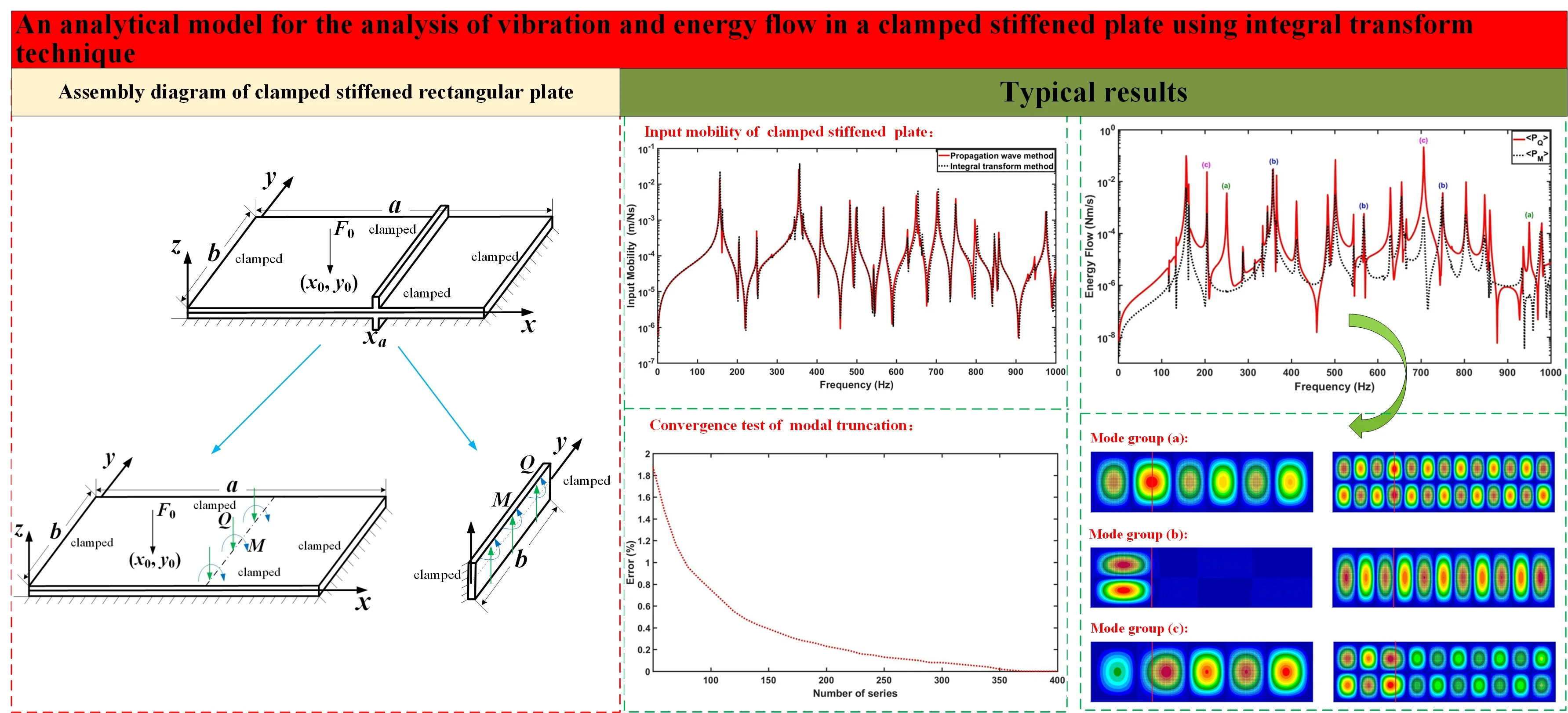
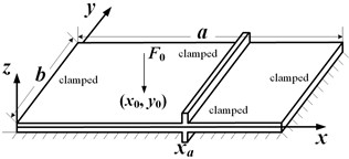
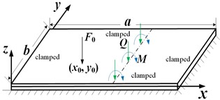
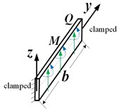
A structural model of a fully clamped stiffened rectangular plate is shown in Fig. 1. The stiffener is a beam structure of rectangular cross-section inserted symmetrically into the plate structure. It is assumed that the insertion position of the beam is parallel to the direction of the -coordinate of the plate (). The internal force components at the coupled boundary of the plate and beam are also shown in Fig. 1, where is the shear force per unit length and is the moment per unit length. is the amplitude of a point excitation source applied at position .
Fig. 1a) A graphic illustration of a fully clamped stiffened rectangular plate, b) the base plate and the coupling force and moments at the interface, c) the stiffening beam
a)
b)
c)
2.1. Analytical solution of clamped stiffened Kirchhoff plate
Based on the finite integral transform method [35], the analytical solution of vibration response of a stiffened rectangular thin plate with fully clamped boundary is given in this subsection. In addition, Kirchhoff thin plate theory is employed for the plate structure, and Euler-Bernoulli thin beam theory is in the beam structure. For a steady state vibration, the governing equation of the bending displacement () of stiffened plate under the point force excitation can be reduced to [36]:
where are the bending stiffness of the base plate, in which is the thickness, is the surface mass, and is the angular frequency.
For a stiffened thin plate with fully clamped edges, the analytical solution of the vibration response is obtained using a finite sine integral transform, whose Fourier transform integral pair is [35]:
The governing equations for the flexural () and torsional () displacements of the thin beam can be written as[36]:
where and are the flexural and torsional wavenumbers, and are the flexural and torsional stiffness.
Similarly, the Fourier transform pairs of bending and torsional displacements of a clamped thin beam write [35]:
The two-dimensional finite sine integral transform as shown in Eq. (2) is applied to each term of the governing equation shown in Eq. (1), and then substituting its boundary conditions [36], the vibration response solution of the stiffened rectangular thin plate with fully clamped boundary under the excitation force can be obtained as:
where:
Accordingly, a single finite sine integral transform as shown in Eqs. (6) and (8) is performed for each term of the governing equations shown in Eqs. (4) and (5), respectively, and then substituting its boundary conditions [36], the vibration response of the thin beam on the plate is solved as:
where and . and can be determined by the boundary conditions of the clamped thin beam [36].
2.2. Analytical solution of clamped stiffened Mindlin plate
Cremer et al. [37] suggested that the thin plates model is applicable to the vibroacoustic predictions of plates where the ratio of the bending wavelength of the plate to its thickness is greater than a factor of six. However, even if the plate is very thin, vibroacoustic predictions can be subject to large errors near the applied position of concentrated force or at the medium to high frequencies. Therefore, Zhang and Lin [38] revised the criteria for the thin plates model by Cremer [37], pointing out that the standard for using the thin plate model should be doubled, that is, the bending wavelength to thickness ratio of the plate is greater than 12, in order to achieve a prediction error of less than 5 %. Based on the finite integral transform method, the analytical solution of vibration response of a stiffened rectangular thick plate with fully clamped boundary is given in this subsection. In addition, Mindlin thick plate theory is employed for the plate structure, and Timoshenko thick beam theory is in the beam structure. The thick plate theory is a first-order shear deformation theory, which is applicable to investigate the vibration of moderately thick plates with thickness not exceeding twenty percent of the shortest planform dimension [39]. For a steady state vibration, the governing equations of the bending displacement () and rotation angles and of the normal with regard to the x and y coordinates for stiffened plate under point force excitation can be described as [40]:
where is the shear stiffness of plate, and is the area moment of inertia per unit length of plate.
The normal transform for the bending displacement and rotational displacements , of the Mindlin thick plate using the two-dimensional finite sine integral transform can be represented as [35]:
Their inverse transforms are:
The governing equations for the flexural displacement , rotation angle and torsional displacement of the thick beam write[40]:
where is the mass density of beam, is the cross-sectional area of beam, and is the area moment of inertia of beam. and are Young’s modulus and shear modulus, and is the shear coefficient.
The normal transform for the transverse displacement , the rotation angle and the torsional displacement of the Timoshenko thick beam using the one-dimensional finite sine integral transform can be written as [35]:
Their inverse transforms are:
Each term of the governing equations (Eqs. (13-15)) of the Mindlin plate is transformed by the corresponding two-dimensional finite integral transform shown in Eqs. (16-18), and then substituting their boundary conditions [40], the vibration response solution of the stiffened rectangular thick plate with fully clamped boundary under the excitation force is derived as:
where:
Meanwhile, applying the corresponding one-dimensional finite integral transform as shown in Eqs. (25)-(27) to each term of Eqs. (22)-(24), and substituting their boundary conditions [40], the vibration response solution of the thick beam on the plate is:
where . and can be solved by the boundary conditions of the clamped thick beam [40].
3. Numerical evaluation
This section is to verify the accuracy of the analytical models presented in the previous section for stiffened thin and thick plate with fully clamped boundary. The material properties and structural parameters of the plate and beam structure of a stiffened rectangular plate in the numerical study are shown in Table 1. It is assumed that the beam is inserted into the rectangular plate at position 1 m, and the unit normal point excitation force is applied at position (0.6 m,0.3 m). In the simulation calculation of frequency response, the frequency resolution is 0.1 Hz.
Table 1Structural parameters and material properties of the plate and beam
Length and width of plate | Thickness of plate | Cross-sectional area of beam | Density | Young’s modulus | Poisson’s ratio | Loss factor |
3.6 m 1 m | 0.02 m | 0.08×0.02 m2 | 2660 kg/m3 | 7.1e10 Pa | 0.3 | 0.001 |
3.1. Natural frequencies
First of all, the first 20 natural frequencies of the stiffened thin plate with the fully clamped edges calculated using integral transform technique are compared to those calculated using finite element analysis (FEA) and propagation wave approach (PWA) based on Kirchhoff thin plate theory, which are listed in Table 2. In the finite element simulation, the base plate is meshed by 180×50 shell elements so that there are more than eight elements per bending wavelength at the highest frequency of concern. The ribs are meshed accordingly to match up with the plate mesh. Each node of the plate and beam elements has 6 degrees of freedom, including 3 degrees of freedom for displacements and 3 degrees of freedom for angles in , , and respectively. The plate and beam are connected by sharing nodes in FEA. It is shown that the relative difference of the modal frequencies calculated using the different approaches is within 2 % for all 20 modes under investigation, where the error is calculated using the results of the current method for the stiffened thin plate as a benchmark. The modal frequencies calculated using the current method are slightly higher than those of the corresponding modes using the propagation wave approach, indicating that the analytical model developed in this study is slightly stiffer in general than that using the propagation wave approach.
Table 2Natural frequencies of the first 20 modes of the stiffened plate structures
Mode No | 1 | 2 | 3 | 4 | 5 | 6 | 7 | 8 | 9 | 10 |
Thin beam /thin plate | 117.2970 | 133.6152 | 157.4177 | 163.1629 | 205.0329 | 250.6276 | 288.3759 | 315.4649 | 333.8181 | 344.8050 |
FEA | 116.0585 | 132.2859 | 155.1353 | 162.0501 | 202.5277 | 245.8025 | 285.2849 | 310.9836 | 329.1488 | 341.2128 |
Error ( %) | 1.06 % | 0.99 % | 1.45 % | 0.68 % | 1.22 % | 1.93 % | 1.07 % | 1.42 % | 1.40 % | 1.04 % |
PWA [34] | 116.3483 | 132.6946 | 156.2238 | 162.5179 | 204.2924 | 249.0644 | 287.9310 | 313.9991 | 331.4020 | 344.8195 |
Error (%) | 0.81 % | 0.69 % | 0.76 % | 0.40 % | 0.36 % | 0.62 % | 0.15 % | 0.46 % | 0.72 % | 0.00 % |
Thick beam /thin plate | 117.2673 | 133.5897 | 157.1762 | 163.1187 | 205.0051 | 250.5731 | 288.2267 | 315.1864 | 333.5372 | 344.3693 |
Error (%) | 0.03 % | 0.02 % | 0.15 % | 0.03 % | 0.01 % | 0.02 % | 0.05 % | 0.09 % | 0.08 % | 0.13 % |
Thin beam /thick plate | 116.9693 | 133.0809 | 156.7931 | 162.5141 | 203.6388 | 248.3967 | 286.5865 | 313.3714 | 331.4918 | 342.4816 |
Error (%) | 0.28 % | 0.40 % | 0.40 % | 0.40 % | 0.68 % | 0.89 % | 0.62 % | 0.66 % | 0.70 % | 0.67 % |
Thick beam /thick plate | 116.9023 | 133.0416 | 155.9205 | 162.3656 | 203.4258 | 247.8000 | 286.2973 | 313.1879 | 331.2329 | 342.3908 |
Error (%) | 0.34 % | 0.43 % | 0.95 % | 0.49 % | 0.78 % | 1.13 % | 0.72 % | 0.72 % | 0.77 % | 0.70 % |
Mode No | 11 | 12 | 13 | 14 | 15 | 16 | 17 | 18 | 19 | 20 |
Thin beam /thin plate | 357.5669 | 366.0314 | 410.9364 | 412.3221 | 470.4234 | 484.4397 | 501.7932 | 543.8724 | 568.1331 | 613.0749 |
FEA | 353.3012 | 360.2278 | 404.6380 | 405.3317 | 462.2912 | 476.4591 | 491.7497 | 534.6097 | 559.6128 | 601.5438 |
Error (%) | 1.19 % | 1.59 % | 1.53 % | 1.70 % | 1.73 % | 1.65 % | 2.00 % | 1.70 % | 1.50 % | 1.88 % |
PWA [34] | 355.1865 | 363.5154 | 408.8164 | 410.7373 | 468.6566 | 483.0754 | 498.6525 | 542.5303 | 567.9249 | 612.0169 |
Error (%) | 0.67 % | 0.69 % | 0.52 % | 0.38 % | 0.38 % | 0.28 % | 0.63 % | 0.25 % | 0.04 % | 0.17 % |
Thick beam /thin plate | 357.2534 | 365.9982 | 410.5394 | 412.1816 | 469.9265 | 484.1766 | 501.5539 | 543.1513 | 568.0211 | 612.7629 |
Error (%) | 0.09 % | 0.01 % | 0.10 % | 0.03 % | 0.11 % | 0.05 % | 0.05 % | 0.13 % | 0.02 % | 0.05 % |
Thin beam /thick plate | 354.7001 | 363.1441 | 409.3298 | 408.7895 | 465.5134 | 480.3375 | 496.8309 | 538.1847 | 562.5051 | 605.7633 |
Error (%) | 0.80 % | 0.79 % | 0.39 % | 0.86 % | 1.04 % | 0.85 % | 0.99 % | 1.05 % | 0.99 % | 1.19 % |
Thick beam /thick plate | 354.2919 | 362.6283 | 406.7519 | 408.5519 | 464.7690 | 479.8248 | 492.7883 | 536.4725 | 562.4874 | 605.4453 |
Error (%) | 0.92 % | 0.93 % | 1.02 % | 0.91 % | 1.20 % | 0.95 % | 1.79 % | 1.36 % | 0.99 % | 1.24 % |
Subsequently, based on the analytical model of the stiffened Kirchhoff or Mindlin plate with fully clamped boundary, the first 20 natural frequencies of the thick beam stiffened thin plate, thin beam stiffened thick plate and the thick beam stiffened thick plate, and their deviations from the first 20 natural frequencies of the thin beam stiffened thin plate are also calculated. It can be found that the deviation between them shows an increasing trend as the frequency increases, which is as expected that the stiffened thin plate model is only good for low frequency vibration prediction [38].
3.2. Input mobilities
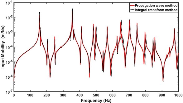
The input mobilities of the stiffened thin plate due to a unit point force excitation using finite integral transform technique and propagation wave technique are compared in Fig. 2. It is shown that the frequency responses of the stiffened thin plate using the two different techniques agree well with each other. There is some deviation between them at the higher peak frequencies.
Fig. 2Input mobility of the stiffened thin plate under the point force excitation using two different techniques
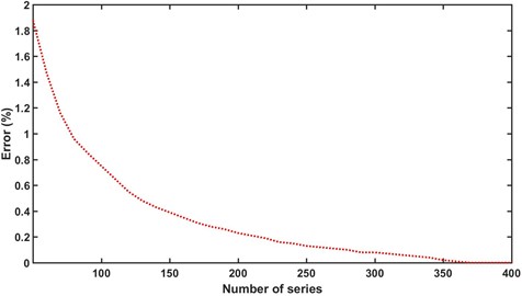
A convergent test is performed below to examine the effect of modal truncation on the accuracy of the results using the current method. In this test, the resonant frequency of the highest order mode in the 1000 Hz range is calculated using the 400×400 terms of modal truncation (400,400) as the benchmark [9]. The modal frequency of the same mode is calculated for the modal truncation number from 50×50 terms to 400×400 terms with an increment of 10×10 terms, and the errors of each calculated result from the benchmark are shown in Fig. 3. It is shown that the result converges gradually as more modal truncation terms are included in the calculation. The error induced is less than 1 % when the modal truncation number exceed 100×100 terms, while the series converges quite well when the included terms in the calculation are over 350×350.
Fig. 3A convergence test of the modal truncation for the clamped stiffened plate
3.3. Characteristics of the energy flow across the beam
The energy flow on the beam/plate interface comprises two components, one governed by the shear force coupling:
and the other controlled by the moment coupling:
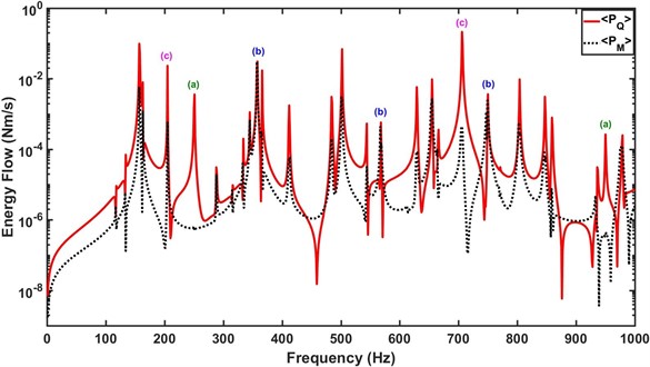
The energy flow components based on the thin beam/thin plate model across the beam due to the point force excitation applied on the plate are calculated and shown in Fig. 4. It is found that the energy flow characteristics of the beam/plate coupling interface depend on the plate vibration modes and can generally be classified into three categories: (a) modal energy flow is dominated by the shear force component where the moment component has a negligible contribution (e.g., category (a) in Fig. 4); (b) modal energy flow at the beam/plate interface is roughly carried by equal contribution from the shear force and moment couplings (e.g., category (b) in Fig. 4); and (c) modal energy flow across the beam is borne predominately by the shear force coupling, along with a noticeable contribution from the moment component (e.g., category (c) in Fig. 4). Further, it is discussed in detail how to determine the energy flow characteristics of the vibration modes of the stiffened plate at the beam/plate coupling interface.
Fig. 4The energy flow across the beam due to the point force excitation applied on the plate
Mode group (a):
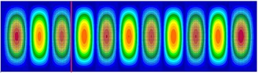
It is found that if a stiffener is inserted near or at antinode line of the modal shapes of the stiffened plate, the stiffener is subjected to larger bending deformation in the modal vibration. In this case, the shear force component dominates the energy flow across the beam. Examples of the beam position for this mode group are shown in Fig. 5.
Mode group (b):
For this group of modes, the beam is located at or close to the nodal line of the modes where the beam undergoes a very small deformation in the modal vibration. Thus, both the shear force and moment couplings contribute equally to the energy flow across the beam. Examples of the beam position for this mode group are shown in Fig. 6.
Fig. 5a) Mode shape distribution at 246 Hz, b) mode shape distribution at 921 Hz
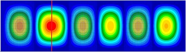
a)
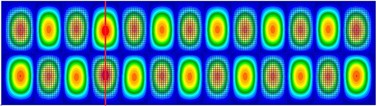
b)
Fig. 6a) Mode shape distribution at 357 Hz, b) mode shape distribution at 567 Hz
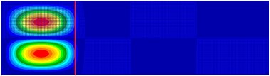
a)
b)
Mode group (c):
This group of modes can be considered as the general case of modal vibration of the stiffened plate where the beam is neither located at/near the antinode line of modes nor the nodal line of modes. For this group of modes, the beam undergoes a certain degree of bending deformation in the modal vibration, and thus the energy flow across the beam is carried predominately by the shear force coupling, while the moment coupling also provide a significant contribution. The contribution of these two coupling components to the total energy flow depends on the relative distance between the beam and the nodal line of modes. The closer the relative position of the beam to the nodal line of a mode, the greater the contribution of the moment component to the energy flow, and vice versa. Examples of the beam position for this mode group are shown in Fig. 7.
Fig. 7a) Mode shape distribution at 205 Hz, b) mode shape distribution at 683 Hz
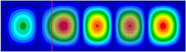
a)

b)
3.4. Effects of shear deformation and rotatory inertia on the energy flow
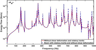
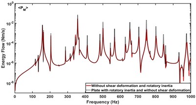
Based on the dynamic model of the clamped stiffened Mindlin plate presented in this paper, the effects of shear deformation and rotatory inertia of the beam and plate on the energy flow across the beam are investigated by setting whether the shear deformation and rotatory inertia of the beam and plate are considered in the simulation calculation. Fig. 8 compares the effect of rotatory inertia of the beam and plate on the energy flow component controlled by the moment coupling. The results indicate that the peak response frequency is hardly affected by the rotatory inertia, which is consistent with the conclusion drawn from the study of ribbed thick plates with simply supported boundary conditions [38]. It is shown that the inclusion of rotatory inertia increases the amplitude of this energy component though the peak response frequencies are almost not affected.
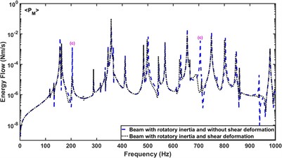
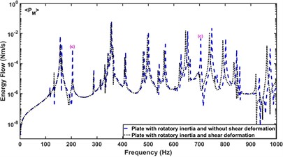
Fig. 9 compares the effect of shear deformation of the beam and plate on the energy flow component . It is shown that the inclusion of shear deformation for the beam or plate produces a large attenuation of the amplitude of the energy flow borne by in Mode group (c), but little effect on the other groups of modes. Simultaneously, compared with the energy flow without considering the shear deformation of the beam and plate, the peak frequencies of the energy flow after the plate including shear deformation are biased small and the deviation gradually increases with the increase of the studied frequency, while the shear deformation of the beam does not play a significant role in this.
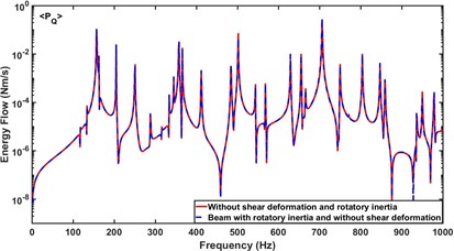
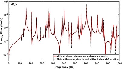
Fig. 10 compares the effect of rotatory inertia of the beam and plate on the energy flow component . As expected, it is shown that the inclusion of rotatory inertia of the beam and plate have little effect on the energy flow component controlled by the shear force coupling, and they only affect the energy flow component controlled by the moment coupling.
Fig. 8a) Effect of rotatory inertia of the beam on PM, b) effect of rotatory inertia of the plate on PM
a)
b)
Fig. 9a) Effect of shear deformation of the beam on PM, b) effect of shear deformation of the plate on PM
a)
b)
Fig. 10a) Effect of rotatory inertia of the beam on PQ, b) effect of rotatory inertia of the plate on PQ
a)
b)
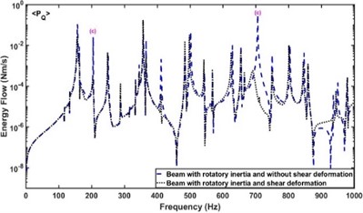
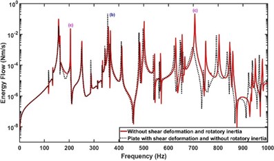
It is shown in Fig. 11 that the inclusion of shear deformation in the beam or plate causes a decreased amplitude of for modes in Mode group (c). The effect of shear deformation of the beam on the modes in other groups is less significant, as shown in Fig. 11(a). However, it is shown in Fig. 11(b) that the shear deformation of the plate can lead to an increased amplitude of for modes in Mode group (b) due to the increased deformation of the beam in the modal vibration. Further, the main research results on the effects of shear deformation and rotatory inertia of the beam and plate on the energy flow component and across the beam are summarized and listed in Table 3.
Fig. 11a) Effect of shear deformation of the beam on PQ, b) Effect of shear deformation of the plate on PQ
a)
b)
Table 3The effects of shear deformation and rotatory inertia of the beam or plate on PM and PQ
Factor | Structure | ||
Rotatory inertia | Beam | Increased amplitude | Little effect |
Plate | Increased amplitude | Little effect | |
Shear deformation | Beam | Mode group (c) | Mode group (c) |
Plate | Mode group (c) | Mode group (b), (c) |
4. Conclusions
Analytical solutions using finite integral transform technique are presented for the analysis of the vibration and energy flow of stiffened thin plates and stiffened thick plates with a fully clamped boundary. Results predicted using the current model are compared to those predicted using the FEA and PWA for validation. It is found that the vibration results predicted by all three techniques are in satisfactory agreement. The models are then utilized to study the effects of shear deformation and rotatory inertia of the beam and plate on the energy flow across the beam due to a point force excitation. Final conclusions are as follows:
1) The rotatory inertia of the beam and plate mainly affects the energy flow component , and takes very little effect on the energy flow component .
2) The shear deformation of the beam and plate causes the amplitude to decrease for the group of modes where the beam is located at neither the nodal nor antinodal lines of modes, which is the same as the effect of shear deformation of the beam on the .
3) However, the shear deformation of the plate leads not only to a decrease in the amplitude for the group of modes where the beam is located at neither the nodal nor antinodal lines of modes, but also to an increased amplitude of for the group of modes where the beam is located at the antinodal line of modes due to an increased deformation of the beam.
References
-
R. S. Langley, J. R. D. Smith, and F. J. Fahy, “Statistical energy analysis of periodically stiffened damped plate structures,” Journal of Sound and Vibration, Vol. 208, No. 3, pp. 407–426, Dec. 1997, https://doi.org/10.1006/jsvi.1997.1150
-
A. N. Bercin, “Analysis of energy flow in thick plate structures,” Computers and Structures, Vol. 62, No. 4, pp. 747–756, Feb. 1997, https://doi.org/10.1016/s0045-7949(96)00235-0
-
T. R. Lin, A. C. C. Tan, C. Yan, and D. Hargreaves, “Vibration of L-shaped plates under a deterministic force or moment excitation: a case of statistical energy analysis application,” Journal of Sound and Vibration, Vol. 330, No. 20, pp. 4780–4797, Sep. 2011, https://doi.org/10.1016/j.jsv.2011.04.015
-
E. C. N. Wester and B. R. Mace, “Wave component analysis of energy flow in complex structures – Part I: a deterministic model,” Journal of Sound and Vibration, Vol. 285, No. 1-2, pp. 209–227, Jul. 2005, https://doi.org/10.1016/j.jsv.2004.08.025
-
E. C. N. Wester and B. R. Mace, “Wave component analysis of energy flow in complex structures-Part II: ensemble statistics,” Journal of Sound and Vibration, Vol. 285, No. 1-2, pp. 229–250, Jul. 2005, https://doi.org/10.1016/j.jsv.2004.08.026
-
E. C. N. Wester and B. R. Mace, “Wave component analysis of energy flow in complex structures – Part III: two coupled plates,” Journal of Sound and Vibration, Vol. 285, No. 1-2, pp. 251–265, Jul. 2005, https://doi.org/10.1016/j.jsv.2004.08.027
-
T. Y. Li, X. Zhu, Y. Zhao, and X. F. Hu, “The wave propagation and vibrational energy flow characteristics of a plate with a part-through surface crack,” International Journal of Engineering Science, Vol. 47, No. 10, pp. 1025–1037, Oct. 2009, https://doi.org/10.1016/j.ijengsci.2009.04.003
-
C. Pany, S. Parthan, and S. Mukherjee, “Vibration analysis of multi-supported curved panel using the periodic structure approach,” International Journal of Mechanical Sciences, Vol. 44, No. 2, pp. 269–285, Feb. 2002, https://doi.org/10.1016/s0020-7403(01)00099-6
-
C. Pany and S. Parthan, “Axial wave propagation in infinitely long periodic curved panels,” Journal of Vibration and Acoustics, Vol. 125, No. 1, pp. 24–30, Jan. 2003, https://doi.org/10.1115/1.1526510
-
C. Pany, “An insight on the estimation of wave propagation constants in an orthogonal grid of a simple line-supported periodic plate using a finite element mathematical model,” Frontiers in Mechanical Engineering, Vol. 8, p. 926559, Jul. 2022, https://doi.org/10.3389/fmech.2022.926559
-
C. Pany, S. Parthan, and M. Mukhopadhyay, “Free vibration analysis of an orthogonally supported multi-span curved panel,” Journal of Sound and Vibration, Vol. 241, No. 2, pp. 315–318, Mar. 2001, https://doi.org/10.1006/jsvi.2000.3240
-
C. Zhang, H. Ding, H. Chen, G. Jin, T. Ye, and Y. Chen, “Dynamic modeling and characteristic analysis of the periodically coupled plate structure based on the dynamic stiffness method,” Results in Physics, Vol. 11, pp. 1150–1160, Dec. 2018, https://doi.org/10.1016/j.rinp.2018.11.017
-
V. Cotoni, A. Le Bot, and L. Jezequel, “Sound transmission through plates, some fundamentals,” Formulas of Acoustics, Vol. 88, No. 6, pp. 525–532, Jan. 2008, https://doi.org/10.1007/978-3-540-76833-3_156
-
S.-H. Seo, S.-Y. Hong, and H.-G. Kil, “Power flow analysis of reinforced beam-plate coupled structures,” Journal of Sound and Vibration, Vol. 259, No. 5, pp. 1109–1129, Jan. 2003, https://doi.org/10.1006/jsvi.2002.5118
-
J.-H. Song, S.-Y. Hong, Y. Kang, and H.-G. Kil, “Vibrational energy flow analysis of penetration beam-plate coupled structures,” Journal of Mechanical Science and Technology, Vol. 25, No. 3, pp. 567–576, May 2011, https://doi.org/10.1007/s12206-011-0101-0
-
J.-B. Han, S.-Y. Hong, and J.-H. Song, “Energy flow model for thin plate considering fluid loading with mean flow,” Journal of Sound and Vibration, Vol. 331, No. 24, pp. 5326–5346, Nov. 2012, https://doi.org/10.1016/j.jsv.2012.06.017
-
Y. Ma, Y. Zhang, and D. Kennedy, “Energy flow analysis of mid-frequency vibration of coupled plate structures with a hybrid analytical wave and finite element model,” Computers and Structures, Vol. 175, pp. 1–14, Oct. 2016, https://doi.org/10.1016/j.compstruc.2016.06.007
-
C. Zhu and J. Yang, “Vibration transmission and energy flow analysis of variable stiffness laminated composite plates,” Thin-Walled Structures, Vol. 180, p. 109927, Nov. 2022, https://doi.org/10.1016/j.tws.2022.109927
-
C. Zhou, J. Yang, Y. Zhu, and C. Zhu, “Energy transfer and vibration suppression of laminated composite plates coupled with a line hinge,” Mechanics of Advanced Materials and Structures, pp. 1–19, Feb. 2023, https://doi.org/10.1080/15376494.2023.2177910
-
X. Teng, Y. Han, X. Jiang, X. Chen, and M. Zhou, “Energy flow analysis model of high-frequency vibration response for plates with free layer damping treatment,” Mathematics, Vol. 11, No. 6, p. 1379, Mar. 2023, https://doi.org/10.3390/math11061379
-
G. Krishnappa and J. M. Mcdougall, “Sound intensity distribution and energy flow in the nearfield of a clamped circular plate,” Journal of Vibration and Acoustics, Vol. 111, No. 4, pp. 465–471, Oct. 1989, https://doi.org/10.1115/1.3269884
-
J. Cieślik and W. Bochniak, “Vibration energy flow in ribbed plates,” Mechanics, Vol. 25, No. 3, pp. 119–123, 2006.
-
G. Pavić, “Numerical study of vibration damping, energy and energy flow in a beam-plate system,” Journal of Sound and Vibration, Vol. 291, No. 3-5, pp. 902–931, Apr. 2006, https://doi.org/10.1016/j.jsv.2005.07.020
-
A. N. Bercin, “An assessment of the effects of in-plane vibrations on the energy flow between coupled plates,” Journal of Sound and Vibration, Vol. 191, No. 5, pp. 661–680, Apr. 1996, https://doi.org/10.1006/jsvi.1996.0149
-
F. Han, R. J. Bernhard, and L. G. Mongeau, “Energy flow analysis of vibrating beams and plates for discrete random excitations,” Journal of Sound and Vibration, Vol. 208, No. 5, pp. 841–859, Dec. 1997, https://doi.org/10.1006/jsvi.1997.1205
-
R. L. Weaver, “Mean-square responses in a plate with sprung masses, energy flow and diffusion,” The Journal of the Acoustical Society of America, Vol. 103, No. 1, pp. 414–427, Jan. 1998, https://doi.org/10.1121/1.421097
-
N. J. Kessissoglou, “Active control of the plate energy transmission in a semi-infinite ribbed plate,” The Journal of the Acoustical Society of America, Vol. 107, No. 1, pp. 324–331, Jan. 2000, https://doi.org/10.1121/1.428349
-
S. V. Sorokin, “Analysis of vibrations and energy flows in sandwich plates bearing concentrated masses and spring-like inclusions in heavy fluid-loading conditions,” Journal of Sound and Vibration, Vol. 253, No. 2, pp. 485–505, May 2002, https://doi.org/10.1006/jsvi.2001.4065
-
X. D. Xu, H. P. Lee, Y. Y. Wang, and C. Lu, “The energy flow analysis in stiffened plates of marine structures,” Thin-Walled Structures, Vol. 42, No. 7, pp. 979–994, Jul. 2004, https://doi.org/10.1016/j.tws.2004.03.006
-
Z. H. Wang, J. T. Xing, and W. G. Price, “A study of power flow in a coupled plate-cylindrical shell system,” Journal of Sound and Vibration, Vol. 271, No. 3-5, pp. 863–882, Apr. 2004, https://doi.org/10.1016/s0022-460x(03)00757-0
-
C. Zhu, J. Yang, and C. Rudd, “Vibration transmission and power flow of laminated composite plates with inerter-based suppression configurations,” International Journal of Mechanical Sciences, Vol. 190, p. 10601, 2021, https://doi.org/10.1016/j
-
D. Tang, X. Yao, and G. Wu, “Free vibration analysis of plate/shell coupled structures by the method of reverberation-ray matrix,” Journal of Vibroengineering, Vol. 18, No. 5, pp. 3117–3137, Aug. 2016, https://doi.org/10.21595/jve.2016.16950
-
C. Wang, H. B. Chen, Y. Y. Wang, and K. J. Li, “Research on high frequency vibro-acoustic response of typical structure based on finite element method,” Vibroengineering Procedia, Vol. 10, pp. 436–441, 2016.
-
T. R. Lin, “An analytical and experimental study of the vibration response of a clamped ribbed plate,” Journal of Sound and Vibration, Vol. 331, No. 4, pp. 902–913, Feb. 2012, https://doi.org/10.1016/j.jsv.2011.10.013
-
J. W. Miles, Integral Transforms in Applied Mathematics. Cambridge University Press, 1971, https://doi.org/10.1017/cbo9780511897351
-
K. Zhang, J. Pan, and T. R. Lin, “Vibration of rectangular plates stiffened by orthogonal beams,” Journal of Sound and Vibration, Vol. 513, p. 116424, Nov. 2021, https://doi.org/10.1016/j.jsv.2021.116424
-
L. Cremer, M. Heckl, and B. A. T. Petersson, Structure-Borne Sound. Berlin, Heidelberg: Springer Berlin Heidelberg, 2005, https://doi.org/10.1007/b137728
-
K. Zhang and T. R. Lin, “An analytical study of vibration response of a beam stiffened Mindlin plate,” Applied Acoustics, Vol. 155, pp. 32–43, Dec. 2019, https://doi.org/10.1016/j.apacoust.2019.05.004
-
C. W. Lim, K. M. Liew, and S. Kitipornchai, “Numerical aspects for free vibration of thick plates part I: formulation and verification,” Computer Methods in Applied Mechanics and Engineering, Vol. 156, No. 1-4, pp. 15–29, Apr. 1998, https://doi.org/10.1016/s0045-7825(97)00197-7
-
K. Zhang, T. R. Lin, H. Guo, and B. Zhang, “The effect of ribs on the sound radiation directivity of rectangular plates,” Physics of Fluids, Vol. 34, No. 12, p. 12210, Dec. 2022, https://doi.org/10.1063/5.0127918
About this article

The financial support from the Qingdao Postdoctoral Applied Research Program (No. 862205040040) of Qingdao Municipal Government of the People’s Republic of China and Doctoral Research Initiation Fund Project of Qingdao Huanghai University for this work are gratefully acknowledged.
The datasets generated during and/or analyzed during the current study are available from the corresponding author on reasonable request.
Hui Guo: investigation, software, methodology, validation, writing-original draft. Kai Zhang: conceptualization, software, methodology, validation, supervision, funding acquisition, project administration, writing-original draft, writing-review and editing.
The authors declare that they have no conflict of interest.
