Abstract
The detached raft automatic frequency isolation system is a complicated system with high exceptionally nonlinear, high electromagnetic, and multi-source vibration modes. However, it generates a statistical method and it is hard to operate the organization. The fuzzy control algorithm, as an astute control method, can give a keen path to the active management of a complicated system of floating rafts. This study uses a system identification approach to construct mathematical models for a floating raft active vibration isolation system with discrete transfer work. The fuzzy model is used in tests and simulations controller is built using two contributions of acceleration and its variation, as well as a single result of control voltage. The control isolation system is a complicated system with many moving parts. A lot of moving parts profoundly nonlinear, high electromagnetic and multi-source vibration modes, generating a statistical method and it is hard to operate the organization. The fuzzy control algorithm, as a smart control method, can give a keen path to the active management of a sophisticated floating raft system. This research uses an identification strategy to construct a floating raft active vibration isolation technology discrete transfer work mathematical models. The fuzzy controller is then put together using two contributions: acceleration and variation, as well as a single outcome of control voltage for simulations and experiments research.
1. Introduction
The vibration generated during the operation of power equipment is the primary source of mechanical equipment noise, which significantly impacts the ship’s operational ability. Vibration isolation technology is an effective means of reducing noise by inhibiting the energy transferred to the power equipment structure [1]. The active vibration isolation system of the raft has several internal structures, including the flexible characteristics of the raft frame and the nonlinear characteristics of the vibration isolator. These factors contribute to the system’s high degree of nonlinearity and coupling, making modeling and control more challenging [2]. Among them, the research of raft active vibration isolation technology mainly focuses on the two aspects of active actuator design and control strategy. The stability of the floating raft vibration isolation system and the reduction of mechanical vibration in power equipment are crucial to the ship’s performance [3]. The traditional control strategy has a high degree of dependence on the linear model, and considering the unique characteristics of the floating raft system, it will be subject to greater restrictions in the application [4]. Therefore, the research with the help of fuzzy control, an intelligent control method with high nonlinearity, can better provide a solution path for the active control of the floating raft system. At the same time, in order to avoid the subjectivity and arbitrariness of the fuzzy controller affiliation function in the selection of control rules, the study optimizes the parameters of the controller with the help of genetic algorithms in order to better improve the dynamic quality of the controller and enhance its vibration isolation effect.
2. Review of literature
To address the problem of fault diagnosis in the structure of mechanical power transmission systems, Guo et al. [5] proposed a detection means based on kernel methods and chaotic time series prediction. The results show that the method has good fault diagnosis accuracy in mechanical power transmission systems and can provide solutions for engineering practice.
Aiming at the problem of motor fault diagnosis, Zhang et al. [6] proposed a feature extraction method based on directional motion vector machine and built a sensor network scheme under the framework of cloud platform. The results showed that the method has better application effect.
Aiming at the system mechanical failure problem, Xie et al. [7] proposed a diagnostic approach that utilizes multi-sensor fusion and convolutional neural networks. The method balanced computational cost with accuracy.
The results show that the method exhibits high application accuracy. Liu et al. [8] experimentally found that the installation of floating raft vibration isolation system can effectively safeguard the vibration characteristics of marine pumps. This resulted in a significant reduction in the vibration velocity level of the pump seat, and an increase in its maximum vibration velocity by more than 80 %.
Floating raft ship structure encountered external disturbances, it is easier to produce elastic deformation. Consequently, Qiu et al. [9] established a flexible raft control response model based on the finite element, and its pressure parameters to identify to inhibit its elastic deformation results. The results showed that the method can effectively improve the control accuracy of the raft plate and reduce the deformation.
To improve the vibration isolation performance of the floating raft vibration isolation system, Weng et al. [10] proposed a dynamic model of semi-active control floating raft vibration isolation system based on the electromagnetic damping principle. They evaluated the vibration isolation effect using the vibration acceleration response and found that the control system can effectively suppress vibration and has a good simulation effect.
For the acoustic vibration coupling problem of the external body structure of the gear reducer, Jin et al. [11] analyzed the vibration transmission path relationship of the external excitation point of the body, designed the results applicable to the low acoustic vibration, and optimized the parameters with the help of dynamic modification and sensitivity analysis. The results showed that the optimized design results have better dynamic response and acoustic vibration characteristics.
The sorting of the lists into multiple groups is required for failure discovery. As a result, the clever handling equipment is used to map the features into observation options. Pattern classification, information-based guessing, and numerical presenting are examples of conventional defect diagnosis approaches. A human master searches for specific in these techniques. The presence of a bearing defect may be indicated by patterns in the vibration signature. For autonomous fault location systems, statistical analysis and Artificial Neural Network (ANN) are utilized instead.
3. Design of active vibration isolation system for mechanical gear transmission floating raft with improved fuzzy algorithm
3.1. Mathematical model of the floating raft active vibration isolation system
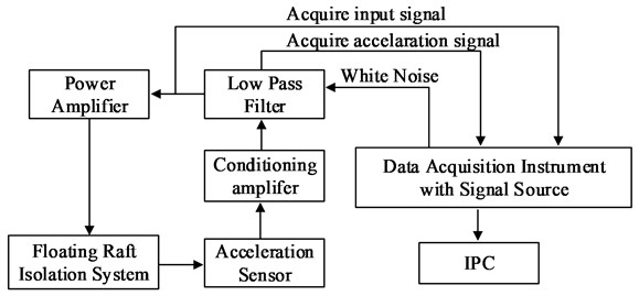
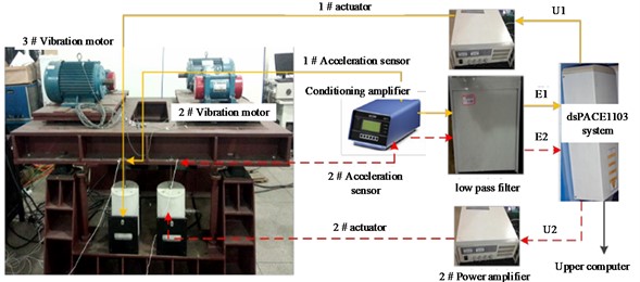
The floating raft active vibration isolation system is a kind of technical system used to reduce or inhibit floating rafts (such as marine floating platforms, ships, etc.) by external waves, wind and waves and other environmental factors, the system usually includes a variety of sensors, controllers and actuators, etc., through real-time monitoring of changes in the external environment to take the corresponding control strategy, and then regulate the dynamic characteristics of the system to improve its stability and comfort. The floating raft active vibration isolation system consists of two main components: a mechanical device and an electronic control device. Specifically, it includes an excitation motor, a motor support plate, an electromagnetic actuator, a rubber vibration isolator, a floating raft, and an inner cylinder [12]. The excitation motor is primarily used to model the vibration signal of the ship’s power equipment. The electronic control device of the system comprises a power amplifier, a low-pass filter, a conditioning amplifier, and other internal components. The data acquisition instrument in the electronic control device for input signal acquisition, and can also assume the function of signal generator. Fig. 1 shows the test apparatus for the active vibration isolation system on the floating raft.
Fig. 1Test apparatus for floating rafts with a system for active vibration isolation
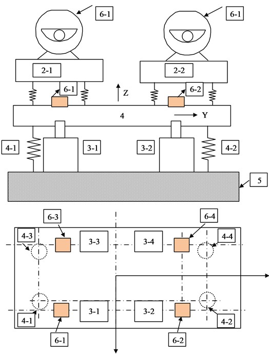
In Fig. 1, 1-1, 1-2, 1-3, 1-4 are four excitation motors, 2-1, 2-2, 2-3, 2-4 are four motor support plates, 3-1, 3-2, 3-3, 3-4 are four electromagnetic actuators, 4-1, 4-2, 4-3, 4-4 are the lower rubber vibration isolators, the upper vibration isolators, 4 is the floating raft, 5 is the foundation, 6-1, 6-2, 6-3, 64 are the four accelerometers. The active vibration isolation technique used by the floating raft is a nonlinear and solid coupling mechanism. It’s not a good idea to present a mechanism analysis because a few aim criteria such as its design and parameters are not satisfactory. The control channel’s information Mathematical models can be built using excitation data and outcome response data using the black-box system identification approach. According to the type of information and result data, the least-square approach, least to calculate, in the time-domain and frequency-domain, the mean square estimation and gradient estimation procedures are used for system identification [13]. The models used can be either non-parametric or parametric, depending on the model articulation:
where is white noise signal; by means of Z-transform it can be written as:
where and ; is lagoperator; is delay; and are order. The output content of the floating raft active isolation system system includes collected information and data. To gather this information and data, the system’s output is analyzed. The input signal is subject to background noise with a frequency range of 0-80 Hz and a voltage of 1.5 V. Before being sent to the electromagnetic actuator via a power amplifier, the background noise from the signal source is filtered using a low-pass channel [14]. To distinguish the model, use information and result data. The initial step is to choose reaction data that for processing that falls within the frequency range of 3-80 Hz. Data with a coherency of less than 0.95 should be excluded.
Fig. 2Gear transmission system with a built-in piezoelectric actuator: 1: motor, 2: gear box, 3: active control structure, 4: magnetic powder brake, and 5: base
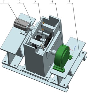
Fig. 2 shows the three-part separation of the system identification technique used in the vibration isolation system for a floating raft. The identification model’s health and stability should be examined, and its frequency response should be compared to the experimental model’s frequency response. It is necessary to note the difference between the primary operating frequency and the secondary working frequency [15]. Then, to test the stability according to post zero, models for identification should be chosen based on high welfare and low request numbers diagrams. Subsequently, the study used system identification to establish a mathematical model of the floating raft vibration isolation system. This required experimental processing of input and output data that corresponded to the system’s dynamic characteristics. The least squares method was used for identification. The input signal for system identification is required to be the data that can stimulate the modal characteristics of the system. Its noise signal is a random signal, and the main frequency range of the vibration signal of the internal power equipment is about 10-50 Hz. Fig. 3 shows the identification content of the vibration isolation device of the floating raft diagram.
In Fig. 3, the recognition process of the system consists of three main parts, the first part is to collect the data from the input and output of the system. Next, a low-pass filter with a sampling frequency of 750 Hz is used to process the white noise signal. The second part is to screen the frequency response data with coherence less than 0.95 with the help of the recognition model. Finally, the MATLAB recognition toolbox is used to process the remaining data. In the third part the fit of the discriminative model is checked. The study identifies the discrete transfer functions G11, G12, G21 and G22 between links 6-1 and 6-2 of power amplifiers 1 and 2. G11 and G12 discrete transfer capabilities between There are G21 and G22 discrete transfer capacities between a 1# amplifier and a sensor 6-1, 6-2, the following are the mathematical articulations of discrete transfer work:
Fig. 3An identification of a vibration isolation device for a floating raft diagram
In the floating raft system on a boat, multiple types of gear are typically in operation simultaneously. To replicate the conditions created by a range of devices and reflect the real environment, dual-frequency sinusoidal impulses of 25 and 45 Hz are utilized. Furthermore, during the run-time, the floating raft system will be interrupted therefore background noise is used in the simulation to handle random signal blockages to lead a MATLAB/Simu link. The discrete transfer work matrix GM is employed in a dual-channel fuzzy control simulation. To simulate the active vibration isolation system of the floating raft, a 2D fuzzy controller is used as the basic structural unit. Considering that multiple controllers will generate coupling in the control process, they need to be processed with linear iteration to suppress the error signal. Fig. 4 shows the schematic diagram of the two-channel fuzzy control simulation.
Fig. 4Diagram of dual-channel fuzzy control simulation
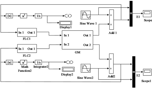
In the simulation framework in Fig. 4, FLC1 and FLC22 are conventional fuzzy controllers, E1 (the value of 6-1 accelerometer in power amplifier No. 1) and E2 (the value of 6-2 accelerometer in power amplifier No. 2), and GM is the matrix model consisting of four discrete transfer functions.
3.2. Optimization and improvement of fuzzy controller design based on GA algorithm
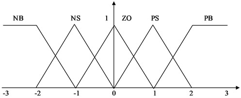
The error and blunder ratio (variation) of a two-dimensional fuzzy controller’s information variables are always selected to match the dynamic features of the managed system. The outcome variables of the item are also considered. This article uses a Mamdani-type structural model with dual-input and single-output, with acceleration and its fluctuation as data sources [16]. The fuzzy domains for the fuzzy states are PB (positive huge), PS (positive small), ZO (zero), NS (negative small), and NB (negative large). The fuzzy domains of E, EC, and U are set to [3, 3], with the fuzzy states PB, PS, ZO, NS, and NB, respectively, Ke and Kec as the quantitative acceleration and acceleration variation variables, and Ku as the scaling factor.
Fig. 5Membership function curve of E, EC, and U
Quantization factor and scaling factor are important elements for realizing the transformation between the fuzzy domain and matter theory. Providing a proportional scaling to the input and output variables is essential for regulating the control system. Factors that are too large or too small will affect the response speed, transition time, and steady-state accuracy of the system. Therefore, when setting the factors for the fuzzy control system, it is not sufficient to rely solely on the converted theoretical values. It is necessary to design certain control rules to reduce the dispersion effect of the system. Therefore, the study of optimizing fuzzy control using genetic algorithms involves two parts: applying the genetic algorithm directly to the fuzzy controller and using the genetic algorithm to process the operating state of the floating raft vibration isolation system to obtain the optimal quantization, scaling factor, and control rule parameters. The optimal parameter value is then assigned to the fuzzy controller. The fuzzy controller’s brains are fuzzy rule uses language to depict the relationship between fuzzy data and the outcome. In this article, the acceleration measurements of the floating raft vibration isolation system are utilized to determine the size of the vibration transmitted to the base [17]. The hazy control principles are then constructed based on the four acceleration change scenarios:
1) When the acceleration value is positive, and the acceleration fluctuation is small grows, more negative power is required.
2) When the acceleration value is positive, and the acceleration value is positive variance reduces, the amount of negative power required decreases.
3) Less positive power is required if the acceleration variance grows as the acceleration value decreases.
4) More positive power is required if the acceleration value is negative, and the variation in acceleration is decreasing.
The quantization and scaling factors’ function is to bridge the gap between the fuzzy and physical worlds domains, i.e., to grow or decrease the information and outcome variables by a given scale. In the control system, this transformation serves as a regulatory function. The system’s reaction speed, overshoot, transition time, and steady-state accuracy are all impaired when the quantization factors and scale factors are too big or too small. During the time period of setting quantization and scaling factors for the control system, the theoretical value that changes from the ratio of fuzzy domain to physical domain cannot produce significant control effects. It takes time to Fig. the quantization and scaling factors by trial and error [18]. The fuzzy controller receives the The blunder derivative e and the error . The fuzzy logic is used to adjust the proportional coefficient , the integral coefficient , and the differential coefficient as guidelines derivation.
As a result, the controller’s result is:
Fuzzification, fuzzy surmising, and defuzzification are the three primary aspects of the fuzzy controller’s operation. Fuzzification is the method involved with changing transforming real-world values into semantic variables. The domain of the fuzzy set is defined as the error rate of change and the variation range of the acceleration blunder . Its fuzzy set includes NB, NS, ZE, PS, and PB. Participation work can address a variety of issues the fuzzy set. They deal with negative huge, negative tiny, zero, positive small, and positive large.
As an intelligent control method, fuzzy control is robust to nonlinear, time-varying and hysteretic systems, and is therefore suitable for active control of complex floating raft systems. However, the parameter selection and design of fuzzy controllers usually depend on the experience of experts, which is difficult to adapt to the actual situation of the controlled object and lead to the optimal control effect. Moreover, fuzzy controllers are not immune to problems such as steady state error, stability and adaptability, so the study proposes to optimize the fuzzy controller with the help of genetic algorithm. Genetic algorithm, as an algorithm based on Darwin’s natural selection mechanism and the evolutionary theory of genetics, has the characteristics of good global optimization ability, implied parallelism, high robustness and self-adaptability. And the genetic algorithm is used for the parameter optimization of fuzzy controller in the floating raft active vibration isolation system, which can effectively improve the dynamic characteristics of the controller and achieve better vibration isolation effect. By using GA, the quantization factors, scale factors, and control rules are all improved simultaneously in this article. The fuzzy controller based on GA is made up of two main parts: the fuzzy controller and the fuzzy controller which controls the controlled item directly and has dynamically changing. The GA optimization method obtains parameters for the floating raft active vibration isolation system based on its operating status. The parameters include Ke, Kec, and Ku, as well as control rules. The method uses a genetic algorithm for optimization. The parameters are then inputted into the fuzzy controller [19]. In this diagram, a fuzzy controller based on the GA is shown schematically.
Fig. 6Schematic the image shows a fuzzy controller based on a genetic algorithm in this diagram
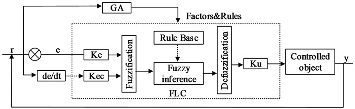
When using genetic algorithms to optimize fuzzy controllers, it is necessary to encode quantity factors, proportion factors, and control rules. Then it is necessary to determine the fitness function, chromosome selection, crossover, and mutation until the optimal population is obtained. Then the individuals in the optimal population are the optimal solution for the optimized quantity, proportional factor, and control rules of the fuzzy controller.
3.3. Simulation Design of Active Damping System for Floating Raft
In Fig. 7, a fuzzy control system with two inputs and two yields is demonstrated. Blunder signals, E1, E2, and E3, are voltage signals that correlate to the low-pass channel’s acceleration signal, as seen in Fig. 15. The separated 1# acceleration signal from the moulding is denoted by E1, the sifted 2# acceleration signal is denoted by E2, and the sifted 3# acceleration signal is denoted by E3. The A/D port of CLP1103, the dSPACE1103 system’s wiring panel, is connected to the channel yield port based on the planned controller, the DS1103 control board calculates the control amount. Because acceleration is one of the contributions for fuzzy controllers.
Fig. 7Two-input two-output fuzzy control system
Gear manufacturing errors, the cross section of gear drives can be affected by external loads, coincident collisions, and other factors. The addition of A control force close to the source of excitation can significantly reduce the quantity of excitation of excitation lattice excitation.
The piezoelectric actuator is a mechanical energy Electrical energy is converted into mechanical energy using a converter, employing the piezoelectric effect of opposing piezoelectric ceramics. Its features include high control accuracy and quick reaction time. It is commonly Position compensation, active vibration control, and precision positioning are all examples of applications.
Where indicates the actual distance between the two items during the crash, and represents the initial distance between them and represents the impact deformation. When is true, two pieces There was no collision, and the crash force was zero. The two components were affected whenever .
According to the Hertz contact hypothesis, the gear crash solidness coefficient is 0:
is the curvature radius relative:
where and are the equivalent radii of the two lattice gears’ contact sites individually, the relative radius of curvature equals:
Because the two Steel gear sets have a Poisson’s ratio of 0.27, and the Young’s modulus of the gear material is 2.07e11 Pa. The results the impact solidness coefficient KH for high-velocity gear may be calculated: KH = 5.27e5 N mm3/2. The impact solidness coefficient of the low-speed gear is KL = 5.54e5 N mm3/2. The spring is in charge of controlling the power change during the impact. The damper absorbs only a small portion of the overall crash energy.
AFPID controller is a controller with three outputs and ( and ) are two inputs (, , and ). The acceleration of vibrations is incorrect. The following three components are included in the planning and construction of a multistage gear train vibration active control test platform’s active control structure, control system, and signal acquisition and handling system [20].
4. Experiment analysis
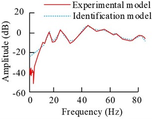
The signals from the operation of the floating raft in the power plant can be considered as periodic sinusoidal disturbances. Therefore, the study evaluates the effectiveness of the floating raft vibration isolation system at different frequencies and different acceleration signals with the help of several sets of sinusoidal signals with different frequencies as simulated disturbance signals. With the help of Simulink 8.3 toolbox, the sequence model is constructed by discrete transfer function with amplitude of 1 m/s2, sampling time of 1/750 sec and simulation time of 2.5 seconds. The coherence function value of the causal relationship between the input and output signals to be ensured by the system during the identification process is 1. The discrete transfer functions between power amplifiers No. 1 and No. 2 and the sensor link are subsequently analyzed and the results are shown in Fig. 8.
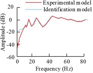
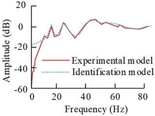
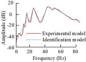
Fig. 8Comparison results of the frequency response of the two models
a) G11
b) G12
c) G21
d) G22
The results in Fig. 8 show that the overall fit between the discriminative model curves and the experimental curves in the frequency domain is better. The fits of the G11, G12, G21 and G22 curves are 90.38 %, 94.05 %, 92.46 % and 93.71 %, respectively, and their fits are all over 90 %. And the stability of the discrete transfer function model performs well.
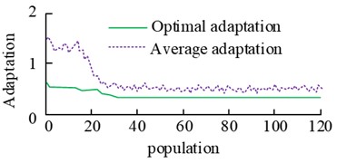
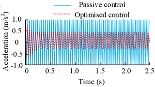
Subsequently, the disturbance signals of the power plant under single input and output conditions are analyzed, and different fuzzy controllers were set up to suppress them. The vibration acceleration values of sensors at different speeds are collected. At the same time, considering the frequency domain discretization and frequency interference of multi-frequency signals in discrete spectrum analysis, it is more likely to produce error results. Therefore, the study evaluates the effect by controlling the changes in the amplitude of vibration acceleration before and after control. Without considering the actual acceleration magnitude, this to some extent weakens the error results caused by data processing. It sets the initial population of the genetic algorithm as 150, the number of iterations is 120, and the simulation controller needs to be updated once each time to get the parameter-optimized single-frequency perturbation unidirectional input-output control results. It is shown in Fig. 9.
Fig. 9Iterative process of genetic algorithm optimisation and control simulation results under 25 Hz disturbance
a) Change in fitness of genetic algorithm optimisation iterations
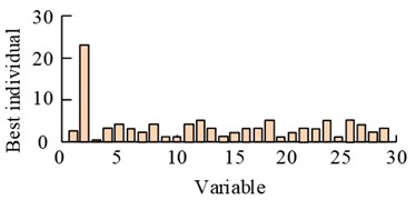
b) Best individual case of genetic algorithm optimisation iteration
c) Variation of error signal
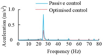
d) Simulation results before and after control
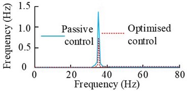
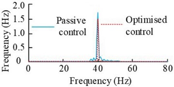
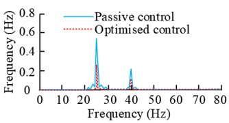
The results in the Fig. 9 show that the genetic algorithm optimized fuzzy control iteration process. When the number of iterations reaches 120 times, the average fitness value of the population reaches dynamic equilibrium. In the 90-120 times, the best individual fitness value is more stable. And the frequency domain results under this control also show that the optimized control method at the main frequency of 25 Hz error signal response amplitude results decreased by more than 65 %, compared with the value before the optimization to improve the amplitude results of 11.23 %. Subsequently the performance of the algorithm is analyzed under the narrowband perturbation model and the results are shown in Fig. 10.
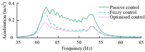
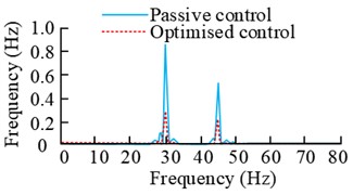
The results in the Fig. 10 show that the vibration isolation effect of the optimized controller at 40 Hz-50 Hz is significantly better than the value before optimization. It has a better suppression effect on the narrow-band signals, especially in the frequency response peak point of 42 Hz, the amplitude attenuation of the optimized controller has a difference of more than 30 % compared with that of the pre-optimized one.
The above content has been able to better demonstrate the genetic algorithm to improve the fuzzy controller has a better effect. In order to further verify that the fuzzy controller can effectively inhibit the disturbance of the power equipment of the floating raft vibration isolation system, the study chose to carry out active control experiments on the floating raft vibration isolation platform. Different fuzzy controllers are designed for different frequencies of sinusoidal signals of power equipment, in which the rotational speed of the 2# vibration motor also exists in a changing situation. The vibration acceleration value of the sensor is used as the disturbance signal before uncontrolled, and the optimized controller parameters are obtained by simulation results. Firstly, the control analysis is carried out for unidirectional input and output, and the Fig. 11 shows the control results under single frequency disturbance.
Fig. 10Error signals and simulation results of different control methods under narrowband perturbation
a) Error signals under narrowband perturbation control
b) Simulation results under narrowband perturbation control
Fig. 11Time-domain and spectral plots of the error signal and control signal at the vibration motor speed under single-frequency perturbation
a) Error signal (2100 r/min)
b) Control signal (2100 r/min)
c) Error signal (2400 r/min)
d) Control signal (2400 r/min)
e) Error signal spectrogram (2100 r/min)
f) Error signal time-frequency diagram (2400 r/min)
The results in the Fig. 11 show that the error signal increases rapidly and the control signal decreases rapidly after the beginning of the experiment, and both of them gradually converge to a stable state. When the motor speed is 2100 r/min, the amplitude at the main frequency 35 Hz before and after the control decreases from 1.405 m/s2 to 0.0744 m/s2, which is more than 40 %. When the motor speed is 2400 r/min, the amplitude change at the main frequency of 40 Hz is also more obvious, and the decrease is more than 23 %. Subsequently, the results under dual-frequency perturbation are analyzed, i.e., 2# vibration motors and 3# vibration motors are started at the same time, and the rotational speeds of motors 2# and 3# are set to be 1500 r/min and 2400 r/min and 1800 r/min and 2700 r/min in two cases. The fuzzy control results are obtained, as shown in Fig. 12.
Fig. 12Time-domain and spectral plots of the error signal and control signal at the rotational speed of the vibration motor under dual-frequency perturbation
a) Error signal (Scenario 1)
b) Control signal (Scenario 1)
c) Error signal (Scenario 2)
d) Control signal (Scenario 2)
e) Error signal spectrogram (Scenario 1)
f) Error signal time-frequency diagram (Scenario 2)
The results in the Fig. 12 show that when the rotational speeds of motor 2# and 3# are 1500 r/min and 2400 r/min, the error signal shows a rapid increase in time within 2 s, and then gradually tends to be stable with the increase of the experimental time. The control result also tends to be stable after the time is more than 2.2 s. And the corresponding frequency domain results show that before and after the control of the amplitude of the main frequency at 25 Hz decreased by 46.57 %, and the amplitude of the main frequency at 40 Hz decreased from 0.236 m/s2 to 0.165 m/s2. When the motor 2# and 3# speed of 1800 r/min and 2700 r/min, the smoothness of the control signal is obvious. The error signal is increasing within 3 s of time, and the change is obvious between 2 s and 3 s, and then it tends to be stable gradually with the time. The corresponding spectral results have peaks at 30 Hz and 45 Hz, and the amplitude decrease at these two places is more than 37 % and 58 %.
Subsequently, the fuzzy control of the bidirectional input and output is carried out, and two fuzzy controllers are designed using E1 and E2 as error feedback signals to analyze the perturbation results at single and dual frequencies. The results are shown in Fig. 13.
Fig. 13Spectra of error signals at different rotational speeds under two-way fuzzy control
a) Error signal spectrogram (1500 r/min)
b) Error signal spectrogram (2100 r/min)
c) Error signal spectrogram (2800 r/min)
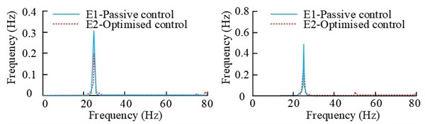
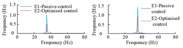
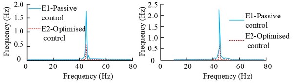
The Fig. 13 shows the spectral results of the error signals E1 and E2 when the rotational speed of the 2# vibration motor is 1500 r/min, 2100 r/min and 2800 r/min respectively. As can be seen from the Fig., when the rotational speed is 1500 r/min, the error signals E1 and E2 before and after the control reach 33.69 % and 35.52 % respectively. When the rotational speed is 2100 r/min, the values of the error signals E1 and E2 before and after the control are reduced from 1.043 m/s2 and 1.395 m/s2 to 0.9 m/s2, respectively. The magnitude reduction is obvious. When the rotational speed is 2800 r/min, the values of the error signals E1 and E2 before and after control are much higher than those of 1500 r/min and 2100 r/min, and their decreasing amplitudes are above 67 %.
5. Conclusions
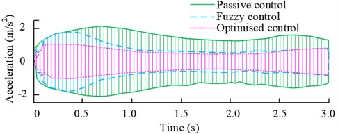
It is necessary to handle real-time changes in control parameters caused by classification to observe the control performance during the test. This area generates a unique sorting and handling mechanism. A vibration acceleration sensor, a PC, a signal conditioner, a signal gatherer, and a signal conditioner make up this system. The gearbox has a vibration acceleration sensor mounted. The signal conditioner amplifies the gathered vibration acceleration signal, which is subsequently gathered and processed by the signal gatherer. Additional supporting components connect the two piezoelectric actuators, which function together. On the information and result shafts, respectively. The angle formed by the shaft bearing and the shaft bearing controls the alignment of the force line with the lattice. The line of gear transmission is guaranteed. The sensor is plugged into the computer. The power amplifier is coupled to the piezoelectric stack actuator in signal moulding. The recorded vibration acceleration signal is employed as a passing judgement on the container vibration file; another vibration acceleration sensor is situated near the actuator’s result and provides information to the control system. The fuzzy control plan method, as well as the approach of optimizing quantitative variables, scale factors, and control handles simultaneously using real-and whole number coded half and half GA, are described. Traditional fuzzy controllers and fuzzy controllers based on GA are used to numerically simulate and verify the floating raft active vibration isolation system. The results reveal that advanced fuzzy controllers have better control impacts than traditional controllers with fuzziness. The reaction E1 and E2 blunder signals’ amplitudes reduce by more than 57.0 percent at 25 Hz and more than 61.2 percent at 45 Hz when the updated fuzzy controllers are utilized in the trials. This shows that a good isolation effect was obtained. The erroneous signal E3 also represents the foundation’s vibration response, and the results suggest that the fuzzy controller can lessen vibration.
References
-
B. Li, C. Shuai, and J. Ma, “Rolling stability analysis of high-static-low-dynamic stiffness floating raft vibration isolation systems,” Journal of Vibration and Control, Vol. 29, pp. 5161–5169, Jan. 2023.
-
J. Huang, Y. Tang, H. Li, F. Pang, and Y. Qin, “Vibration characteristics analysis of composite floating rafts for marine structure based on modal superposition theory,” Reviews on Advanced Materials Science, Vol. 60, No. 1, pp. 719–730, Sep. 2021, https://doi.org/10.1515/rams-2021-0043
-
X. Yang et al., “Dynamics and isotropic control of parallel mechanisms for vibration isolation,” IEEE/ASME Transactions on Mechatronics, Vol. 25, No. 4, pp. 2027–2034, Aug. 2020, https://doi.org/10.1109/tmech.2020.2996641
-
B. Yan, N. Yu, and C. Wu, “A state-of-the-art review on low-frequency nonlinear vibration isolation with electromagnetic mechanisms,” Applied Mathematics and Mechanics, Vol. 43, No. 7, pp. 1045–1062, Jul. 2022, https://doi.org/10.1007/s10483-022-2868-5
-
E. Guo, V. Jagota, Me. Makhatha, and P. Kumar, “Study on fault identification of mechanical dynamic nonlinear transmission system,” Nonlinear Engineering, Vol. 10, pp. 518–525, 2022.
-
X. Zhang, K. P. Rane, I. Kakaravada, and M. Shabaz, “Research on vibration monitoring and fault diagnosis of rotating machinery based on internet of things technology,” Nonlinear Engineering, Vol. 10, pp. 245–254, 2021.
-
T. Xie, X. Huang, and S.-K. Choi, “Intelligent mechanical fault diagnosis using multisensor fusion and convolution neural network,” IEEE Transactions on Industrial Informatics, Vol. 18, No. 5, pp. 3213–3223, May 2022, https://doi.org/10.1109/tii.2021.3102017
-
H. Liu, Q. Ma, Y. Li, and K. Wang, “Vibration control of a marine centrifugal pump using floating raft isolation system,” Journal of Low Frequency Noise, Vibration and Active Control, Vol. 39, No. 2, pp. 382–392, Apr. 2019, https://doi.org/10.1177/1461348419843024
-
Y. Qiu, W. Xu, W. Bu, and W. Qin, “Raft attitude control and elastic deformation suppression technique for large-scale floating raft air spring mounting system,” Journal of Vibration and Control, Vol. 28, No. 23-24, pp. 3457–3468, Aug. 2021, https://doi.org/10.1177/10775463211038830
-
Z. Weng, S. Liu, T. Xu, X. Wu, Z. Wang, and J. Tang, “Switch semi-active control of the floating raft vibration isolation system,” Strojniški vestnik – Journal of Mechanical Engineering, Vol. 68, No. 5, pp. 314–324, May 2022, https://doi.org/10.5545/sv-jme.2021.7271
-
L. Jin, J. Shao, X. Wang, Y. Wang, and B. Fu, “Vibroacoustic characteristics analysis of a planetary gear reducer considering the exterior housing structure,” Mechanical Sciences, Vol. 12, No. 1, pp. 539–557, May 2021, https://doi.org/10.5194/ms-12-539-2021
-
M. Wang, X. Ma, Y. Hu, and Y. Wang, “Gear fault diagnosis based on variational modal decomposition and wide+narrow visual field neural networks,” IEEE Transactions on Automation Science and Engineering, Vol. 19, No. 4, pp. 3288–3299, Oct. 2022, https://doi.org/10.1109/tase.2021.3117288
-
S. Dalela, P. S. Balaji, and D. P. Jena, “A review on application of mechanical metamaterials for vibration control,” Mechanics of Advanced Materials and Structures, Vol. 29, No. 22, pp. 3237–3262, Aug. 2022, https://doi.org/10.1080/15376494.2021.1892244
-
H. Li, Y. Li, and J. Li, “Negative stiffness devices for vibration isolation applications: a review,” Advances in Structural Engineering, Vol. 23, No. 8, pp. 1739–1755, Jan. 2020, https://doi.org/10.1177/1369433219900311
-
D. J. Wagg, “A review of the mechanical inerter: historical context, physical realisations and nonlinear applications,” Nonlinear Dynamics, Vol. 104, No. 1, pp. 13–34, Feb. 2021, https://doi.org/10.1007/s11071-021-06303-8
-
J. Cui, D. Zhao, S. Liu, S. Tang, L. Dong, and L. Chen, “Stability of boundary-layer flow over a skin made of porous compliant wall and micro floating raft arrays,” Ships and Offshore Structures, Vol. 18, No. 1, pp. 130–141, Jan. 2023, https://doi.org/10.1080/17445302.2022.2032991
-
D. Zhao et al., “Drag reduction characteristics of the skin made of micro floating raft arrays based on immersed boundary method,” Mechanics Based Design of Structures and Machines, Vol. 51, No. 9, pp. 4833–4846, Sep. 2023, https://doi.org/10.1080/15397734.2021.1980006
-
M. Ren, P. He, X. Xie, and Z. Zhang, “Active/passive vibration isolation with multi-axis transmission control: Analysis and experiment,” Journal of Vibration and Control, Vol. 29, No. 21-22, pp. 5090–5106, Oct. 2022, https://doi.org/10.1177/10775463221130919
-
C. Wu, J. Yang, X. Liu, and S. Jiao, “Active vibration control of heavy platform-struts structure,” Journal of Vibration and Control, Vol. 29, pp. 2752–2762, 2023, https://doi.org/10.3873/j.issn.1000-1328.2023.04.010
-
X. Li, T. Yang, W. Li, M. J. Brennan, M. Zhu, and L. Wu, “On the adaptive synchronous control of a large-scale dual-shaker platform system,” Journal of Vibration and Control, Vol. 29, No. 7-8, pp. 1644–1655, Feb. 2022, https://doi.org/10.1177/10775463211068905
About this article

The authors have not disclosed any funding.
The datasets generated during and/or analyzed during the current study are available from the corresponding author on reasonable request.
Yang Li: conceptualization, methodology, writing-original draft preparation. Guangzheng Wang: writing-review and editing, methodology, validation. Shaozhu Wang: formal analysis, investigation, data curation. Hui Tan: writing-review and editing. Fazhan Yang: data curation, formal analysis.
The authors declare that they have no conflict of interest.
