Abstract
In the long-term seismic work in Japan, an effective seismic reinforcement design system and reasonable seismic reinforcement technology have been developed, which is worth learning from. In this paper, the seismic reinforcement of a school building in Japan is taken as an example. Firstly, an overall reinforcement scheme of external prestressed precast concrete (PC) frame and steel brace is proposed. Then, based on the calculation results of seismic reinforcement and the ambient measurement before and after seismic reinforcement, the effectiveness and rationality of the seismic reinforcement method are analyzed. The results show that the seismic reinforcement method of attached substructures changes the original structural system, and solves the problems of excessive deformation and insufficient seismic performance. The reinforcement method improves the story stiffness of the structure, and the vibration period of simple harmonic motion after the implementation of seismic reinforcement is reduced by 0.845 times at most. The research results can provide reference for seismic reinforcement design and performance evaluation of existing school buildings.
Highlights
- Seismic reinforcement of a school building in Japan is taken as an example.
- An overall reinforcement scheme of external prestressed precast concrete frame and steel brace is proposed.
- Based on the ambient measurement, the effectiveness and rationality of the seismic reinforcement method is analyzed.
1. Introduction
After a rapid development phase, the Chinese construction industry has transitioned from large-scale new construction to a phase with both the new construction and reinforcement [1]. At present, the research on materials for structural reinforcement is remarkable. For example, Asharib et al. developed a high-performance hybrid fiber-reinforced concrete for the rehabilitation of bridges and buildings [2]. Saim et al. investigated the application of shape memory alloy to the reinforcement of steel-reinforced concrete structures [3]. Oluwaseun et al. used bamboo fiber laminates for structural strengthening of rusted reinforced concrete beams to improve the load bearing capacity of the members while achieving environmental protection [4]. Vitek et al. experimentally investigated the bonding and flexural properties of ultra-high-performance concrete (UHPC) during structural strengthening and verified the feasibility of its application [5].
In China, the reinforcement and disease treatment techniques for building structures are primarily following the reductionist theory of the early 1900s, with separation treatment for individual structural elements and reinforcement methods to improve the load-bearing capacity of the elements [6]. Besides, the design method of structural reinforcement is still unclear, and the study of common forces for the combined old and new parts is insufficient [7].
The Technical Regulations for Seismic Strengthening of Buildings (JGJ116-2009) emphasizes that the structure should be strengthened from the perspective of improving the overall seismic performance of the structure, and clearly states that “the overall layout of the strengthening should give priority to a program that enhances the overall seismic performance of the structure, and should be conducive to eliminating unfavorable seismic factors and improving the force state of the components” [8]. However, in engineering practice, engineers are more inclined to strengthen the components of the original structure with insufficient seismic capacity than to design strengthening solutions from the perspective of the overall seismic performance of the structure. Researchers have researched on the integrity theory and the analysis of building structural diseases [9, 10], while less researches have been done on seismic strengthening.
This study takes the seismic strengthening and renovation project of a school building in Hiroshima Prefecture in Japan as an example for the reference of similar projects. The reinforcement scheme was designed using attached substructure and local component toughness improvement to address the problems of insufficient seismic performance and the possibility of brittle damage of some components. Vibration tests were conducted before and after the reinforcement using the constant fretting test to verify the effectiveness.
2. Project profile
This building is located in Minami-ku, Hiroshima City, Japan. The Phase 1 of construction was completed in 1974, and the Phase 2 and Phase 3 were expanded in 1975. The building has 2 floors above ground, with reinforced concrete frame shear wall structure. It is used as a teaching building for a technical college. The height difference between interior and exterior is 0.45 m. The height of the first floor is 5.0 m and that of the second floor is 4.5 m. The cross-sectional size of the first-floor column is 500 mm×600 mm and for the second-floor column is 500 mm×500 mm. The cross-sectional size of the longitudinal frame beam is 350 mm×1000 mm and for the transverse frame beam is 300 mm×900 mm. The thickness of the slab is 120 mm (partial 150 mm).
Fig. 1Building model and structure layout: a) building model; b) structure layout
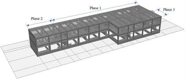
a)
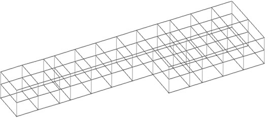
b)
In Phase 2 and Phase 3, the expansion project was partially expanded on the west and south side of Phase 1 respectively, and the Phase 1 project and the addition part were kept as a whole through the reserved frame beam joint. The foundation is an independent foundation with a burial depth of 1.4 m and a foundation bearing capacity of 130 kN/m2. The designed strength of concrete is 17.6 N/mm2, while the minimum strength of 18.3 N/m2 is presumed from the cores taken on site, and the designed strength is used for seismic identification and reinforcement calculation. The reinforcing steel is Grade I steel (SR24), and the yield strength is 294 N/m2 according to the “Standard for Seismic Evaluation and Reinforcement of Existing Reinforced Concrete Buildings” [11] by the Japan Building Disaster Prevention Association (JBDPA). The architectural model of the school building and the structural layout of the beam and column components are shown in Fig. 1.
In Japan, “all houses can fall down, but school buildings cannot fall down” is the basic principle of national earthquake disaster prevention and mitigation [12]. Since this school building was constructed during the implementation of the former seismic regulations in Japan (before 1981), and school buildings in Japan are used as emergency shelters in case of disasters in addition to ensuring normal operation of teaching work [13], the seismic evaluation and seismic strengthening of such important buildings were given priority.
3. Seismic evaluation results and existing problems
The seismic evaluation follows the principle of “the overall architecture structure first, then partial components”. Based on the utilization status, the seismic performance of the building as a whole is calculated quantitatively first, and then, the brittle damage of partial components and the conflict and collision of neighboring buildings are evaluated comprehensively.
3.1. Seismic evaluation on overall architecture structure
The 2nd diagnosis method of the current Japanese seismic identification and reinforcement regulations is adopted, and the seismic safety is determined by comparing the seismic performance of the building with the seismic performance demand index, as shown in Eq. (1):
where: is the seismic index of the building, it is a comprehensive index, which is the product of strength index, ductility index, shape index and time index; is the seismic performance demand index; is the cumulative strength index in the ultimate state, it is an indicator related to the retention of horizontal endurance. If the value is above 1.0, the risk of collapse is low, if the value is less than 1.0, there is a risk; is the cumulative strength demand index in the ultimate state. The seismic index is calculated based on the strength and ductility of the building, the regularity of the layout of the flat façade, and the ageing index.
Table 1 illustrates the calculation results of seismic index and cumulative strength index of the school building at the time of seismic appraisal and after reinforcement. The lowest value of seismic index is 0.31, and the longitudinal (-direction) seismic performance of each floor is weak, so the overall assessment result is “the possibility of collapse under earthquake is high”. Based on the seismic evaluation results of the school building and on-site confirmation, the most reasonable reinforcement and renovation plan was selected for the seismic reinforcement, as shown in Table 1.
Table 1Calculation results of Is and q before and after seismic reinforcement
Floor | ||||||||
-direction | - direction | -direction | - direction | |||||
Current | Reinforced | Current | Reinforced | Current | Reinforced | Current | Reinforced | |
2 | 0.39 | 0.81 | 0.57 | 1.30 | 1.40 | 2.85 | 2.00 | 4.59 |
1 | 0.31 | 0.77 | 0.50 | 0.86 | 1.11 | 2.70 | 1.77 | 3.04 |
3.2. Analysis of existing problems
According to the seismic evaluation results and site survey and testing, there are mainly the following problems in the seismic performance of the school building:
(1) The overall seismic performance of the school building is insufficient, especially the longitudinal walls are far from the pure frame system with less resistance to earthquakes.
(2) The overall deformation capacity of the structure is poor due to the use of Grade I steel (SR24) and the large spacing of hoop reinforcement in the concrete columns.
(3) According to the site inspection and calculation results, the poor connection between the masonry infill wall and the surrounding concrete columns can possibly result in collapse out-of-plane during an earthquake.
(4) In case of a severe earthquake, there is a possibility of “extreme brittle” damage to the individual frame column members.
(5) The design of the exterior steel staircase does not meet the structural requirements, and there is a risk of collapse during earthquakes.
Based on the results of the seismic evaluation, the overall and partial seismic performance of this building needs to be strengthened to improve safety. At the same time, the construction period and the operability of the construction machinery should be reasonably considered when selecting the reinforcement method.
4. Seismic reinforcement design
Considering the main problems of this project, the attached substructure reinforcement method was mainly adopted in combination with the school’s requirement of “reinforcement construction must be carried out during the normal use of the school building” and considering the functional requirements such as the lighting of the building. In the longitudinal direction, the overall seismic capacity was improved through the external pre-stressed prefabricated frame structure system (external PC frame) and the addition of steel bracing with frame. In the transverse direction, the carbon fiber reinforcement method (SRCF method) was used for the ductile reinforcement of lower frame columns in individual shear wall to improve the bearing capacity and deformation capacity of the frame columns. For the single column components that have a higher probability of “extremely brittle” damage during a severe earthquake, 30 mm construction joints were cut at the joints of the doors and windows on the side of the columns (the rebar was not cut) to improve the lateral deformation capacity of the components and prevent prior brittle damage. For the masonry walls inside the school building that exceed 2.0 m and were prone to collapse and damage, posing a potential risk to life safety, were demolished and replaced with lightweight Autoclaved Lightweight Concrete (ALC) panels, etc.
4.1. Attached substructure reinforcement
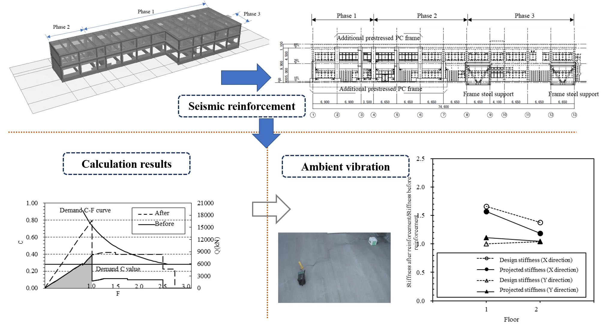
As described in the seismic evaluation results, the school building has fewer longitudinal walls, resulting in a weak longitudinal overall seismic capacity of the building. Meanwhile, considering the tight schedule of reinforcement, and not allowing structural reinforcement inside the building to affect normal teaching activities, attached sub-structure reinforcement (external pre-stressed PC frame with frame steel support) was adopted. Finally, the overall seismic capacity of the structure is improved to meet the demanded seismic index and strength index. Fig. 2 shows the structural plan and front elevation of the first floor of the reinforced solution adopted for this school building.
Externally attached prestressed PC frames were added on the 1st and 2nd floors between 1 and 7 of B axis, and framed steel supports were added on the 1st floor between 8 and 9 and 12 and 13 of A axis. The additional prestressed PC frames were combined with the original structure through cast-in-place beams, cast-in-place slabs and walls as a whole. The designed concrete strength of the prestressed components is 50.0 N/mm2, and the prestressed steel rods are SWPR7BL and SBPR1080/1230 following the Japanese “Design and Construction Regulations for Prestressed Concrete”. The combined surfaces of the PC members are made of cast grout. As shown in Fig. 3, in order to ensure the connection quality between the PC members and the cast-in-place part, the joint surface of the PC members was chiseled, while the cast-in-place connection beam was bent up in all parts except for the corners with straight reinforcement. Independent foundation was set in the additional pre-stressed PC frame to transfer the increased weight of the external attached frame.
Fig. 2Building reinforcement scheme. (Unit: mm)
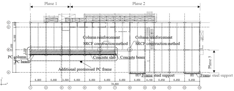
a) Ground floor plan after reinforcement
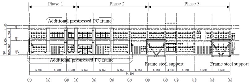
b) Front elevation after reinforcement
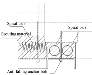
Fig. 3Joint detail of prestressed PC member
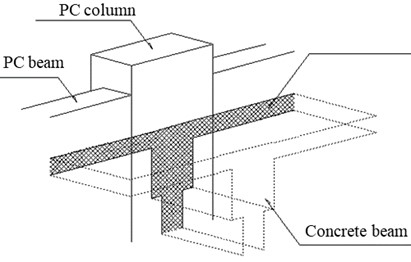
a) Details of the connection between PC and cast-in-place components
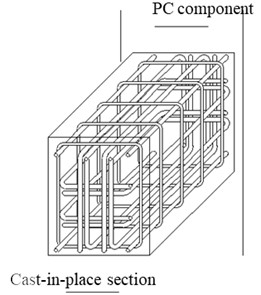
b) Details of cast-in-place connecting beams
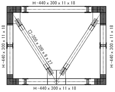
Fig. 4 shows the details of the framed steel support and the combination with the original structure beam and column used in reinforcement. Additional framed steel bracing is installed in the A-axis of the projecting part of the structure, with 300×300 angle steel pipes used for diagonal bracing and 440×300 H-beams used for the external frame. The steel brace can bear the inadequate seismic capacity after the reinforcement of the external prestressed PC frame. At the same time, because the A-axis protrudes from the structural surface, the problem of uneven distribution of the original structural plane can be improved. The V-shaped steel bracing is interlocked with the chemical anchor bars planted around the original frame through welded pins on the web of the H-shaped steel frame, with a 200mm space reserved for pouring grout and pre-buried spiral hoops on the joint surface, so that the new V-shaped steel bracing with frame remains integral with the original frame structure. The framed steel bracing sub-structure used in this project is arranged on the inner side of the 1-story frame beam and column. Due to the high stiffness of the steel bracing itself, it can provide additional necessary seismic load bearing capacity for the school building structure while improving the stress state and deformation pattern of the original structure as a whole.
Using the reinforcement method with externally attached prestressed PC frames and framed steel braced substructures, both the stiffness and load-bearing capacity of the attached substructure are considered, and the overall reasonable deformation pattern of the reinforced structure and the full utilization of the seismic capacity of the original structural members are also considered after reinforcement. The effectiveness of the reinforcement design method for additional substructures has been confirmed in other research results [14].
Fig. 4Steel brace with frame
a) Details of the connection between PC and cast-in-place components
b) Details of the connection
4.2. Partial reinforcement
In accordance with the “Standard for Seismic Evaluation and Reinforcement of Existing Reinforced Concrete Buildings” of the Disaster Prevention Association of Japan, the SRCF carbon fiber reinforcement method is used to reinforce the frame columns that are prone to “extremely brittle” damage (deformation angle less than 1/500) and the lower columns of individual shear walls whose additional axial force exceeds the ultimate bearing capacity during severe earthquakes. The carbon fiber and CF anchor bolts are of 3400 MPa level, and the on-site construction technicians need to obtain the SRCF method training certificate and have certain construction experience before they can carry out the construction work of this reinforcement method.
The masonry wall with higher risk of collapse outside the plane was demolished, and additional pillars were installed for the external overhanging steel staircase to solve the problem of insufficient resistance to vertical seismic capacity. Though the interval between the steel structure corridor on the north side and the building does not meet the seismic requirements and is prone to collision damage during horizontal earthquakes, it was not reinforced considering that the corridor is a low-weight steel structure with low risk of conflict damage to the building.
4.3. Seismic strengthening calculation results
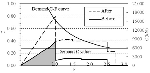
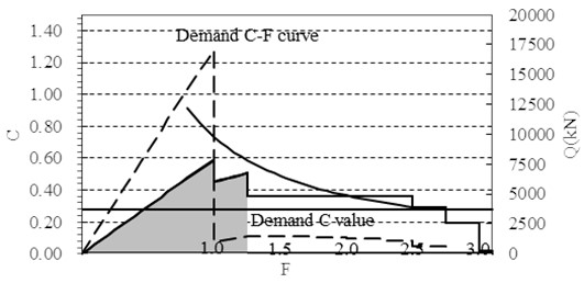
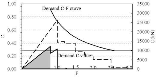
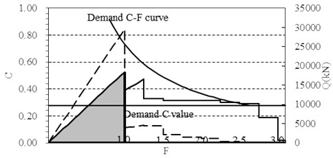
Seismic strengthening calculations were performed using BUS-6 Series Ver.1.0 (Kozo system) calculation software based on the adopted strengthening scheme. The values of seismic index and cumulative strength index are shown in Table 1 above, which satisfy the seismic requirements. The relationship between retained horizontal endurance and deformation before and after the seismic strengthening retrofit is shown in Fig. 5.
In the seismic identification and strengthening calculation, the correspondence between the strength index and the deformation index is used to comprehensively evaluate the seismic performance of the structure. Fig. 5 illustrates the C-F relationship of this school building before and after seismic strengthening. Before reinforcement, the longitudinal (-direction) seismic performance cannot meet the required C-F curve, and the transverse (-direction) barely meets the required seismic performance when the deformation index value reaches 2.5 (the deformation angle is about 1/50). However, the building needs to be seismically strengthened because the deformation capacity in the -direction can hardly reach this limit. After reinforcement, the seismic performance in the and directions was the strongest at the value of 1 (deformation angle of about 1/250) and met the required seismic performance of the design. The existing -direction in first floor has an inflection point at value of 0.8 (deformation angle of about 1/500), resulting an “extremely brittle” damage to the frame column. After carbon fiber reinforcement, the deformation capacity has been improved.
Through calculation and analysis, the overall strength of the structure was improved, and the seismic load bearing capacity met the requirements on structural safety and the seismic evaluation indexes after attached substructures were mainly adopted.
Fig. 5C-F diagram before and after seismic reinforcement
a) 2nd floor direction
b) 2nd floor direction
c) 1st floor direction
d) 1st floor direction
5. Vibration test
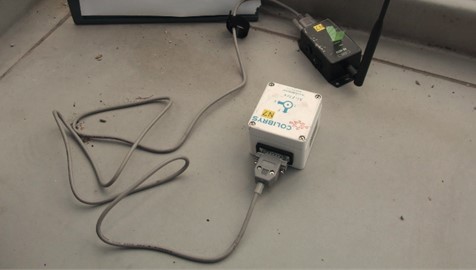
The dynamic characteristics of the structure can directly reflect the changes in characteristics before and after reinforcement [15]. Researchers evaluated the effects of reinforcement on structural dynamic characteristics based on vibration frequency and damping characteristics [16-18]. Constant micro-motion test was conducted using a wireless vibration test system before and after the implementation of the seismic reinforcement project. The sampling frequency of test wireless acceleration sensors is 100 Hz and the test interval is 30 min. Using Fourier Transform, the acquired signals were transformed to identify the vibration parameters. The effectiveness of the seismic reinforcement using attached substructures was determined using the variation of the vibration parameters. The experimental landscape of the field test is shown in Fig. 6. The field experiments were conducted using 7 wireless acceleration sensors in two categories, in the floor plane and in the vertical direction of the floor, respectively.
Fig. 6On-site vibration test
The school building was reinforced mainly with attached substructures to improve the seismic load capacity. And the significant stiffness change can be directly determined by the vibration period. Table 2 shows the change of vibration period before and after the reinforcement. In the -direction, where the attached substructure was used for reinforcement, the intrinsic period was reduced by 15.5 % and 7.1 %. Due to the increase in the overall weight of the structure, the increase in stiffness in the Y-direction is not significant, resulting in a smaller change in the intrinsic period in this direction.
Table 2Change of vibration period
Floor | Period (t/s) | Change rate (reinforced/current) | ||||
direction | direction | direction | direction | |||
Current | Reinforced | Current | Reinforced | |||
2 | 0.140 | 0.130 | 0.089 | 0.089 | 0.929 | 1.000 |
1 | 0.238 | 0.201 | 0.155 | 0.150 | 0.845 | 0.968 |
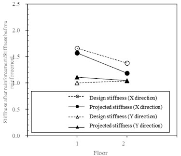
Fig. 7 shows the comparison of the projected layer stiffness with the design stiffness based on the vibration parameters comparing with the intrinsic period. The absolute value of the design layer stiffness is smaller compared to the projected stiffness, considering the reason of slight vibration amplitude under constant micro-motion. The stiffness after reinforcement increases compared with that before reinforcement, and the increase in the longitudinal direction ( direction) is greater. It can be concluded by comparison of the change rates, that the overall trend of change is consistent and the magnitude of change is approximately equal. The error of the rate of change of projected stiffness and design stiffness as shown in Eq. (2) ranges from 0.6 % to 14.0 %:
where: is the change rate of projected stiffness; is the change rate of design stiffness; is the error of the rate of change of projected stiffness and design stiffness.
Fig. 7Change of the layer stiffness
6. Conclusions
The selection of seismic reinforcement methods for school buildings is related to structural safety, serviceability, and shape, and also has restrictions on construction period and area. How to reasonably select the reinforcement method to meet the seismic requirements is worthy of in-depth study. By analyzing the seismic strengthening project of a school building in Japan, the following conclusions can be drawn:
1) The reinforcement method based on reductionism lacks rationality. The overall seismic capacity of the structure and the structural system should be given first consideration to make the reinforcement method more reasonable and standardized.
2) Attached substructures can not only improve the overall structural stiffness and seismic capacity by effectively improving the overall force pattern of the structure, but also minimize the impact on the use of the building and the change of the internal space. Both from the perspective of building function and structural safety, the attached substructure method is economic and reasonable, which is worthy of reference and popular application.
3) Based attached substructures, carbon fiber reinforcement can be used for individual components to effectively reduce the risk of local brittle damage, following the principle of “the overall architecture structure first, then partial components”.
4) The effect of the proposed reinforcement was studied by using constant micro-motion. The stiffness change verifies that the attached substructure can improve the overall strength, and the connection nodes between the original structure and the additional substructure system are effective.
While selecting the reinforcement method for existing buildings, it is necessary to consider the coordination and integrity of the existing structural parts and the new or reinforced parts.
References
-
Y. Q. Wang, L. Zong, Y. J. Shi, Hb Li, S. Liang, and H. Y. Wan, “Research advances and design specification codification of retrofitting techniques for steel structures,” Journal of Building Structures, Vol. 43, No. 10, pp. 29–40, Oct. 2022, https://doi.org/10.14006/j.jzjgxb.2022.0095
-
M. A. Shahid, M. U. Rashid, N. Ali, K. Chaiyasarn, P. Joyklad, and Q. Hussain, “Mechanical experiments on concrete with hybrid fiber reinforcement for structural rehabilitation,” Materials, Vol. 15, No. 8, p. 2828, Apr. 2022, https://doi.org/10.3390/ma15082828
-
S. Raza, B. Shafei, M. Saiid Saiidi, M. Motavalli, and M. Shahverdi, “Shape memory alloy reinforcement for strengthening and self-centering of concrete structures-State of the art,” Construction and Building Materials, Vol. 324, p. 126628, Mar. 2022, https://doi.org/10.1016/j.conbuildmat.2022.126628
-
P. O. Awoyera et al., “Structural retrofitting of corroded reinforced concrete beams using bamboo fiber laminate,” Materials, Vol. 14, No. 21, p. 6711, Nov. 2021, https://doi.org/10.3390/ma14216711
-
L. J. V. et al., “Strengthening of concrete structures using UHPC-experimental verification,” Solid State Phenomena, Vol. 322, No. 5, pp. 185–192, 2021.
-
X. Zhang and Qx Yue., “Strengthening and retrofitting of existing structures,” Building Pathology and Rehabilitation, Vol. 36, No. 5, pp. 76–82, Jan. 2018, https://doi.org/10.1007/978-981-10-5858-5
-
X. Zhang, Aq Li, and Kz Zhao., “Advances in assessment and retrofitting of buildings,” Engineering Mechanics, Vol. 28, No. 1, pp. 1–11, 2011.
-
“Technical specification for seismic strengthening of buildings,” JG J116-2009, 2009.
-
K. F. Xia and Q. C. Li, “Analysis of the overall performance of the uniformly-twisted building structure,” in Structural Engineers, Vol. 37, No. 6, pp. 18–25, 2021.
-
J. P. Han and L. H. He, “Global collapse resistance capacity analysis on earthquake-damaged reinforced concrete frame structures retrofitted with CFRP,” World Earthquake Engineering, Vol. 36, No. 1, pp. 8–16, 2020.
-
“Guidelines for seismic retrofit of existing reinforced concrete buildings,” The Japan Building Disaster Prevention Association, 2001.
-
Y. Yang, “Dormitory safety policies in Japan and the United States and its implications,” Tsinghua Journal of Education, Vol. 39, No. 2, pp. 69–75, 2018.
-
X. Y. Zhang, Y. J. Li, and Z. T. Wang, “Utilization of school shelters in east Japan earthquake and its enlightenment,” Journal of WUT (Information and Management Engineering), Vol. 44, No. 5, pp. 709–717, 2022.
-
X.-Y. Cao, D.-C. Feng, G. Wu, and J.-G. Xu, “Probabilistic seismic performance assessment of RC frames retrofitted with external SC-PBSPC BRBF sub-structures,” Journal of Earthquake Engineering, Vol. 26, No. 11, pp. 5775–5798, Aug. 2022, https://doi.org/10.1080/13632469.2021.1887011
-
C. Li and Q. Z. Zheng, “Security detection and reinforcement design of an underground garage,” Earthquake Resistant Engineering and Retrofitting, Vol. 37, No. 3, pp. 102–107, 2015.
-
P. Inci, C. Goksu, E. Tore, and A. Ilki, “Effects of seismic damage and retrofitting on a full-scale substandard RC building-ambient vibration tests,” Journal of Earthquake Engineering, Vol. 26, No. 11, pp. 5747–5774, Aug. 2022, https://doi.org/10.1080/13632469.2021.1887009
-
X. Chen, Y. Zhang, Z. Wang, J. Yu, K. Skalomenos, and Q. Xu, “Shaking table tests on a 5-storey unreinforced masonry structure strengthened by ultra-high ductile cementitious composites,” Journal of Building Engineering, Vol. 54, p. 104635, Aug. 2022, https://doi.org/10.1016/j.jobe.2022.104635
-
Y. Tan, X. He, L. Shi, S. Zheng, Z. Zhang, and X. Wang, “Reinforcement effect evaluation on dynamic characteristics of an arch bridge based on vehicle-bridge coupled vibration analysis,” Computer Modeling in Engineering and Sciences, Vol. 131, No. 2, pp. 1041–1061, Jan. 2022, https://doi.org/10.32604/cmes.2022.018543
About this article

This research was supported by Scientific Research Project of Tianjin Education Committee (2022KJ044).
The datasets generated during and/or analyzed during the current study are available from the corresponding author on reasonable request.
Liang Li: investigation, funding acquisition, project administration; Hitoshi Marusaka: data resources; Yihui Zhang: methodology, visualization.
The authors declare that they have no conflict of interest.
