Abstract
In the field of new environmental energy harvesting technology, wind energy and piezoelectric energy harvesting have become research hotspots. By utilizing wind energy into vibration energy, i.e., wind-induced vibration effect is a research hotspot in the field of environmental energy harvesting. This article comprehensively analyzes the research status and development trend of piezoelectric energy harvesters based on wind-induced vibration effects at home and abroad. It was found that the conversion process of wind energy to vibration energy is mainly based on flutter, galloping, and acoustic resonance. The conversion of vibration energy into electrical energy is mainly piezoelectric power generation, supplemented by magnetic induction power generation and friction power generation. For high power density and small volume application scenarios, resonant cavity type wind vibration energy collection is the main development trend.
Highlights
- In the field of new environmental energy harvesting technology, wind energy and piezoelectric energy harvesting have become research hotspots.
- It was found that the conversion process of wind energy to vibration energy is mainly based on flutter, galloping, and acoustic resonance.
- For high power density and small volume application scenarios, resonant cavity type wind vibration energy collection is the main development trend.
1. Introduction
With the increasing shortage of energy, the development and utilization of new energy have received the attention of all countries in the world. Recently, scholars from various countries have been seeking new and effective environmental energy harvesters. The research of environmental energy collectors based on wind energy, solar energy, thermal energy, and vibration energy has been a research hotspot [1].
The wind-induced vibration effect is the conversion of wind energy in the environment into vibration energy in some way, and then into electric energy through piezoelectric effect, magnetoelectric effect, magnetostrictive effect, etc. At present, the piezoelectric effect has the advantages of simple structure, high output voltage, and high power density, and has become the main research direction of vibration energy harvesting [2], [3].
This article mainly introduces the different mechanisms of the wind-induced vibration effect and then discusses the research status of the wind-induced vibration collector, and finally, discusses its development trend according to the types of wind-induced vibration effects.
2. Classification of wind energy collectors based on wind-induced vibration effects
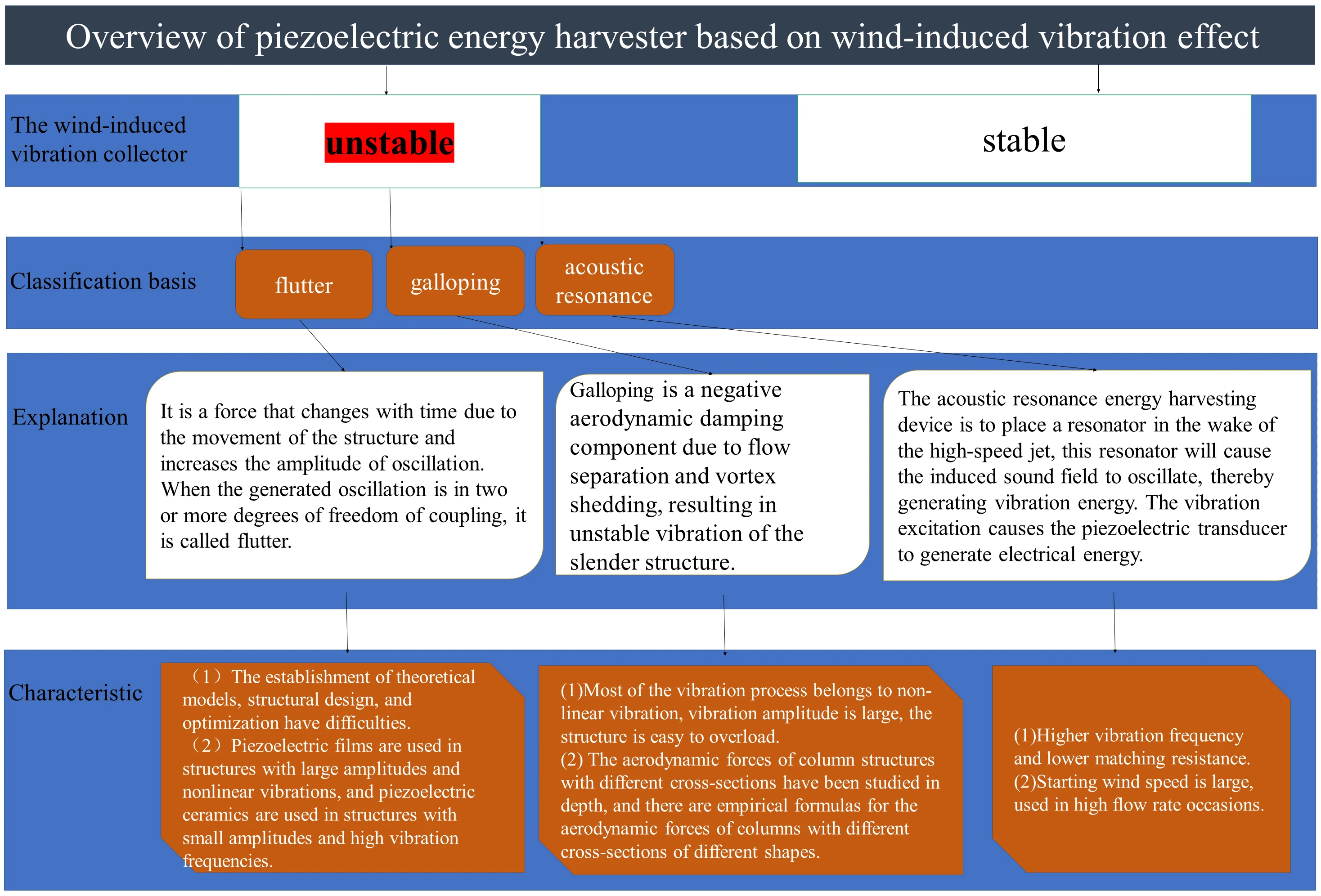
The wind-induced vibration effect is essentially a process of fluid-solid coupling in which the kinetic energy of the fluid and the vibration energy of the solid are converted into each other. The conversion process from wind to vibration can be divided into stable and unstable according to the dynamic mechanism of fluid mechanics [4]. This article mainly analyzes the unstable flow, which can be subdivided into three types: flutter, galloping, and acoustic resonance [5]. The following will analyze the basic principles and related theories of these effects, and then analyze some typical structures and cases.
2.1. Analysis of research status of flutter-type harvesting device
Flutter is an unstable type. It is a force that changes with time due to the movement of the structure and increases the amplitude of oscillation. When the generated oscillation is in two or more degrees of freedom of coupling, it is called flutter [6], [7]. As far as the current research status is concerned, flutter-based wind-induced vibration energy harvesters mainly include two major categories: flexible structures and elastically supported rigid structures.
2.1.1. Analysis of the research status of flexible energy harvesting devices
For flutter energy collectors with flexible structures, mainly flexible films and flexible bands, most piezoelectric materials are PVDF. For example, in 2006, Robbins of the University of Minnesota in the United States connected the PVDF piezoelectric film to the bluff body. When the flexible piezoelectric film is blown by the airflow, it flutters in the wind like a flag, making the piezoelectric film bending and vibration and thus generate electricity [8]. The experiment measured that when the wind speed reaches 6.7 m/s, the maximum open circuit voltage reaches 40 V, and the maximum output power is 1 mW at the optimal load is 250kΩ. In 2010, Akaydin et al. installed the flexible PVDF piezoelectric film in the vortex street behind the cylinder, but the free end is in front and the fixed end is behind[9]. The experimental results show that when the air velocity is 7.23 m/s, the output power at 7.23 m/s can reach 4 μW. In 2011, Shuguang Li et al. of Northwestern Polytechnical University and Cornell University in the United States hinged a triangular blade at the free end of a flexible PVDF membrane, which stimulated branch vibration by imitating the vibration of leaves in the wind [9], where the PVDF piezoelectric film is equivalent to the branches of the tree, the maximum output power measured by the experiment at the optimal load reaches 0.6 mW. A flexible beam micro piezoelectric wind energy harvesting device with resonant cavity was designed by Zhigang Du and Xuefeng He from Chongqing University in 2012 [10]. The device consists of an open resonant cavity and a flexible beam obliquely oriented to the direction of the incoming flow, and the experiment measured that when the wind speed reaches 17m/s, the maximum output power is 1.31 mW. In 2012, Kiran Singh of France designed a double-articulated cylindrical piezoelectric energy harvesting device [11]. As shown in Fig. 1, it has been shown that the flow rate is the main factor affecting the generation of unstable fluids. The viscous buffer should be kept away from the driving Stable region, and a nonlinear reduced-order model of a two-degree-of-freedom cylindrical system. In 2015, M. Perez et al. took fluttered flexible membranes and developed an electret-based aeroelastic flutter energy harvester through an electrostatic conversion mechanism [12] and developed an electret-based aeroelastic flutter energy harvester. It uses the flutter effect combined with electret-based conversion to convert the motion caused by the flow of the membrane into electrical energy. The proposed device consists of two parallel plane electrodes covered with a 25 μm polymer film, and a baffle is placed at the entrance of the device to cause the vortex to fall off. When any type of wind or air flow flows through the collection device, the membrane enters an oscillating state due to fluttering and continuously contacts two fixed electrodes coated with Teflon. Due to the electret-based conversion process, this periodic motion is directly converted into electricity, and experimentally measured when the wind speed is 30 m/s, the output power can reach 2.1mw. In 2019, Xiaobiao Shan et al. of the Harbin Institute of Technology developed a flutter-based energy harvesting device for curved plates [13]. As shown in Fig. 2. The flow electromechanical equivalent model of the energy collection device was established, and the wind was designed. The results of the hole experiment show that the energy harvesting effect of the segmented piezoelectric sheet is better than that of the continuous sheet, and the continuous output power density of the airflow velocity at 25 m/s was 0.032 mW/cm3.
Fei Fei et al. from the Chinese University of Hong Kong gave an empirical formula [14] for the cut-in speed when flutter occurs, which can be expressed as:
where is the radius of gyration of the cross-section, is the mass per unit length, is the width of the structure, is the fluid density, and and are the angular frequencies in the rotation and translation directions. Due to the low electromechanical conversion efficiency of PVDF piezoelectric thin film.
Fig. 1Kiran Singh et al. developed a double-hinge cylindrical transducer [11]
![Kiran Singh et al. developed a double-hinge cylindrical transducer [11]](https://static-01.extrica.com/articles/23421/23421-img1.jpg)
Fig. 2Xiaobiao Shan et al curved plate developed energy harvesting device [13]
![Xiaobiao Shan et al curved plate developed energy harvesting device [13]](https://static-01.extrica.com/articles/23421/23421-img2.jpg)
2.1.2. Analysis of the research status of energy harvesting devices with rigid structures
For a flutter-type energy harvesting device with an elastically supported rigid structure, hydrodynamic forces can be viewed as a function of the lateral displacement of the rigid body, the velocity, and the torsional angle and torsional angular velocity [15]. Due to its simple structure, there are many research papers on the vibration energy collection of rigid structures with elastic supports. For example, in 2009, Pobering of the Munich University of Science and Technology installed the PZT piezoelectric bimorph behind a rectangular column to form an array[16], as shown in Fig. 3. The size of the PZT piezoelectric bimorph is 12 mm×11.8 mm×0.35 mm. At a wind speed of 45 m/s, the output voltage is 0.8 V, and the maximum output power was 0.1 mW. In 2010, Hobbs of the Georgia Institute of Technology in the United States processed a wind-induced vibration structure [17]. The multi-column supported by elastic rubber rods in the wind itself Vortex-induced vibration occurs, and a piezoelectric transducer is installed at the root of the rubber rod with the largest strain to convert wind energy into electrical energy. The output power was 96 μW at wind speeds of 1-3 m/s. In 2010, Clair et al. of Clemson University in the United States imitated the vibration mechanism of the reed in the harmonica and proposed a fluid energy collection device [18]. The cantilever beam excitation piezoelectric transducer device, when the fluid enters the cavity, the pressure inside the cavity rises, causing the cantilever beam at the end of the cavity to bend under the force and release the pressure inside the cavity, so that the cantilever beam can be bounced back under the action of the restoring force and close the cavity into the next cycle. By attaching piezoelectric material to the cantilever beam, the reciprocating vibration energy of the cantilever beam can be converted into electrical energy. In 2011, Bryant et al. at Cornell University in the United States used a wing structure at the free end of the PZT piezoelectric cantilever beam to collect wind energy [19]. The flutter of the wing caused the piezoelectric beam to vibrate together. At a wind speed of 8 m/s, the output is 2.2 mW. In 2012, Weinstein of the Department of Mechanical Engineering of Berkeley, California, USA placed the PZT piezoelectric sheet in the vortex street behind the cylinder and installed a blade at the free end of the PZT beam [20], as shown in Fig. 4. The output power is 3 mW at a wind speed of 5 m/s, but the overall size of the device is large. In 2014, Virginia Tech and HL Dai of Huazhong University of Science and Technology developed a piezoelectric energy collector [21]. The collection device consists of a multilayer piezoelectric cantilever beam, and the cylindrical tip mass is connected to its free end. The free end is Placed in a uniform airflow and subject to direct harmonic excitation. When the wind speed is in the pre-synchronization or post-synchronization area, its associated electromechanical damping increases, thus obtaining a reduction in the collected power. When the wind speed is in the locked or synchronized area, the results show that compared with the use of two separate energy harvesting devices, the harvest power level is significantly improved [22]. When the wind speed reaches 22 m/s, the maximum power reaches 1.2 mW. In 2016, Huazhong University of Science and Technology and Singapore’s Nanyang Technological University’s HL Dai et al. studied the bluff body positioning technique for designing an efficient energy harvester from vortex-induced vibration [23], and derived different bluff body positioning schemes for different wind speeds. For small wind speeds between 1.3-1.8 m/s, the top configuration (case 2) is the best choice. For higher wind speeds of 3-4.4 m/s, the vertical configuration should be used (Case 4). If the wind speed increases (for example, 10-20 m/s), the VIV energy should be redesigned the harvesters to increase the shedding frequency and natural frequency of these harvesters, thereby achieving resonance with the system. In 2018, Guilherme R. Franzini et al. from the University of Sao Paulo in Brazil conducted a numerical study to obtain piezoelectric energy from vortex-induced vibrations of one degree of freedom and two degrees of freedom [24] and finally proved a two-degree-of-freedom vortex-induced vibration energy harvesting device. The efficiency is significantly improved compared to the one-degree-of-freedom vortex-induced vibration energy collection, which proves that the energy collection efficiency of the flutter energy collector is higher than that of the gallop-type energy collection.
Fig. 3Piezoelectric sensor arrays designed by Pobering et al. [16]
![Piezoelectric sensor arrays designed by Pobering et al. [16]](https://static-01.extrica.com/articles/23421/23421-img3.jpg)
Fig. 4Weinstein et al developed turbulent vortex-induced vibration energy harvesting devices [20]
![Weinstein et al developed turbulent vortex-induced vibration energy harvesting devices [20]](https://static-01.extrica.com/articles/23421/23421-img4.jpg)
From the above research, it can be found that due to the different piezoelectric materials of the transducing piezoelectric energy collector, the rigid structure has higher collection efficiency than the flexible structure, but the rigid structure has a larger size than the flexible structure. There is no universal theoretical formula for the determination of aerodynamic forces. The establishment of theoretical models, structural design, and optimization are difficult. Research on rigid structures has progressed rapidly, and the lift, torque, and attack of aerodynamic forces during the coupling process have been obtained. The empirical formula of angle can be expressed as [15]:
where is the aerodynamic lift, is the torque; is the effective angle of attack, is the fluid density, is the flow rate, is the half-chord length, is the lift coefficient, is the torque coefficient, is the nonlinear parameter related to stall, a is the offset of the elastic axis relative to the half-chord, h is the lateral displacement, is the rotation angle.
Table 1Statistics of input and output parameters of flutter energy collector
Researcher | Vibration frequency (Hz) | Materials | Fluid velocity (m/s) | Output Power (mW) | Matching resistance (KΩ) | Power density (mW/cm3) |
Robbins | 5 | PVDF | 6.7 | 10 | 250 | |
Pobering | 600 | PZT | 45 | 0.1 | 1.2 | 0.256 |
Hobbs | 20 | PZT | 1--3 | 0.096 | 1×10⁶ | |
Akaydin | 48.4 | PVDF | 7.23 | 0.004 | 1×10⁶ | |
D. St. Clair | 84 | PZT | 12.5 | 0.8 | 49.65 | 0.02 |
Shuguang Li | PVDF | 4 | 0.6 | 30×106 | 2 | |
Bryant | 16 | PZT | 8 | 2.2 | ||
Weinstein | 16-40 | PZT | 5 | 3 | 22 ×106 | |
Kiran Singh | PVDF | 2.65 | 5.6 | |||
H. L. Dai | 4 | PZT | 22 | 1.2 | 2.46 ×10⁶ | |
M Perez | 156 | PTFE | 15 | 2.1 | 14 ×106 | 0.782 |
Guilherme R. Franzini | 0.62 | PZT | Relative velocity 5 | 11 | 100 | |
Xiaobiao Shan | 17.2 | PVDF | 20 | 0.26 | 10 ×106 | 0.032 |
It can be seen from Table 1 that the power density of the piezoelectric transducer is directly related to the vibration frequency. The power density with a large frequency is relatively high, and the piezoelectric constant of the PVDF piezoelectric film is low. At present, the PVDF piezoelectric film is mainly used in amplitude among the large transducers that involve nonlinear vibration. PZT piezoelectric ceramics have large piezoelectric constants but are easily broken and rupture, and are suitable for transducers with small amplitudes. At the same time, they have found opportunities for flexible structures of PVDF piezoelectric thin films. There is no universal theoretical formula for the determination of aerodynamic forces. The establishment of theoretical models, structural design, and optimization have difficulties [25]-[28]. The rigid structure based on PZT piezoelectric ceramics has obtained an aerodynamic empirical formula, but little research has been reported on the fatigue properties of the structures.
2.2. Research status analysis of galloping energy harvesting device
Galloping is a negative aerodynamic damping component due to flow separation and vortex shedding, resulting in unstable vibration of the slender structure [2]. Studies have shown that the hydrodynamic force of galloping is mainly related to the relative velocity of the fluid to the structure and the angle of attack of the fluid to the structure [15], and its empirical formula can be expressed as:
where is aerodynamic force, is the fluid density; is the structural size of the windward surface of the cylinder, and are the coefficients related to the cross-sectional shape of the cylinder, generally obtained through experiments.
Because the structure of the gallop-type wind-induced vibration energy collection device is simpler, the research based on the gallop-type wind-induced vibration energy collection device has made relatively great progress. For example, in 2012, Jayant Sirohi et al. in the United States developed a cantilever beam wind energy collection device with bimorphs using the galloping effect [29] and experimentally measured the maximum energy at a wind speed of 4.7 m/s and a vibration frequency of 4.167 Hz. In 2013, Abdessattar Abdelkefi et al. studied gallop-based piezoelectric energy harvesting devices with different cross-sectional geometries [30]. The results showed that the geometry of the electronic load and the cross-section have a significant effect on the start-up speed of galloping. The flow rate at the optimal energy harvesting state corresponding to the cross-sectional shape is very different. In 2015, Liya Zhao et al. of Nanyang Technological University added reinforcement ribs to the cantilever beam [31]. As shown in Fig. 5, the purpose is to expand the effective wind speed range, thereby increasing the vibration energy generated in the effective wind speed range. Compared with the traditional design without ribs, it has superior performance, and the power has been increased dozens of times. The experiment measured that the maximum output power reached 139.74 mW when the wind speed was 15 m/s, which was higher than most of the energy harvesting devices, but no analysis of the fatigue strength of the beam. In 2016, Amitabh Bhattacharya et al. in India studied an energy harvesting device for the torsional oscillation of an elliptical cylinder [32]. Through simulation and theoretical calculations, the energy conversion efficiency reached 0.8 % when the Reynolds number was 100. When the Reynolds number was 200 the energy conversion efficiency reached 1.7 %. Abdessattar Abdelkefid et al. determined the best vibration mode of beam prismatic structure through modal analysis, and established a nonlinear distributed parameter model to determine the influence of load resistance and wind speed on the energy harvesting power of the energy harvester [33]. Finally, it is demonstrated that the efficiency of the two-degree-of-freedom vortex-excited vibration energy harvesting device is significantly improved compared to the one-degree-of-freedom vortex-excited vibration energy harvesting, and it is confirmed that the energy harvesting efficiency of the flutter energy harvester is higher than that of the galloping type energy harvesting efficiency In 2018, Felix Ewere et al. in the United States studied the experimental performance of piezoelectric energy harvesting devices based on the galloping effect [34]. The results show that once the shape of the bluff body is determined, the size of the critical velocity will depend on the length of the bluff body span with the system damping. Experimentally measured that when the flow rate of the piezoelectric energy harvesting device is 10.5 m/s, the maximum output power of electrical energy is 1.75 mW, and the vibration frequency of the piezoelectric beam is 20 Hz. In 2019, Iran’s S. Sobhanirad et al. studied the optimal choice of bluff body cross-sections at different wind speeds [35]. At low speeds, the triangular cross-section fluid is the optimal choice for energy harvesting systems. The vibration of the D-shaped cross-section bluff body suddenly increases at higher flow rates, while the vibration amplitude of the square and triangular geometry increases uniformly with the increase of wind speed. It is concluded that the triangular cross-section is the most suitable energy harvesting system for the actual situation. In 2019, Wang Junlei et al. studied the apex angle of different equilateral isosceles triangle cross-sections on the galloping wind-induced vibration energy harvester [36]. As shown in Fig. 6, the apex angle was less than 20° through experiments and simulations. When the apex angle is greater than 140°, it is not sensitive to wind speed. The phenomenon of galloping between 20° and 140° is obvious, and it proves that 130° is the optimal choice for the apex angle.
Fig. 5Structure designed by Liya Zhao [31]
![Structure designed by Liya Zhao [31]](https://static-01.extrica.com/articles/23421/23421-img5.jpg)
Fig. 6Structure designed by Wang Junlei et al. [36]
![Structure designed by Wang Junlei et al. [36]](https://static-01.extrica.com/articles/23421/23421-img6.jpg)
Table 2Statistics on input and output parameters of gallop-type energy collector
Researcher | Vibration frequency (Hz) | Materials | Fluid velocity (m/s) | Output power (mW) | Matching resistance (KΩ) | Power density (mW/cm3) |
Jayant Sirohi | 4.167 | PZT | 4.7 | 1.14 | 0.8×10⁶ | |
Liya Zhao | PZT | 15 | 139.74 | 13.47 | ||
Felix Ewere | 20 | MFC-M0714 | 10.5 | 1.74 | 500 | 2.28 |
Wang Junlei | 9.6 | MFC-M2807 | 5 | 105 |
Studies have collected galloping-type apparatus for a certain understanding of energy, especially in the study of aerodynamic pillar structure in different sections of further comparison. The empirical formula for the aerodynamic cross-sectional shape of the different columns has a corresponding structure, especially for D-shaped structures, triangular structures, and elliptical structures. The vibration frequency of the gallop-type energy harvesting device is generally low, the flow velocity width is not more than 50 m/s, and the vibration process is mostly nonlinear vibration [37]-[40], the vibration amplitude is large, and the structure is prone to overload. From the above research, it is found that the gallop-type energy collection device has a small structure and high energy conversion efficiency. The vibration frequency of the elastic body is lower than the vortex shedding frequency of the Carmen vortex street. The cantilever beam deformation is large and most of the vibration modes are nonlinear vibration. However, there is still a lack of reliability research on gallop-type energy harvesting devices.
2.3. Research status of acoustic resonance energy harvesting device
The principle of the acoustic resonance energy harvesting device is to place a resonator in the wake of the high-speed jet, this resonator will cause the induced sound field to oscillate, thereby generating vibration energy. The vibration excitation causes the piezoelectric transducer to generate electrical energy. The resonator is the resonant cavity. The acoustic modal frequency of the resonant cavity is a very important parameter, which directly affects the power generation of the generator. Existing studies have shown that the size of the acoustic modal frequency in the resonant cavity is mainly related to the resonant cavity. The length, diameter, and distance from the resonance cavity to the air outlet are related [41]-[47], the existing empirical formula can be expressed as:
where and are the depth and diameter of the cavity respectively, and is a constant related to the experiment.
Research on acoustic resonance energy harvesting devices is active. The earliest Harry Diamond invented the airflow resonant generator in 1960, also known as the jet generator [48]-[50], which is used as a fuze power supply. As early as 1999, Yang Yichun et al. from Nanjing University of Science and Technology proposed a fuze power source using air vibration [51] and carried out a simple theoretical study on it. Finally, an AC vibration voltage with a frequency of 100-250 Hz was obtained through simulation experiments. The output voltage reaches 30 V at a flight speed of 60 m/s, and the simulated voltage reaches 100 V at a flight speed of 100 m/s, but he did not conduct a detailed study of the output power. In 2006, Dr. Li Yingping of Nanjing University of Science and Technology proposed an airflow resonance piezoelectric generator using the piezoelectric effect [52]. Based on the jet generator, the connecting rod, the tongue spring, and the electromagnetic component were omitted, and the piezoelectric transducer device was changed. In 2009, Seong-Hyok Kim et al. designed a generator based on the Helmholtz resonator [53]. The experiment measured that when the input pressure is 50 kPa, it can generate a peak voltage of 81 mV, the vibration frequency is 0.53 kHz, and the measured wind speed is 5 m/s. In 2009, Lei Junming et al. from Xi’an Electromechanical Research Institute successfully designed a 34 mm-diameter air-flow resonant piezoelectric generator[54], which uses a piezoelectric film PVDF as a piezoelectric vibrator, and simply studied the resonance characteristics of the piezoelectric vibrator. A simple experimental study was conducted on the open circuit voltage output by the generator. The experiment measured that when the flow velocity 300 m/s, the vibration frequency is about 1.2 kHz, the generator output voltage is 39.5 V, the output power is close to 1.6 W, and the matching resistance is 1 kΩ, which proves that the airflow resonance generator is suitable for low power fuze. In 2012, Wang Jiu, Xu Wei, et al. designed a fuze micro-electromechanical airflow excitation power supply based on the principle of piezoelectric power generation [55], which was verified to be feasible at an inlet airflow velocity of 50-300 m/s, but due to MEMS technology is not mature enough, and no finished product has been designed. In 2012, Du Zhigang et al. designed a microwind generator based on a resonant cavity [56]. As shown in Fig. 7, the lengths of piezoelectric beams and flexible beams were studied through experiments. The experiments proved that when the wind speed is 17 m/s, the generator is 250 KΩ. The output power of the load resistance is 1.31 mW, the power density is about 66 μW/cm3. In 2015, Chen Hejuan from Nanjing University of Science and Technology successfully designed an air-flow resonance piezoelectric generator with an annular gap structure [56]. As shown in Fig. 8, the piezoelectric ceramic material PZT-5H was used. At a flow velocity of 159 m/s, the vibration frequency of the electric vibrator is 6-7 kHz, the effective value of the open circuit voltage reaches 22 V, the matching resistance is 4KΩ, and the output power reaches 58 mW. At the same time, Chen Hejuan successfully designed a central column airflow resonance piezoelectric generator [57], piezoelectric materials The piezoelectric ceramic PZT-5H is also used. When the flow velocity is 152 m/s, the oscillation frequency is about 3.5 kHz, and the peak voltage is 49.9 V at a flow velocity of 200 m/s.
Fig. 7Designed by Du Zhigang [56]
![Designed by Du Zhigang [56]](https://static-01.extrica.com/articles/23421/23421-img7.jpg)
Fig. 8Designed by Chen Hejuan [57]
![Designed by Chen Hejuan [57]](https://static-01.extrica.com/articles/23421/23421-img8.jpg)
It can be found from the table that the energy density of acoustic resonance energy harvesting devices is larger than that of flutter and gallop types. The acoustic resonance energy harvesting structure has a higher vibration frequency, lower matching resistance, higher output power, and higher inflow velocity. It is generally based on simulation experiments and is mostly used in high-wind speed environments, such as ammunition fuzes.
Table 3Statistics of input and output parameters of resonance energy collector
Researcher | Vibration frequency (Hz) | Materials | Fluid velocity (m/s) | Output power (mW) | Matching resistance (KΩ) | Power density (mW/cm3) |
Yang Yichun | 100-250 | PZT | 100 | |||
Lei Junming | 1.2×10³ | PVDF | 300 | 1.6×10³ | 1 | 440 |
Du Zhigang | 137 | PVDF | 17 | 1.31 | 250 | 0.066 |
Chen Hejuan | 6-7×10³ | PZT-5H | 159 | 58 | 4 | 512 |
2.4. Research status of other wind-induced vibration energy harvesting devices
The above-mentioned wind-induced vibration energy uses vortex-induced vibration to directly or indirectly cause the air medium to oscillate. There are many other wind-induced vibration energy collection devices, such as frictional wind power generation, windmill-type energy collection devices, and road surface energy collection devices. In 2019, Martin Olsen et al. in Switzerland developed a friction nano-piezoelectric generator [58]. The principle is to place a piezoelectric film in a wind tunnel. under the action of wind, the piezoelectric film vibrates between two copper electrodes. It is experimentally measured that the electric energy generated when the wind speed is 1.6 m/s is enough to light an LED lamp, and it is found that as the wind speed increases from 0-8 m/s, the vibration frequency also increases linearly. In 2018, Chan Ho Yang et al. in South Korea proposed a small windmill-type piezoelectric energy collector [59]. As shown in Fig. 10, when the wind speed is 1.94 m/s, the power generation frequency is 10.25 Hz, and the maximum output power of the windmill is 3.14 mW. The road energy collection device mainly uses the vibration of the vehicle passing through the road [60], and directly uses the tire pressure to collect energy [61], and the design of piezoelectric shoes for piezoelectric energy collection [62], etc.
Fig. 9Designed by Martin Olsen [58]
![Designed by Martin Olsen [58]](https://static-01.extrica.com/articles/23421/23421-img9.jpg)
Fig. 10Designed by Chan Ho Yang [59]
![Designed by Chan Ho Yang [59]](https://static-01.extrica.com/articles/23421/23421-img10.jpg)
The friction-type wind-induced vibration energy collection device has a small structure, which is convenient for miniaturization, but the reliability of the structure is poor, and the energy conversion rate is low. The windmill-type piezoelectric energy collection device has high power generation efficiency, but the general structure is large, and the moving parts are relatively small. The moving parts are repeatedly impacted and rubbed, which is easy to cause parts to fail and the wiring is more complicated. The structure of the road energy harvesting device is larger than that of the windmill-type energy harvesting device, and the sensitivity to the road vibration is low, resulting in low power generation efficiency, high cost, and difficult maintenance.
3. Conclusions
The structural characteristics and main parameters of the above different wind-induced vibration energy collection devices are summarized in the following table. According to the different mechanisms of the wind-induced vibration effect, the input and output conditions of different types of energy collectors are analyzed and summarized in Table 4.
Table 4Statistics of input and output parameters of wind-induced vibration energy collector
Researcher | Vibration frequency (Hz) | Materials | Fluid velocity (m/s) | Output power (mW) | Matching resistance (KΩ) | Power density (mW/cm3) |
Flutter | <200 | PVDF | <50 | <10 | 20-10×106 | <2 |
Galloping | <50 | PZT | <20 | <139.74 | 100-0.8×10⁶ | <13.47 |
Resonant cavity | <10×103 | PVDF and PZT | <300 | <1.6×10³ | 1-250 | <512 |
others | <50 | PVDF | <20 | <10 |
By analyzing the input and input parameters of the wind-induced vibration energy collector, it is summarized as follows:
1) The flow rate is low. In addition to the acoustic resonance type energy harvesting device, the inflow velocity of other wind-induced vibration energy harvesting devices is generally lower than 20 m/s.
2) The frequency is low. Except for the acoustic resonance type energy harvesting device, the wind-induced vibration energy is generally lower than 500 Hz. However, according to the empirical formula , it can be seen that when the frequency increases, the internal resistance of the piezoelectric generator can be significantly reduced, which has a significant effect on the improvement of the output power. From the perspective of improving energy conversion efficiency, cavity-type energy collection devices have great advantages.
3) Low output power. At present, the output power of the piezoelectric energy harvesting device as a whole is very low, basically less than 10 mW, and they are all used for micropower consumption devices. The energy density is generally less than 1 mw/cm3, and it is difficult to balance the relationship between volume and energy output.
4) Poor reliability. At present, all kinds of piezoelectric energy harvesting devices have this problem. Among them, chattering and galloping energy harvesting devices are prone to mechanical overload of auxiliary structures, and resonant cavity energy harvesting devices are prone to cause the breakage of piezoelectric vibrators themselves.
5) Poor adaptability to the working environment. Flutter and gallop-type energy collection devices have strict requirements on the direction and velocity of the airflow. The direction of flow and a certain range of flow rate must be formulated to generate vibration energy. Although the acoustic resonance type energy collector can perform inflow modulation, it also has It can only modulate the incoming flow within a certain range.
Comprehensively analyze the research status and development trend of the piezoelectric energy collector based on wind vibration effect at home and abroad, and find that the conversion process from wind energy to vibration energy is mainly dominated by vibratory vibration, chirp vibration, and resonance cavity-type wind vibration energy, and the conversion process from vibration energy to electric energy is dominated by piezoelectricity, supplemented by magnetoelectricity and friction power generation, and for the places of high power density and high power generation energy, the resonance cavity-type wind vibration energy collector is the main development trend. Energy collection is the main development trend.
References
-
Renwen Chen, “New environmental energy harvesting technology,” (in Chinese), National Defense Industry Press, 2021.
-
A. Abdelkefi, “Aeroelastic energy harvesting: A review,” International Journal of Engineering Science, Vol. 100, pp. 112–135, Mar. 2016, https://doi.org/10.1016/j.ijengsci.2015.10.006
-
Dakai Lin, Acoustic Control of Turbulent Jets. (in Chinese), Beijing: Aviation Industry Press, 2018.
-
F. Zhang and L. Wang, Modern Piezoelectrics. (in Chinese), Beijing: Science Press.
-
S. Wei, “Research on the characteristics and application of piezoelectric ceramic power generation,” (in Chinese), Dalian University of Technology, Dalian, 2007.
-
A. B. Rostami and M. Armandei, “Renewable energy harvesting by vortex-induced motions: review and benchmarking of technologies,” Renewable and Sustainable Energy Reviews, Vol. 70, pp. 193–214, Apr. 2017, https://doi.org/10.1016/j.rser.2016.11.202
-
S. Li, J. Yuan, and H. Lipson, “Ambient wind energy harvesting using cross-flow fluttering,” Journal of Applied Physics, Vol. 109, No. 2, Jan. 2011, https://doi.org/10.1063/1.3525045
-
William P. Robbins, Dustin Morris, Ivan Marusic, and Todd O. Novak, “Wind-generated electrical energy using flexible piezoelectric materials,” in 2006 ASME International Mechanical Engineering Congress and Exposition, IMECE2006, pp. 1–9, 2006.
-
H. D. Akaydın, N. Elvin, and Y. Andreopoulos, “Wake of a cylinder: a paradigm for energy harvesting with piezoelectric materials,” Experiments in Fluids, Vol. 49, No. 1, pp. 291–304, Apr. 2010, https://doi.org/10.1007/s00348-010-0871-7
-
Z. Du, “Research on micro wind turbine based on resonant cavity structure,” (in Chinese), Chongqing University, 2012.
-
K. Singh, S. Michelin, and E. de Langre, “Energy harvesting from axial fluid-elastic instabilities of a cylinder,” Journal of Fluids and Structures, Vol. 30, pp. 159–172, Apr. 2012, https://doi.org/10.1016/j.jfluidstructs.2012.01.008
-
M. Perez, S. Boisseau, P. Gasnier, J. Willemin, and J. L. Reboud, “An electret-based aeroelastic flutter energy harvester,” Smart Materials and Structures, Vol. 24, No. 3, p. 035004, Mar. 2015, https://doi.org/10.1088/0964-1726/24/3/035004
-
X. Shan, H. Tian, D. Chen, and T. Xie, “A curved panel energy harvester for aeroelastic vibration,” Applied Energy, Vol. 249, pp. 58–66, Sep. 2019, https://doi.org/10.1016/j.apenergy.2019.04.153
-
F. Fei and W. J. Li, “A fluttering-to-electrical energy transduction system for consumer electronics applications,” in 2009 IEEE International Conference on Robotics and Biomimetics (ROBIO), pp. 580–585, Dec. 2009, https://doi.org/10.1109/robio.2009.5420607
-
X. Zhao, J. Wang, and J. Cai, “Research status of miniature wind energy collector based on wind-induced vibration effect,” (in Chinese), Vibration and shock, No. 16, 2017.
-
S. Pobering, S. Ebermeyer, and N. Schwesinger, “Generation of electrical energy using short piezoelectric cantilevers in flowing media,” in SPIE Smart Structures and Materials + Nondestructive Evaluation and Health Monitoring, Vol. 7288, pp. 109–116, Mar. 2009, https://doi.org/10.1117/12.815189
-
W. B. Hobbs, “Piezoelectric energy harvesting: vortex induced vibrations in plants, soap films, and arrays of cylinders,” Georgia Institute of Technology, Atlanta, USA, 2010.
-
D. St. Clair, A. Bibo, V. R. Sennakesavababu, M. F. Daqaq, and G. Li, “A scalable concept for micropower generation using flow-induced self-excited oscillations,” Applied Physics Letters, Vol. 96, No. 14, Apr. 2010, https://doi.org/10.1063/1.3385780
-
M. Bryant, E. Wolff, and E. Garcia, “Aeroelastic flutter energy harvester design: the sensitivity of the driving instability to system parameters,” Smart Materials and Structures, Vol. 20, No. 12, p. 125017, Dec. 2011, https://doi.org/10.1088/0964-1726/20/12/125017
-
L. A. Weinstein, M. R. Cacan, P. M. So, and P. K. Wright, “Vortex shedding induced energy harvesting from piezoelectric materials in heating, ventilation and air conditioning flows,” Smart Materials and Structures, Vol. 21, No. 4, p. 045003, Apr. 2012, https://doi.org/10.1088/0964-1726/21/4/045003
-
H. L. Dai, A. Abdelkefi, and L. Wang, “Piezoelectric energy harvesting from concurrent vortex-induced vibrations and base excitations,” Nonlinear Dynamics, Vol. 77, No. 3, pp. 967–981, Mar. 2014, https://doi.org/10.1007/s11071-014-1355-8
-
Liu Song and Fu Song. The Phenomenon Of, “The phenomenon of "locking" of the frequency of bluff body oscillation in uniform flow,” (in Chinese), in Proceedings of the 10th National Computational Fluid Mechanics Conference, 2000.
-
H. L. Dai, A. Abdelkefi, Y. Yang, and L. Wang, “Orientation of bluff body for designing efficient energy harvesters from vortex-induced vibrations,” Applied Physics Letters, Vol. 108, No. 5, Feb. 2016, https://doi.org/10.1063/1.4941546
-
G. R. Franzini and L. O. Bunzel, “A numerical investigation on piezoelectric energy harvesting from Vortex-Induced Vibrations with one and two degrees of freedom,” Journal of Fluids and Structures, Vol. 77, pp. 196–212, Feb. 2018, https://doi.org/10.1016/j.jfluidstructs.2017.12.007
-
H. Chen, “Research on output characteristics of time-averaged shock engine based on PZT transducer,” (in Chinese), Zhejiang University, 2013.
-
J. Pan et al., “Energy harvesting based on piezoelectric effect,” Piezoelectric and acousto-optic, Vol. 3, No. 3, pp. 54–56, 2009.
-
J. Shi, G. Gao, and R. Teng, “Research on piezoelectric energy harvesting monitoring device of shearer state with adaptive excitation frequency,” (in Chinese), Journal of Sensing Technology, Vol. 31, No. 15, pp. 31–35, 2018.
-
D. Sun, Y. Xu, H. Chen, and W. Qu, “Experimental study of time-averaged current excited acoustic engine: the influence of the geometry of the resonance tube nozzle,” (in Chinese), Journal of Engineering Thermophysics, Vol. 34, No. 12, pp. 2208–2211, 2013.
-
R. R. Mahadik and J. Sirohi, “Harvesting wind energy using a galloping piezoelectric beam,” in ASME 2009 Conference on Smart Materials, Adaptive Structures and Intelligent Systems, Jan. 2009, https://doi.org/10.1115/smasis2009-1479
-
A. Abdelkefi and A. O. Nuhait, “Modeling and performance analysis of cambered wing-based piezoaeroelastic energy harvesters,” Smart Materials and Structures, Vol. 22, No. 9, p. 095029, Sep. 2013, https://doi.org/10.1088/0964-1726/22/9/095029
-
L. Zhao and J. Ng, “Enhancement of aeroelastic energy harvesting from galloping, vortex-induced vibrations and flutter with a beam stiffener,” Unpublished, Vol. 24, No. 3, Jan. 2014, https://doi.org/10.13140/2.1.4450.6404
-
A. Bhattacharya and S. S. S. Shahajhan, “Power extraction from vortex-induced angular oscillations of elliptical cylinder,” Journal of Fluids and Structures, Vol. 63, pp. 140–154, May 2016, https://doi.org/10.1016/j.jfluidstructs.2016.03.008
-
A. Abdelkefi, Z. Yan, and M. R. Hajj, “Performance analysis of galloping-based piezoaeroelastic energy harvesters with different cross-section geometries,” Journal of Intelligent Material Systems and Structures, Vol. 25, No. 2, pp. 246–256, Jun. 2013, https://doi.org/10.1177/1045389x13491019
-
F. Ewere, G. Wang, and A. Frendi, “Experimental investigation of a bioinspired bluff-body effect on galloping piezoelectric energy-harvester performance,” AIAA Journal, Vol. 56, No. 3, pp. 1284–1287, Mar. 2018, https://doi.org/10.2514/1.j056152
-
S. Sobhanirad and A. Afsharfard, “Improving application of galloping-based energy harvesters in realistic condition,” Archive of Applied Mechanics, Vol. 89, No. 2, pp. 313–328, Sep. 2018, https://doi.org/10.1007/s00419-018-1469-4
-
J. Wang, L. Tang, L. Zhao, and Z. Zhang, “Efficiency investigation on energy harvesting from airflows in HVAC system based on galloping of isosceles triangle sectioned bluff bodies,” Energy, Vol. 172, pp. 1066–1078, Apr. 2019, https://doi.org/10.1016/j.energy.2019.02.002
-
W. Jiang, “Analytical, numerical and experimental studies on the nonlinear energy harvester,” (in Chinese), Shanghai University, 2016.
-
H. Qiao, “Research on vibration characteristics and energy harvesting of nonlinear piezoelectric cantilever,” (in Chinese), Tianjin University, 2016.
-
Y. Gao et al., “Research on vibration response and energy harvesting of elastically supported double stabilized electric cantilever beam,” (in Chinese), Physics, Vol. 2014, No. 9, pp. 62–74, 2014.
-
H. Xue, “Analysis and optimization of nonlinear dynamic behavior of piezoelectric energy harvesting/energy storage system,” (in Chinese), Huazhong University of Science and Technology, 2008.
-
A. B. Cain and E. J. Kerschen, “Simulation of power resonance tubes effects of pressure ratio and freestream,” AIAA Paper, Jun. 2002.
-
J. Kastner and M. Samimy, “Development and characterization of Hartmann tube based fluidic actuators for high-speed flow control,” 40th AIAA Aerospace Sciences Meeting and Exhibit, Jan. 2002, https://doi.org/10.2514/6.2002-128
-
A. Hamed, K. Das, and D. Basu, “Numerical simulation and parametric study of Hartmann-Sprenger tube based powered device,” 41st Aerospace Sciences Meeting and Exhibit, Jan. 2003, https://doi.org/10.2514/6.2003-550
-
B. Lu, “Hartman acoustic sounder acoustic propagation characteristics and application research,” (in Chinese), Journal of University of Petroleum (Natural Science Edition), Vol. 28, No. 6, pp. 123–125, 2004.
-
L. Zhang, Z. Tian, and X. Zeng, “Analysis of determinants of resonance frequency of Hartmann resonance,” (in Chinese), Acoustic Technology, Vol. 27, No. 5, pp. 212–213, 2008.
-
H. Zou, H. Chen, and X. Zhu, “Characterization of acoustic excited power resonance tube for on-board piezoelectric generator,” in the 5th International Conference on Material Engineering and Manufacturing, 2014.
-
D. T. Blackstock, Fundamentals of Physical Acoustics. Wiley: New York, 2000.
-
C. J. Campagnuolo, “Fluidic generator to power rocket proximity fuze,” AD2A 131062, Jul. 1983.
-
R. Goodyear, “Performance of the fluidic power supply for the XM445 fuze in supersonic wind tunnels,” AD2A097625, Feb. 1981.
-
J. F. Forrest and J. Wheaton, “A low-cost fluidic-electronic time fuze,” AD2A 014943, 1975.
-
Y. Yang and Z. Zhao, “Research on fuze power supply using air vibration,” (in Chinese), Journal of Nanjing University of Science and Technology, Vol. 5, pp. 38–41, 1999.
-
Y. Li, “The principle and test research of fuze piezoelectric generator,” (in Chinese), Nanjing, Nanjing University of Science and Technology, 2006.
-
S.-H. Kim et al., “An electromagnetic energy scavenger from direct airflow,” Journal of Micromechanics and Microengineering, Vol. 19, No. 9, p. 094010, Sep. 2009, https://doi.org/10.1088/0960-1317/19/9/094010
-
J. Lei, “Fuze airflow resonance piezoelectric generator,” (in Chinese), Journal of Detection and Control, Vol. 31, No. 1, pp. 23–26, 2009.
-
W. Xu, “Design and research of fuze micro-electromechanical airflow excitation power supply based on principle of piezoelectric power generation,” (in Chinese), Nanjing University of Science and Technology, 2012.
-
Z. Du and X. He, “Miniature piezoelectric wind energy collector with resonant cavity,” (in Chinese), Journal of Sensing Technology, Vol. 2012, No. 6, pp. 29–31, 2012.
-
H. Zou, “Research on air-induced sound excitation technology of small vibration piezoelectric generator,” (in Chinese), 2015.
-
M. Olsen, R. Zhang, J. Örtegren, H. Andersson, Y. Yang, and H. Olin, “Frequency and voltage response of a wind-driven fluttering triboelectric nanogenerator,” Scientific Reports, Vol. 9, No. 1, pp. 1–6, Apr. 2019, https://doi.org/10.1038/s41598-019-42128-7
-
C. H. Yang et al., “A high efficient piezoelectric windmill using magnetic force for low wind speed in wireless sensor networks,” Journal of the Korean Physical Society, Vol. 73, No. 12, pp. 1889–1894, Dec. 2018, https://doi.org/10.3938/jkps.73.1889
-
M. N. Rosman and N. H. Azhan, “Piezoelectric transducer applications for sound vibration energy harvesting: A case study of passing road vehicles,” Applied Physics of Condensed Matter (APCOM 2019), Vol. 2129, No. 1, p. 020117, Jan. 2019, https://doi.org/10.1063/1.5118125
-
X. Ji, Y. Hou, Y. Chen, and Y. Zhen, “Fabrication and performance of a self-powered damage-detection aggregate for asphalt pavement,” Materials and Design, Vol. 179, p. 107890, Oct. 2019, https://doi.org/10.1016/j.matdes.2019.107890
-
S. Y. Jeong et al., “Piezoelectric device operating as sensor and harvester to drive switching circuit in LED shoes,” Energy, Vol. 177, pp. 87–93, Jun. 2019, https://doi.org/10.1016/j.energy.2019.04.061
About this article

The research is financially supported by the Jiangsu College “Qing Lan Project” of China the Jiangsu College Natural Science Foundation of China, the Changzhou Applied Basic Research Plan of China (CJ20200010), and Postgraduate Research and Practice Innovation Program of Jiangsu Province (KYCX21-0263).
The datasets generated during and/or analyzed during the current study are available from the corresponding author on reasonable request.
Conceptualization, Zhipeng Li; methodology, Zhipeng Li; software, Zhipeng Li; validation, Yuanliang Zhang; formal analysis, Zhipeng Li; investigation, Zhipeng Li.; resources, Hejuan Chen; data curation, Zhipeng Li; writingoriginal draft preparation, Zhipeng Li; writing-review and editing, Le Yang; visualization, Hejuan Chen; supervision, Hejuan Chen; project administration, Hejuan Chen; funding acquisition, Hejuan Chen. All authors have read and agreed to the published version of the manuscript.
The authors declare that they have no conflict of interest.
