Abstract
In this paper, based on the finite element numerical method, an arch bridge with a main span of 252m was selected as the engineering background, and three standard grillage segments of the bridge deck in the derrick area were selected to establish a refined finite element model, and the fatigue characteristics of the steel-composite grillage deck were studied. The fatigue calculation mode III in General Specification for Design of Highway Bridges and Culverts (JTG D60-2015) was loaded into the finite element model for calculation, and the fatigue key points were determined, the stress time course curves were extracted, and the fatigue damage calculation was carried out. The results indicate that the most unfavorable stress point of the steel-composite structure model is at the bottom plate (outside) of the intersection of the middle longitudinal beam and the secondary crossbeam under the longitudinal loading of vehicle load in the transverse position; the stress amplitude of the maximum critical point in the longitudinal bridge stress course under the standard fatigue vehicle model is less than the fatigue strength limit of the normal amplitude, which meets the design requirements.
Highlights
- The fatigue calculation mode III in General Specification for Design of Highway Bridges and Culverts (JTG D60-2015) was loaded into the finite element model for calculation, and the fatigue key points were determined, the stress time course curves were extracted, and the fatigue damage calculation was carried out.
- The steel-composite grillage deck consists of steel plate girders and concrete top plate,the fatigue critical point of the lattice structure was located at the midline of the bridge, and the fatigue stress gradually decreases from the middle to both sides.
- The fatigue critical point of the lattice structure appears at the intersection of the longitudinal and transverse steel girders bottom plate at the corner coupling, increasing the radius of this place or increasing the thickness of the bottom plate can reduce the fatigue stress amplitude at this place.
1. Introduction
Steel-composite deck systems use less steel than steel deck systems, have higher flexural stiffness and local stability, and are widely used in modern bridge engineering for their high ductility and high energy absorption [1], [2], such as the Beijing-Hangzhou Grand Canal steel truss arch bridge, Yangpu Bridge and Donghai Bridge [3]. However, as the bridge deck structure is directly subjected to vehicle loads, it is prone to fatigue micro-cracks under repeated vehicle crushing, which then gradually develop into cracks until the structure is damaged. The steel-hybrid combination bridge deck system is more prone to fatigue damage due to factors such as welding residual stress, welding defects and construction quality. Due to its suddenness and the tragic nature of the damage, the problem has been of great concern to the engineering communities [4].
At present, it is not feasible to accurately evaluate the respective mechanical property evolution and fatigue damage forms of concrete, steel beams and shear connectors in the combined beams during fatigue [5]. Many experimental studies were conducted on the fatigue performance of combination beams. The results show that, in general, combination beam steel is more prone to fatigue damage than concrete [6]. However, the theoretical analysis of fatigue performance and fatigue calculation of steel-composite beams is not yet well established. Therefore, it is necessary to carry out further research on the fatigue performance of steel-hybrid composite girder bridge deck.
This paper takes a arch bridge as the background, the refined model of the steel-hybrid composite girder lattice deck structure of the bridge was modeled. The S-N curve method was used to analyze the location where fatigue damage is likely to occur in this steel-composite grillage deck, and then, the fatigue damage at this location under fatigue loading was analyzed.
2. Background of the project
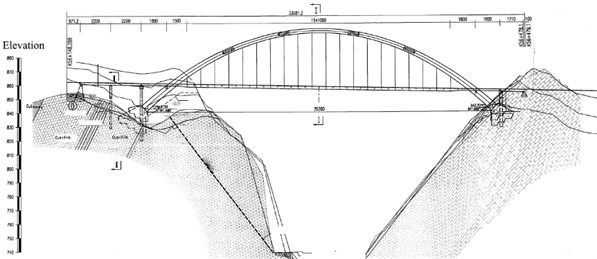
The bridge starts and ends at the mileage of k56+148.288~k56+479.1. The main bridge adopts a calculated span of 252 m medium-bearing steel box arch bridge with a sagittal-to-span ratio of 1/4.5 and an arch axis factor of 1.3, as shown in Fig. 1.
Fig. 1General arrangement of the large arch bridge
The main bridge deck system adopts the combined beam lattice system formed by steel longitudinal and crossbeams and concrete deck slabs. In the boom area, the crossbeam is divided into boom crossbeam and sub-crossbeam, the boom crossbeam corresponds to the boom position, the crossbeam is 30.4 m long transversely and 10 m apart longitudinally, the sub-crossbeam is set in the middle of every two adjacent boom crossbeams. The longitudinal beams are divided into 2 major categories: side longitudinal beams are set in 2 rows longitudinally on both sides of the bridge with a spacing of 24.75 m, and 5 rows of middle longitudinal beams are set in between with a transverse spacing of 4.1m, and both longitudinal and transverse beams are I-beam sections. The steel structure is made of Q345qD steel, and the steel beam parameters are shown in Table 1. The steel girders and reinforced concrete deck slabs are formed by ML15 welded shear keys arranged at the wet joints.
Table 1Geometric parameters of the combined lattice bridge deck system (mm)
Components | Cross-sectional forms | Top plate width×thickness | Base plate width×thickness | Web thickness |
Side longitudinal beam | I-beam | 750×24 | 750×28 | 20 |
Center longitudinal beam | I-beam | 600×16 | 600×20 | 16 |
Boom crossbeam | I-beam | 700×28 | 1000×32 | 24 |
Sub-crossbeam | I-beam | 600×16 | 600×20 | 16 |
3. Computational analysis
3.1. Computational models
According to the St. Venant principle, the bridge deck structure with 3 standard segmental lengths in 3 boom areas was selected and the Midas FEA NX software was used to establish a refined finite element calculation model of the 1/2 structure by using symmetry at the same time. In order to further simulate the fatigue characteristics of the steel-composite girder lattice deck structure accurately, the concrete deck slab and the steel girder lattice structure are simulated by using 3D solid units and plate units respectively, without considering the slip effect between the steel girder and the concrete slab, and the two interfaces are handled by nodal coupling, and the model units and parameters are shown in Table 2.
The model has a total of 150464 nodes and 272221 units, with vertical restraint applied to the lifting point of the boom crossbeam to simulate the boom, symmetric restraint applied at 1/2 structural position, solidification at one end of the longitudinal main beam, and vertical restraint added at another point, the calculation model is shown in Fig. 2.
Table 2Table of cell and material parameters used in the model
Structural parts | Cell type | Elastic modulus (MPa) | Poisson’s ratio |
Concrete bridge deck slabs | Entity cell | 3.252e4 | 0.2 |
Steel beam lattice structure | Board cell | 2.1e5 | 0.3 |
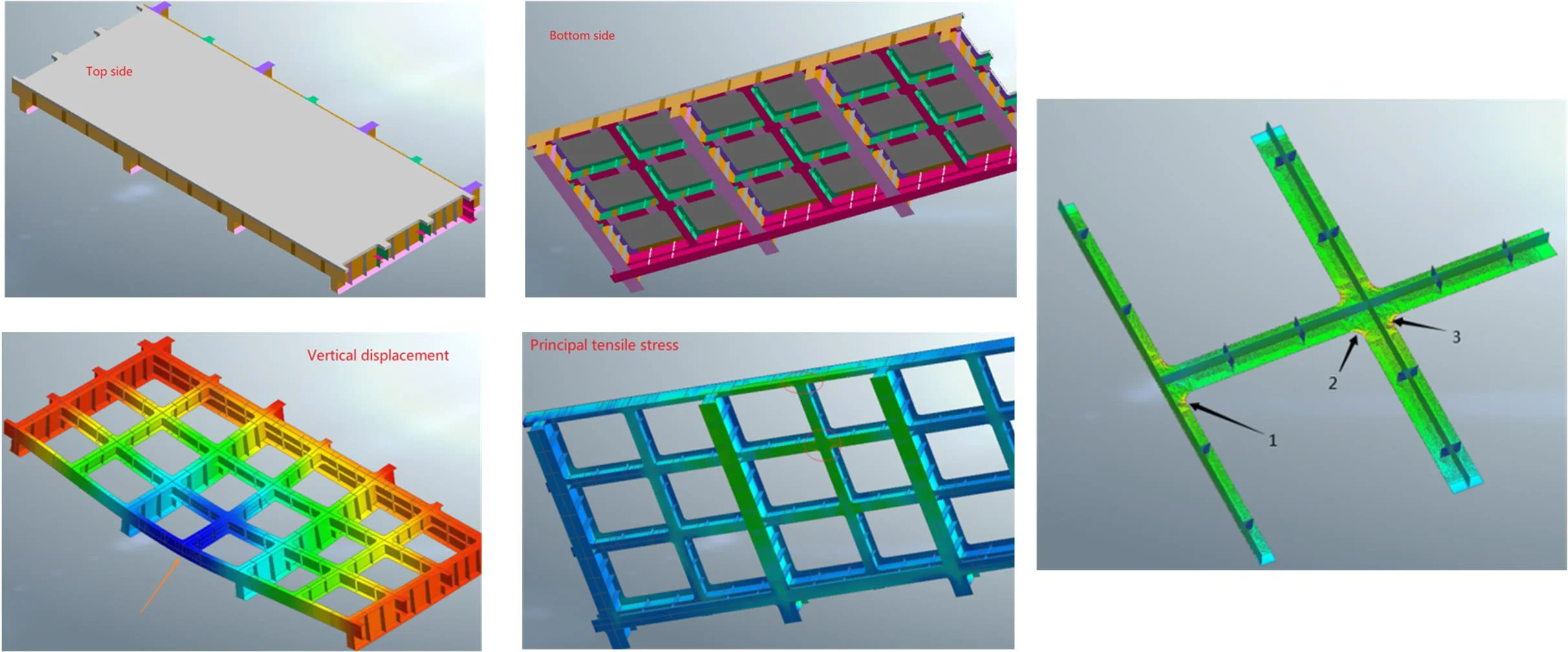
Fig. 2Calculation model
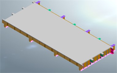
a) Top side
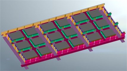
b) Bottom side
3.2. Fatigue loading
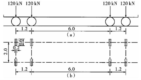
At present, three main styles are generally used for fatigue design load verification of highway bridges, such as standard fatigue vehicle, measured traffic vehicle load spectrum and a heavy vehicle, i.e., a single heavy vehicle in standard live load. Among them, the vehicle load spectrum and the standard fatigue vehicle model are widely used by domestic and foreign scholars and codes because they can equivalently replace the vehicle load on the bridge in the fatigue analysis. In the General Specification for Highway Bridge Design (JTG D60-2015) and the Specification for Design of Highway Steel Bridges (JTG D64-2015) in China, the provisions for fatigue loads are roughly the same, and there are three calculation models I~III for fatigue loads. among them, the calculation model III is a single-vehicle model, as shown in Fig. 3. The calculation model III is a four-axle vehicle with a total vehicle weight of 480 kN, which is mainly used for the verification of the bridge deck system components. Considering the diffusion effect of 0.1 m thick asphalt concrete paving layer, the landing area of the wheels on the concrete deck plate is calculated as 0.4 m×0.8 m, and the vehicle wheel load is applied to the top surface of the concrete deck plate according to the pressure load, i.e. 0.125 MPa.
Fig. 3Schematic diagram of the loaded vehicle for fatigue calculation model III (m)
3.3. Fatigue critical points
Usually, fatigue of steel-composite deck systems is divided into fatigue of shear connectors, fatigue of steel members and fatigue of concrete deck slabs [7]. According to the previous engineering experience and the specification on fatigue details [8], [9], the fatigue-prone points on the steel girder lattice structure are selected as the object of study in this paper. The fatigue-prone critical points on the steel beam lattice structure, i.e., fatigue construction details also called fatigue details, are critical in determining the fatigue load carrying capacity of the structure.
In order to perform fatigue analysis on the steel beam lattice structure, it is necessary to determine the fatigue-prone critical points on the steel beam lattice structure, i.e., the most unfavorable force areas of the structure under the action of vehicle load. In this paper, the loaded vehicles specified in China’s specification fatigue calculation model III are selected, and 2 vehicles are arranged on the centerline of 2 lanes in the 1/2 model span at the same time, and the calculation results of vertical displacement and main tensile stress cloud are obtained, as shown in Fig. 4. From Fig. 4(a), the maximum value of vertical displacement is 6.6 mm, which is located in the middle of the span and the direction is vertical downward; from Fig. 4(b), the maximum principal tensile stress is 44.5 MPa, which appears at the intersection of the middle longitudinal beam and the secondary crossbeam (bottom plate).
Fig. 4Cloud plot of model calculation results
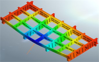
a) Vertical displacement
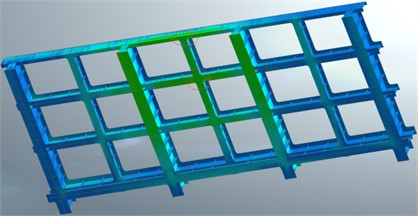
b) Principal tensile stress
Fatigue damage often appears first at the most unfavorable location of the force. In this paper, based on structural symmetry and combined with previous engineering experience, three fatigue critical points are identified at the intersection of the last longitudinal beam and the middle longitudinal beam of the combined lattice beam: (1) the bottom plate of the intersection of the middle longitudinal beam and the second longitudinal beam (outside), (2) the bottom plate of the intersection of the second longitudinal beam and the second longitudinal beam (inside), (3) the bottom plate of the intersection of the second longitudinal beam and the second longitudinal beam ( outside). In order to study the fatigue performance of the above key fatigue-prone parts, the local grid is encrypted at the key details with a minimum cell size of 5 mm, and the details of the specific parts are shown in Fig. 5.
4. Fatigue performance evaluation
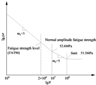
The S-N curve of DNV code C (FAT90) level can be used as the stress-fatigue strength level of this bridge [10][11]. The curve is divided into three sections, the first and second sections are sloping straight lines with slopes of 1/3 and 2/3, respectively. The fatigue strength stress amplitude corresponding to this curve at 2 million cyclic loads is 90 MPa, the constant amplitude fatigue strength limit is 52.6 MPa, and the variable amplitude fatigue cutoff limit is 32.2 MPa. The double logarithmic coordinate system is shown in Fig. 6.
Based on the determined fatigue critical point stress spectrum, a Palmgren-Miner linear cumulative damage was used for fatigue life assessment:
where: is the equivalent stress amplitude; is the key point stress spectrum value of the ith cause fatigue damage stress amplitude; is each stress amplitude corresponding to the number of cycles; is the slope of the curve S-N, here taken 3.
From Eq. (1), the equivalent force amplitudes corresponding to the three fatigue critical points are calculated, giving 28.65 MPa, 22.76 MPa, 23.97 MPa. It can be seen that the maximum critical point stress amplitude in the longitudinal bridge stress history under the action of the standard fatigue vehicle model is less than the constant amplitude fatigue strength limit, indicating that the structure has infinite life and can meet the design requirements.
Fig. 5Location of fatigue critical points of the combined lattice beam
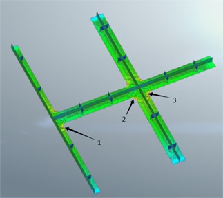
Fig. 6C(FAT90) S-N curve
5. Conclusions
In this paper, a finite element model was established for a steel-composite grillage deck, and the fatigue performance of the structure was studied. The main conclusions are as follows:
1) The steel-composite grillage deck consists of steel plate girders and concrete top plate. The fatigue critical point of the lattice structure is located at the midline of the bridge, and the fatigue stress gradually decreases from the middle to both sides.
2) The fatigue critical point of the lattice structure appears at the intersection of the longitudinal and transverse steel girders bottom plate at the corner coupling, increasing the radius of this place or increasing the thickness of the bottom plate can reduce the fatigue stress amplitude at this place, so that the steel-hybrid lattice structure can obtain better fatigue resistance and longer fatigue life.
References
-
J. G. Nie, Steel – Concrete Composite Bridges. Beijing: China Communications Press, 2011.
-
X. Liu and J. Zhang, “Study on fatigue resistance of composite lattice girder deck slabs for large-span arch bridges,” Western Traffic Technology, pp. 137–140, 2021.
-
“Review of Academic Research on Bridge Engineering in China,” China Journal of Highway and Transport, Vol. 27, No. 5, pp. 1–96, 2014.
-
J. Zhao, W. Li, and T. Feng, “The advance and retreat of highway steel bridges in China,” China Highway, Vol. 11, pp. 25–27, 2016.
-
X. Y. Luo, Y. J. Ni, and G. Ma, “Calculation of deformation of steel-concrete composite beams under fatigue loading,” Road Traffic Science and Technology, Vol. 39, No. 5, 2022.
-
H. Yu, “Study on fatigue performance of steel-hybrid composite girder bridges,” Highway, Vol. 62, No. 8, 2017.
-
Y. Liu, X. L. Li, and D. Wang, “Fatigue damage of steel-composite deck systems under vehicular loading,” Transportation Science and Engineering, Vol. 31, No. 2, 2015.
-
BS5400 Steel, Concrete and Composite Bridges. London, 1979.
-
“GB 50017-2003, Steel Structure Design Specification,” China Standard Publishing House, Beijing, 2003.
-
Q. Zhang et al., “Study on fatigue characteristics of new large longitudinal rib orthotropic steel-concrete composite bridge deck slabs,” Highway, Vol. 60, No. 12, 2015.
-
Q. Zhang et al., “Mechanical properties of new orthotropic composite bridge deck with large longitudinal ribs,” Bridge Construction, Vol. 47, No. 3, 2017.
About this article

The authors have not disclosed any funding.
The datasets generated during and/or analyzed during the current study are available from the corresponding author on reasonable request.
The authors declare that they have no conflict of interest.
