Abstract
The task of measuring of rotating shafts angular deformation by means of ultrasonic vibration meter is considered in the article. Measurement of vibration parameters of rotating objects is an urgent task in the technical diagnostics of electromechanical units, turbines, drilling rigs and metal-cutting machines subject to vibration disturbances. The measured vibration parameters of rotating shafts include their angular deformation and torques arising from torsional vibrations of shafting of machines in the stationary and mobile objects. Timely monitoring of the torsional vibrations of the shafting and other factors of vibration disturbances by the frequency of shaft beats makes it possible to identify defects at an early stage and eliminate breakdowns that threaten the life and safety of personnel. It was found out that the reflected acoustic signal phase measurement relative to the reference one incident onto the investigated shaft surface can be carried out with error at 0.6 % at velocities not more than 0.5 m/s. This article is intended for mechanical engineers involved in the development and operation of rotating machines of stationary and mobile objects.
Highlights
- Proposed a new method of ultrasonic acoustic measurement of angular deformations of rotating shafts.
- The measurements are based on the Doppler effect and frequency deviation estimation.
- The proposed high-precision non-contact measurement method is limited by the spectral composition and vibration velocity of the investigated object.
- Measurement of reflected acoustic signal phase relative to the reference one incident onto the investigated shaft surface can be carried out with 0.6% error only at shaft speed not above 0.5 m/s.
1. Introduction
Usually mechanical oscillations (vibrations) that occur in technological units and in electromechanical complexes (EMCs) are undesirable phenomena. Therefore, there is a need for continuous monitoring of motion and vibration parameters, as well as a comprehensive assessment of the state of machines with rotating shafts [1-5].
Experience in the construction and operation of technological units, energy-intensive machines, metal cutting machines, instruments and electromechanical complexes indicates the need to obtain information about the motion and vibration parameters of dynamic objects. Nowadays, an urgent task is to obtain information about the radial deformation of rotating shafts in the electromechanical complexes under operation [1-7]. In machines with rotating shafts elastic couplings are used, which absorb axial, radial and angular displacements due to their elastic, damping and dissipative properties [8]. The development of elastic coupling for rotating parts of shafting is a rather complicated technical task. The solution of this problem is related to the torsional vibrations diagnosing of non-uniformly rotating shafts, for example, EMC, in particular for the diesel generator set of an autonomous power system in stationary modes and assessing the elastic and damping properties of the connecting coupling of the units [8].
Existing methods for vibration parameters diagnosing and measuring and technical means for their implementation are based on various physical principles and have certain fields of application.
According to the principle of interaction with the object, all existing methods for measuring the parameters of dynamic objects can be divided into two groups: contact, which implies a mechanical connection of the primary sensor with the object, and non-contact, i.e. not associated with the object by a mechanical connection.
Nowadays the main contact methods for controlling torsional vibrations are strain gauge and torsiography. These methods and also the optical methods are based on the discrete principle of torsional vibrations measuring. Using of these methods of torsional vibrations measuring in case of evaluation the damping properties of elastic couplings during the machine operation lead to significant problems [8, 9]. Contact measuring sensors and communication lines are exposed to mechanical and thermal influences that are harmful from the point of view of reliability, which lead to often and costly failures in monitoring systems [7, 9, 10].
Therefore, when studying the angular deformation of the rotating shafts of the EMC, non-contact ultrasonic phase vibration displacement meters are indispensable as primary sensors. Among all of non-contact methods, acoustic methods are the most suitable for these aims, since they have the same physical nature as the investigated processes. Other non-contact methods impose additional conditions on the measured object, for example, optical methods require surface preparation, etc. [8, 9, 11].
Currently, the studies of scientists are aimed at creating systems for active and semi-active vibration damping, as evidenced by the increasing number of publications in foreign countries. The topic of this article is relevant and timely for Russian Science and is based on the works of well-known authors in the field of mechanical engineering: B. A. Gordeev, V. I. Erofeev, A. V. Sinev, D. V. Balandin, M. M. Kogan, K. V. Frolov and others, as well as the works of V. V. Kazakov on metrological assurance of acoustic measurements [11-14].
Measurement of the vibration parameters of rotating objects is an urgent task in the technical diagnostics of EMC [15, 16]. The measured vibration parameters of rotating shafts include their angular deformation and torques arising from torsional vibrations of shafting of EMC [17]. Timely monitoring of shafting torsional vibration makes it possible to detect defects at an early stage and eliminate breakdowns that threaten the life and safety of personnel [18].
The importance of this study is due to the problems of mechanical engineering, and the scientific validity is expressed in the use of non-contact ultrasonic phase methods for measuring the angular deformation of rotating shafts for solve this problem. The use of ultrasonic non-contact methods and means of vibration measuring to solve this problem allows us to solve this problem, but only in terms of measuring vibration overloads of smooth rotating shafts or waves directed along the normal to the probing beam. Acoustic methods for vibration parameters measuring have long been used in mechanical engineering and have been well studied [15, 16].
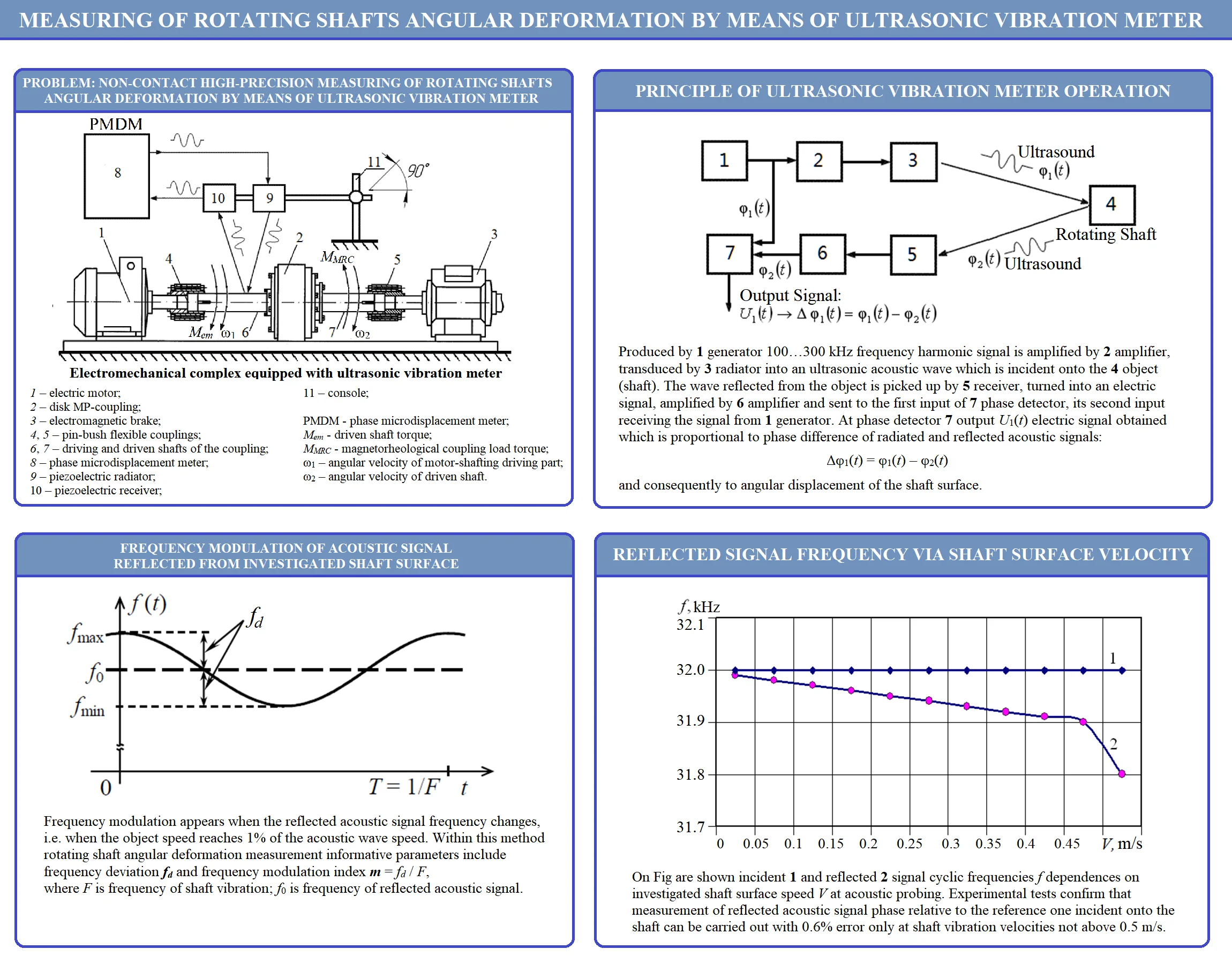
In order to study the angular deformation of rotating shafts, an electromechanical drive-coupling-brake system was chosen (Fig. 1) [14, 19]. This electromechanical system will be investigated by means of experimental measurements of the angular deformation of the rotating shafts of the magnetorheological coupling (MR-coupling) and electromagnetic brake using a non-contact ultrasonic phase vibration meter. MR-couplings have the properties of electromagnetic, friction, powder and hydraulic couplings. A magnetorheological fluid is used as an adhesive layer in an MR-coupling [19].
To study the angular deformation of the rotating shafts of the MR-coupling, an experimental stand was designed and assembled (Fig. 1).
The stand consists of an electric motor 1 with a power of 2.5 kW and a rotor speed of 2770 rpm, a disk MR-coupling 2 and an electromagnetic brake 3 of the PT 2.5-M1 brand. The brake generates a torque in the range of 0...25 N·m in the speed range of 0...4000 rpm. The driving and driven shafts 6 and 7 of the coupling 2 are connected by pin-bush couplings 4 and 5. The electric drive is connected to a 380 V network through a E2-8300 frequency converter allowing to change the motor speed in the range from 50 to 4000 rpm.
Measurement of the angular deformation of the rotating shafts of the MR-coupling is used to evaluate its damping properties. The basis for evaluating the damping properties of an MR-coupling is to determine the ratio of torque pulsations caused by torsional vibrations on its rotating driving and driven shafts. In addition, by comparing the current values of the ratio of torque imbalances on the MR-coupling rotating shafts with their reference values, the protection of EMCs can be provided through the monitoring of the shafting torque signals. This eliminates the emergency operation of generating and industrial units.
Fig. 1Electromechanical subsystem of the experimental stand: 1 – electric motor, 2 – disk MR-coupling, 3 – electromagnetic brake, 4, 5 – pin-bush flexible couplings, 6, 7 – drive and driven shafts of the coupling
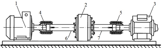
To measure the angular deformation of the rotating shafts of the MR coupling, a non-contact ultrasonic phase microdisplacement meter (PMDM) developed by the authors is used. The operation of ultrasonic PMDM is described in [12, 14]. To study the angular deformation of the rotating shafts of the MR-coupling, Fig. 2 shows an electromechanical drive-coupling-brake system with non-contact ultrasonic PMDM [12, 14].
Fig. 2Experimental stand equipped with non-contact ultrasonic PMDM: 1 – electric motor, 2 – disk MP-coupling, 3 – electromagnetic brake, 4, 5 – pin-bush flexible couplings, 6, 7 – driving and driven shafts of the coupling, 8 – phase microdisplacement meter, 9 and 10 – piezoelectric incident and receiving elements, 11 – console
The equation for the driving shaft of the MR-coupling can be written as follows:
where is driving shaft torque, – electromagnetic torque of motor, – load torque caused by bearing and sealing friction, – load torque of MR-coupling, – moment of inertia of motor-shafting driving part, – angular velocity of motor-shafting driving part, – angular acceleration of motor-shafting driving part, – angular velocity of driven shaft.
2. Ultrasonic vibration meter based on Doppler effect
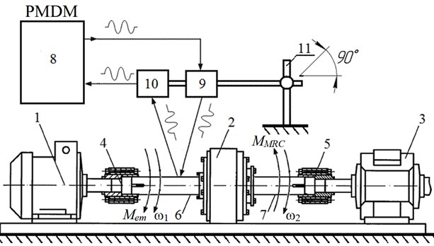
Determining shafts deformation by ultrasonic phase vibration displacements meter is based on comparing phases of direct (incident) and returned (reflected) at the shaft ultrasonic signals [14]. The diagram of ultrasonic vibration meter reading off the shaft surface angular displacement through phase mismatch of ultrasonic signals is shown on Fig. 3.
Produced by 1 generator 100…300 kHz frequency harmonic signal (Fig. 3) is amplified by 2 amplifier, transduced by 3 radiator into an ultrasonic acoustic wave which is incident onto the 4 object (shaft) [14]. The wave reflected from the object is picked up by 5 receivers, turned into an electric signal, amplified by 6 amplifier and sent to the first input of 7 phase detector, its second input receiving the signal from 1 generator. At phase detector 7 output electric signal obtained which is proportional to phase difference of radiated and reflected acoustic signals and, consequently, to angular displacement of the shaft surface [14].
Fig. 3Flowchart of ultrasonic vibrometer: 1 – harmonic signal generator, 2 – amplifier, 3 – acoustic radiator, 4 – investigated shaft, 5 – acoustic receiver, 6 – amplifier, 7 – phase detector
Probing ultrasonic signal frequency is selected basing on evaluative parameters of rotating shaft measured angular velocity. Thus, at angular displacement values in range of 1-10” (angular seconds) ultrasonic signals of 1.0…3.0 mm wavelength is preferable which corresponds to 100…300 kHz frequency for the air. Measuring angular delay consists of measuring phase difference of radiated and reflected harmonic signals [14]:
where is reflected signal delay relative to the radiated one; and are ultrasonic signal period and frequency respectively.
Measuring angular deformations by wave methods is the following [14]. Acoustic field at any given time and at any spatial point is completely determined by dependence of one out of the three interrelated variables: is displacement vector of medium particle out of idle position; is oscillating speed vector; is acoustic pressure in the medium.
Each of these values at any given time and at any spatial point satisfies wave equation [20]:
where ∇ is Laplace operator; is sound speed in the air.
By means of wave equation Eq. (2) it is possible to obtain spatial and time distribution of any values characterizing the acoustic field. Eq. (2) describes medium displacements caused by probing signal source, which can be presented disregarding boundary conditions as follows [14, 20]:
where: and are laws of wave propagation in space and time respectively, is sound speed in the medium, is the medium elasticity modulus, ρ is the medium density [13].
Ultrasonic wave radiated by the source is used as a probing signal and determined by Eq. (3). Assume that on the boundary ( 0) a probing signal source and a compatible receiver are located. Then the continuity condition on this boundary can be presented as follows:
where is the medium wave resistance, is function determining boundary displacement law [14, 20].
Since the rotating shaft surface impenetrable for the probing signal, the second boundary condition at takes the following form:
where is distance from the source to media fixed boundary, is media boundary displacement law.
Experimental studies have shown that in the case of media boundary displacement going on at constant velocity, boundary displacement law takes the form , where is initial distance from radiating source to the media boundary.
In this case boundary displacement law takes the following form [14, 20]:
Under this boundary displacement law radiated and returned acoustic signals can be expressed as follows:
where and are amplitudes of radiated and returned signals, , , and are radiated and returned acoustic signals cyclic frequencies respectively, is phase shift.
Radiated and returned acoustic signal frequency dependence is determined by Doppler effect:
where is the object’s surface speed.
Fig. 4 shows the returned signal cyclic frequency dependence on shaft surface speed change at acoustic probing.
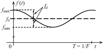
At media boundary displacement according to harmonic law with the speed of reflective shaft surface displacement is a modulating harmonic vibration signal [14, 20]:
where – modulating vibration signal amplitude, – cyclic vibration frequency of the investigated shaft.
Frequency modulation appears when the reflected acoustic signal frequency changes, i.e. when the object speed reaches 1 % of the acoustic wave speed (Fig. 5). The reflected signal frequency change can be represented by the following expression:
where – coefficient of proportionality, is frequency deviation.
Fig. 4Incident 1 and returned 2 signal cyclic frequency dependence on shaft surface speed at acoustic probing
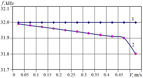
Fig. 5Frequency change range of the acoustic FM-signal reflected from vibrating surface
Within this method rotating shaft angular deformation measurement informative parameters include frequency deviation and frequency modulation index of the reflected acoustic signal caused by Doppler effect and phase modulation [14]:
where and are the reflected acoustic signal circular frequency deviation and the vibrating surface frequency modulation.
Coefficient “” is the index of frequency modulation of the reflected signal depends on the oscillation frequency of the investigated object. Usually, this index can vary from 0 to 1, and depends on the velocity of the object. With an increase in the velocity of the object, the index increases, and becomes equal to 1 when the velocities of the incident signal and the object become equal.
Assuming that media boundary displacement velocity is far less than the speed of acoustic wave propagation . Thus, Eq. (7) can be represented in Fourier series [14]:
where is the distance between the acoustic radiator and investigated object, is the linear velocity of the investigated object (derivative of the distance ), is the phase velocity of the incident ultrasonic wave.
Integrating Eq. (8), the reflected signal phase is found: . If the boundary being displaced according to law , then the reflected wave can be expressed as follows [21]:
where is Bessel function of the first kind of -th order from argument, is frequency modulation index, is the reflected acoustic signal frequency deviation [21].
3. Spectral analysis of the reflected acoustic signal
In the reflected signal spectrum the share of various harmonics is determined by value frequency modulation index . At frequency and phase modulation both instantaneous frequency and phase of the reflected acoustic signal change. The parameters characterizing these kinds of modulation – frequency deviation and phase deviation – show different dependences on modulating vibration signal frequency [21].
The frequency-modulated ultrasonic signal (hereinafter reflected FM-signal) reflected from shaft vibrating surface Eq. (4) can be represented by series [14, 20, 21]:
where is Bessel function of the first kind of -th order.
Reflected from rotating shaft surface FM-signal spectrum is determined by expression:
where is Fourier series amplitude ratios at 0.
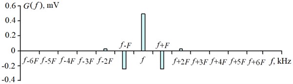
At 2.5 fundamental harmonic with frequency is equal to zero. In this case, fundamental spectral component in the signal reflected from the shaft can be appear. An example of such reflected FM-signal experimental spectrum at 2.5 for vibration displacements 2 mm is shown in Fig. 6.
In the Fig. 6-8 the frequency 32 kHz is the frequency of the incident ultrasonic signal, the frequency 10 Hz is the vibration frequency of the surface of investigated object.
From Fig. 6 it follows that the power level of fundamental harmonic with frequency in the reflected acoustic wave is close to zero.
From Eq. (9) and Eq. (11) it follows that lower odd components are different from corresponding upper ones by a phase angle equal to , which provides amplitude constancy of the reflected FM-signal having angular modulation, for example at 1. At frequency modulation the returned acoustic signal spectrum reflected from the rotating shaft surface has an infinite number of spectral components. These components are located symmetrically relative to the probing acoustic signal frequency at intervals multiple of vibration frequency . Spectral components frequencies are equal to , and the amplitudes are equal to . An analogous result is obtained at phase modulation of acoustic signal reflected from the shaft surface by substituting parameter for [14, 21].
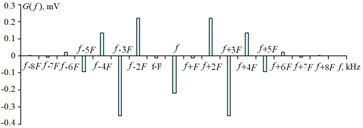
Through the Eq. (11) spectra of FM-signals reflected from the rotating shaft surface are calculated with their frequency and phase modulation at the given values . Spectrum of the reflected FM-signal with 0.6 at vibration displacement 0.5 mm is shown in Fig. 7.
Fig. 6Reflected acoustic signal spectrum with frequency modulation at given parameters: f= 32 kHz; F= 10 Hz; s= 2.0 mm; m= 2.5
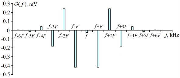
Fig. 7Reflected acoustic signal spectrum with frequency modulation at given parameters: f= 32 kHz; F= 10 Hz; s= 0.5 mm; m= 0.6
Theoretically, spectrum of FM-signal reflected from rotating shaft vibrating surface (especially at 1) is infinite [14, 21]. The higher the modulation index value, the broader is the frequency band held by the reflected FM-signal. However, according to the analysis, the greater part of FM-signal energy is concentrated within the band:
where – cyclic vibration frequency in the reflected FM-signal spectrum.
Bandwidth path of ultrasonic phase vibration converter should be calculated basing on this very value. At 1 acoustic FM-signal spectrum width: .
At 1, value is more or less uniform at all integer values , smaller than argument . At , close to , produces a wavelet, whereas at further increase function quickly decreases to zero. General outline of this experimental spectrum for 3.8 is shown in Fig. 8.
Setting maximum value equal to , allows one to make a conclusion that the overall bandwidth of the reflected FM-signal will be equal to . Consequently, at greater modulation indices the bandwidth of reflected FM vibration is close to double frequency deviation. Thus, for modulation index 3.8 the bandwidth of reflected acoustic vibration is limited by frequency band (Fig. 8). It is possible to state the following: at quick angular modulation (when ) the bandwidth of the reflected acoustic vibration is close to 2 value; at slow angular modulation (when ) the bandwidth is close to 2value.
Fig. 8Reflected acoustic signal spectrum with frequency modulation at given parameters: f= 32 kHz; F= 10 Hz; s= 3.0 mm; m= 3.8
4. Conclusions
Experimental tests confirm that measurement of reflected acoustic signal phase relative to the reference one incident onto the investigated shaft surface can be carried out with 0.6 % error only at shaft speed not above 0.5 m/s. If rotating shaft speed exceeds the beat speed, then the frequency deviation of the reflected signal emerges, extra harmonics appearing in its spectrum. The error of the reflected signal was estimated using a special calibration stand, the reflecting surface of which was moved with a micrometer screw at a speed of 10-3 m/s. Therewith, fundamental harmonic amplitude decreases and if phase changes continue, then they can be conducted not along the fundamental harmonic but along the adjacent harmonic with a greater amplitude. If that harmonic is opposite in phase to the fundamental harmonic, measurement error may exceed 3 %, which is inadmissible.
The results of performed studies have shown that the use of non-contact ultrasonic phase methods can improve the metrological accuracy of shaft beats measuring and estimating the angular deformation of rotating shafts.
References
-
M. Luintel, “Dynamic modelling and response of a pelton turbine unit,” Ph.D. Thesis, Lalitpur, Nepal, 2019.
-
M. Eftekhari, A. D. Rahmatabadi, and A. Mazidi, “Magnetic field effects on the nonlinear vibration of a rotor,” Applied Mathematics and Mechanics, Vol. 41, No. 2, pp. 289–312, Feb. 2020, https://doi.org/10.1007/s10483-020-2567-6
-
M. Friswell, J. Penny, S. Garvey, and A. Lees, Dynamics of Rotating Machines. Cambridge: Cambridge University Press, 2010.
-
B. Bozorgmehri, V.-V. Hurskainen, M. K. Matikainen, and A. Mikkola, “Dynamic analysis of rotating shafts using the absolute nodal coordinate formulation,” Journal of Sound and Vibration, Vol. 453, pp. 214–236, Aug. 2019, https://doi.org/10.1016/j.jsv.2019.03.022
-
Sanjiv Kumar, R. Sehgal, and Sanpreet Singh, “Vibrations signature analysis of whirling shaft of varying diameters operated at varying speeds,” Journal of Physics: Conference Series, Vol. 1240, p. 01215, 2019.
-
W. Zhou, X. Wei, L. Zhai, X. Wei, and L. Wang, “Nonlinear characteristics and stability optimization of rotor-seal-bearing system,” Journal of Vibroengineering, Vol. 16, No. 2, pp. 818–831, Mar. 2014.
-
O. Matsushita et al., Vibrations of Rotating Machinery: Volume 1. Basic Rotordynamics: Introduction to Practical Vibration Analysis. Tokyo: Springer Japan, 2017.
-
K. Wu, Z. Liu, and Q. Ding, “Vibration responses of rotating elastic coupling with dynamic spatial misalignment,” Mechanism and Machine Theory, Vol. 151, p. 103916, Sep. 2020, https://doi.org/10.1016/j.mechmachtheory.2020.103916
-
H. Luo, R. Chumai, N. Peton, and A. Menon, “Keyphasor® based torsional vibration detection and field applications,” Proceedings of the 9th IFToMM International Conference on Rotor Dynamics, Vol. 21, pp. 233–253, 2015, https://doi.org/10.1007/978-3-319-06590-8_19
-
A. Goroshko, V. Royzman, and M. Zembytska, Book Series on Vibroengineering. JVE International, 2014, https://doi.org/10.21595/9786099603636
-
V. V. Kazakov, “Measurement of the oscillation field by ultrasonic phase vibrodisplacement meters,” (in Russian), in Proceedings of XV session of the Russian Acoustic Society “Acoustic measurements”, 2004.
-
V. I. Erofeev, A. V. Vanyagin, S. N. Okhulkov, and Et. Al., “Applicability conditions for linear models describing the propagation of acoustic waves,” (in Russian), Russian Engineering Research, Vol. 6, pp. 18–20, 2021.
-
V. L. Gaponov, A. S. Gurinov, and V. V. Dudnik, “Measurement of torque on rotating shafts,” (in Russian), Vestnik DGTU, Vol. 1, No. 162, pp. 25–32, 2012.
-
B. A. Gordeev, S. N. Okhulkov, A. N. Osmekhin, and A. S. Plekhov, “The influence of the Doppler effect on the error of vibration measurement of electromechanical complexes by wave methods,” (in Russian), NNSTU n.a. R.E. Alekseev Proceedings, Vol. 2, pp. 56–61, 2017.
-
M. D. Genkin and A. G. Sokolova, “Vibroacoustic diagnostics of machines and mechanisms,” (in Russian), Moscow, 1987.
-
V. N. Kostukov and A. P. Naumenko, Fundamentals of Vibroacoustic Diagnostics and Monitoring of Machines: Textbook. (in Russian), Omsk: OmGTU Publishing, 2011.
-
L. V. Efremov, Theory and Practice of Research of Torsional Vibrations of Power Plants Using Computer Technologies. (in Russian), Saint-Petersburg: Nauka, 2007.
-
A. L. Nazolin, Prevention of Accidents and Catastrophes of Rotating Equipment of Critically and Strategically Important Objects of the Technosphere: (On the Example of Powerful Turbine Units of Nuclear and Thermal Power Plants): Scientific Report. (in Russian), Moscow: Russian Academy of the Sciences Publishing, 2017.
-
A. N. Gurskii, “Analysis of the dynamics of magnetorheological clutches and brakes,” (in Russian), Problems of Tribology, Vol. 1, pp. 71–80, 2010.
-
A. Ango, Mathematics for Electrical and Radio Engineers. (in Russian), Moscow: Nauka, 1967.
-
I. S. Gonorovskiy, Radio Engineering Circuits and Signals. (in Russian), Moscow: Sovetskoe Radio, 1979.
About this article

The research was funded by Russian Science Foundation (Project No. 20-19-00372).
The datasets generated during and/or analyzed during the current study are available from the corresponding author on reasonable request.
Artem Ermolaev – software, visualization, writing – review and editing; Boris Gordeev – conceptualization, formal analysis; Sergei Okhulkov – investigation, writing – original draft preparation; Grigory Panovko – methodology, validation, writing – review and editing; Alexander Plekhov – investigation, project administration, supervision.
The authors declare that they have no conflict of interest.
