Abstract
The methods of arranging frame spacing are explored for reducing the vibration of a cylindrical shell. According to the principle that an aperiodic structures will produce irregular reflections on structural waves, resulting in structural vibration attenuation, two methods of arranging frame spacing are adopted: periodic frame spacing and random frame spacing. Using the two methods, the frames of cylindrical shell models are arranged, and then, using the finite element method (FEM), the vibration response of the cylindrical shells is calculated and compared. It can be found that, for the finite-length cylindrical shells, the aperiodic arrangement of the frame spacing can decrease the vibration level of the cylindrical shells in some specific high-frequency band. For example, for the cylindrical shells with a diameter of 7.6 m and a length of 8.4 m, the frame-spacing arrangement is random, and the vibration level is reduced in about 350-600 Hz, with a maximum reduction of up to 9 dB.
Highlights
- A new train of thought of aperiodic frames is developed for decreasing vibration of the cylindrical shell.
- A new design method of frame spacing is explored for reducing the vibration of a cylindrical shell.
- The influence of the form of the frame arrangement on the vibration of the cylindrical shell is mainly in the middle and high frequency range, not obvious in the low frequency range.
- In some frequency range, the aperiodic arrangement of the frame spacing can decrease the vibration of the cylindrical shell.
1. Introduction
A submarine is mainly composed of a framed cylindrical shell, so the vibration characteristics of the framed cylindrical shell directly determine the vibration characteristics of the submarine. In addition, with the development of modern sonar systems and numerous advanced underwater detection technologies, the concealment of submarines is extremely important in modern warfare. Therefore, it is very important to study the characteristics of the vibration and radiated noise of a framed cylindrical shell, which has always been the focus of many scholars.
So far, in the study of the vibration characteristics of framed cylindrical shells, the arrangement of the frame spacing has usually been periodic. Wang et al. [1] analyzed the free flexural vibration of a cylindrical shell horizontally immersed in shallow water. In Refs. [2] and [3], the semi-analytical method was developed for vibro-acoustic analysis of submerged ring-stiffened cylindrical shells. Using analytical and experimental methods, Zhao et al. [4] analyzed the vibro-acoustic behavior of a semi-submerged finite cylindrical shell. In Refs. [5] and [6], boundary conditions were considered in the study of the vibro-acoustic behavior of cylindrical shells. For a periodic structure, such as coupled multi-span beams [7], a periodically ribbed plate [8-10], or a periodically framed cylindrical shell [11], the study of the vibration characteristics shows that the passband alternates with the stopband in the frequency domain. In the passband, the vibration of periodic structure can propagate freely, but in the stopband, the vibration of periodic structure exponentially decays away from the source.
At present, the study of aperiodic structures is mostly focused on one-dimensional structures or other simple structures, such as mono-coupled multi-span beams with large deterministic disorders [12], rectangular plates and membranes under fluid loading [13, 14], and disordered multi-span beams with damping [15-18]. Several important conclusions have been drawn, e.g., Anderson localization exists in the vibration characteristics of aperiodic structures [19-21]. Not many studies on the vibration characteristics of a cylindrical shell with frame aperiodicity exist [22-24], and those that do are mainly aimed at infinite-length cylindrical shells [25]. The results in [25] show that, except for the low-order vibration mode in the circumferential direction, the obvious phenomenon of Anderson localization exists and is increasingly obvious with increasing order of the circumferential-direction vibration mode. The main reason is that, with increasing order of the circumferential-direction vibration mode, the effect of the frame impedance increases, and the coupling action between the adjacent sub-structures is weakened by the influence of the frame impedance.
In practical engineering, a framed cylindrical shell is of finite length. In this paper, the control effect of the frame aperiodicity on the vibration of a cylindrical shell is investigated. The analysis method used in this paper is of practical significance for the study of the vibration mechanism of cylindrical shells, and the conclusions drawn herein can be used to guide the design of cylindrical shells.
2. Basic theory
2.1. Vibration localization of aperiodic structures
According to the vibration characteristics of simple structures, such as one-dimensional aperiodic mass-spring chain models, and one-dimensional aperiodic bending beams, the generation of vibration localization mainly meets the following two conditions [25]:
1) The parameter arrangement of the substructure is random.
2) The larger the number of the substructure, the quicker the amplitude of the structural wave decays with increasing propagating distance.
When the sum of frames is enough, and the frame spacing is random, then the vibration localization may be found for finite-length cylindrical shell.
The detailed positions of the frames along the shell are distributed randomly within a small region about the nominal periodic location; i.e., the probability density that the position of a particular frame near has position is:
where is the mean spacing of the frames along the shell, is the number of a particular frame, is the maximum deviation of the position of a frame from its nominal periodic location. reflects the extent to which the detailed positions of the frames along the shell are distributed randomly. For finite-length cylindrical shell, in order to obtain obvious vibration localization effect, the should be increased as much as possible under the condition of guaranteeing the random distribution of frames spacing.
2.2. Calculation method of vibration localization
The mean square normal velocity of the surface is adopted to show the vibration characteristics of the framed cylindrical shell. For the arbitrary surface , the normal velocity distribution of the shell is , and the mean square normal velocity of the shell can be obtained:
where is time, is integration time length, is area of .
At the typical frequency of the excited force, the vibration response of the cylindrical shell was calculated by FEM. Then, the mean square normal velocity was obtained by using the vibration response as the input [26]:
where is the sum of the finite elements of the shell, is the amplitude of the normal velocity at the centroid of the ’th element, the area of the ’th element. By taking the logarithm of , the level is obtained:
where 5.0×10⁻⁵ mm/s is the reference velocity.
By comparing the of the cylindrical shells with frame periodicity and with frame aperiodicity, the reducing vibration effect of a frame-spacing arrangement is explored.
3. Comparison of vibration of framed cylindrical shell
3.1. Structural design of framed cylindrical shell
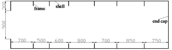
For the studied cylindrical shell with frame periodicity, the frame spacing was 0.6 m, the shell thickness 0.028 m, and the length 8.4 m, and the bulkhead on the two sides was kept invariant; the structural form is shown in Fig. 1.
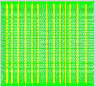
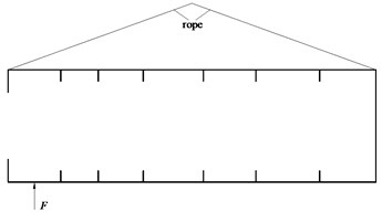
On the base of the above cylindrical shell with frame periodicity, design the random arrangement of frame spacing. The probability density of the position of a particular frame satisfies Eq. (1), in which 0.6 m, equal to 3.5 % of the frame spacing of the cylindrical shell with frame periodicity, 0.035. There were 13 frames for each cylindrical shell; 13, that is to say, 14 frame spacings were generated by the random method, with each measuring 0.4–0.8 m in length. Fifty groups of frame spacings were generated; in other words, 50 framed cylindrical shell models were made, named models 1-50, as shown in Table A1 (in Appendix). Obviously, the arrangement of frame spacing is aperiodic, e.g. the sketches of the frame-spacing arrangement of model 1 is shown in Fig. 2.
Fig. 1Structure design of cylindrical shell with frame periodicity

Fig. 2Frame-spacing arrangement of model 1
3.2. Vibration response of framed cylindrical shell in air
The vibration responses of the cylindrical shell with frame periodicity and frame aperiodicity were separately calculated by FEM in air, and MSC.Patran was used to build the models of the framed cylindrical shell, therefore the accuracy of the calculation was guaranteed.
There are two calculation cases: one is the application of axial exciting force acting on the base of the floating raft, and the other is the application of vertical exciting force acting on the base of the floating raft. The frequency band of the exciting force is 20-1000 Hz, and the calculation result of the mean square normal velocity which was obtained by Eq. (3) is compared and analyzed.
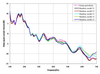
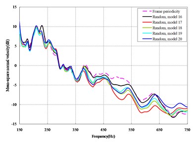
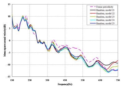
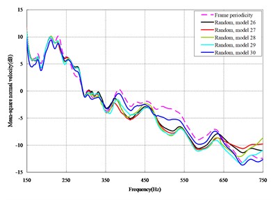
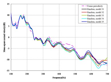
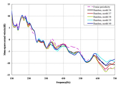
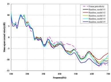
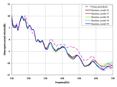
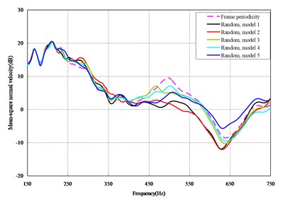
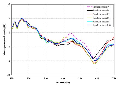
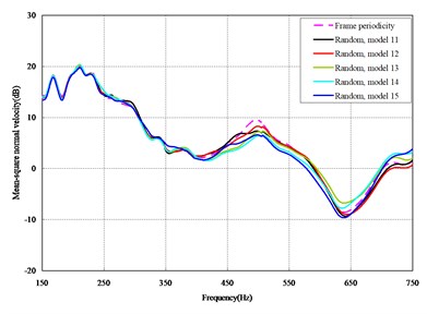
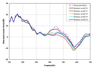
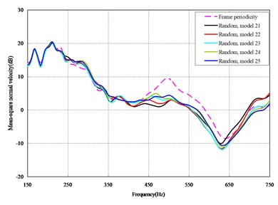
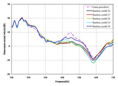
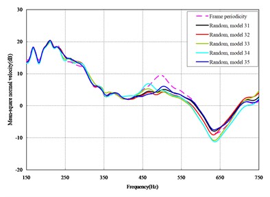
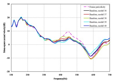
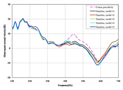
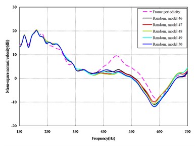
Fig. 3Comparison among 50 models under axial loads
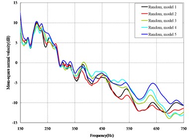
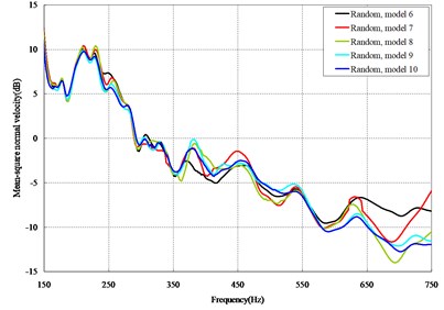
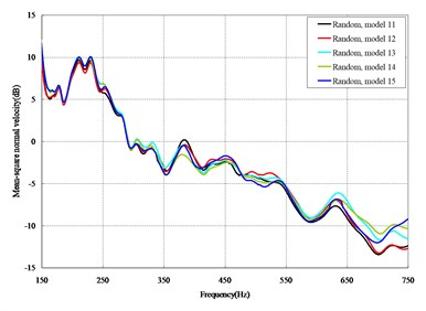
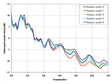
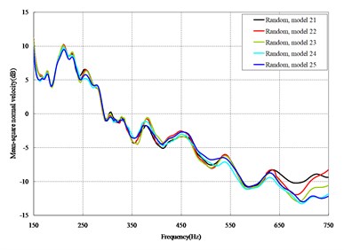
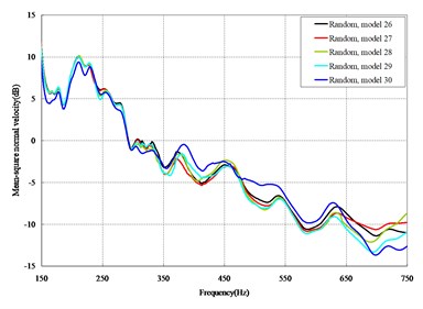
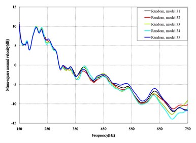
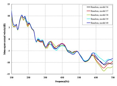
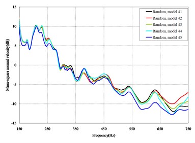
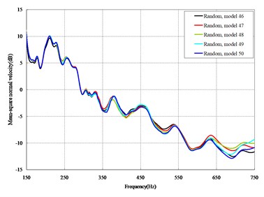
Fig. 4Comparison among 50 models under vertical loads
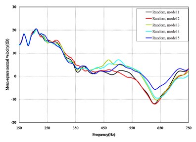
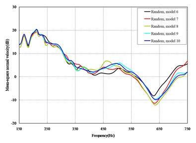
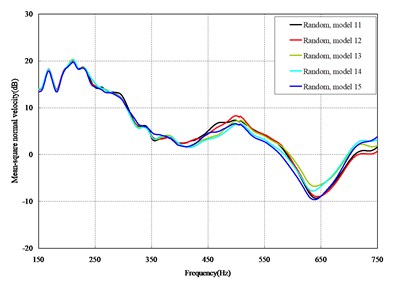
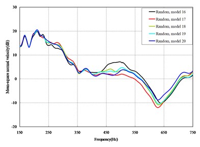
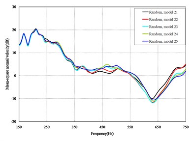
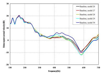
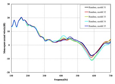
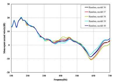
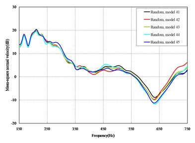
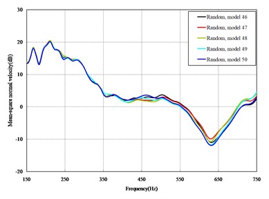
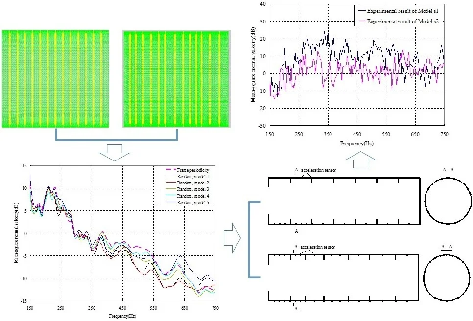
The mean square normal velocity of the 50 cylindrical shells with random frame spacing arrangements introduced in Section 3.1 were compared and analyzed. It can be seen that before 700 Hz, the curves of vibration response cross-connect, and, on the whole, the difference among the results of the 50 cylindrical shells is small, except for some parts, which are shown in Figs. 3 and 4. Fig. 3 plots the vibration response of the case in which axial exciting force acting on the base of the floating raft is applied and Fig. 4 that of the case in which vertical exciting force acting on the base of the floating raft is applied.
The vibrations of the cylindrical shell with frame periodicity and that with a random frame-spacing arrangement were compared, as shown in Figs. 5 and 6. Fig. 5 plots the vibration response of the case in which axial exciting force acting on the base of the floating raft is applied and Fig. 6 that of the case in which vertical exciting force acting on the base of the floating raft is applied.
Fig. 5Comparison between periodic and random arrangements under axial loads
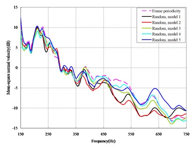
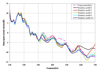
From the results in Figs. 5 and 6, the following conclusions can be drawn:
1) For the finite-length cylindrical shell, when the frequency of the exciting force is less than 350 Hz, the difference in the vibration response between the cylindrical shell with frame periodicity and that with frame aperiodicity is not obvious. The reason is that in the low-frequency band the wavelength of the structural wave is relatively longer, so the method of arranging the frame spacing has little influence on the total vibration of the cylindrical shell. However, with increasing frequency, the wavelength of the structural wave becomes relatively shorter, and thus, the influence of the method of arranging the frame spacing on the total vibration of the cylindrical shell becomes increasingly more obvious. When the frequency of the exciting force is in the range of about 350-600 Hz, compared with the periodic arrangement of the frame spacing, the aperiodic arrangement of the frame spacing can decrease the vibration of the cylindrical shell with a maximum reduction of up to 9 dB.
2) For the finite-length cylindrical shell, the aperiodic arrangement of the frame spacing can decrease the vibration of cylindrical shell, but the effect exists only in some narrow frequency band, generally at medium-high frequency.
Fig. 6Comparison between periodic and random arrangements under vertical loads
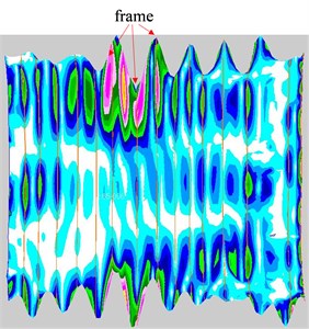
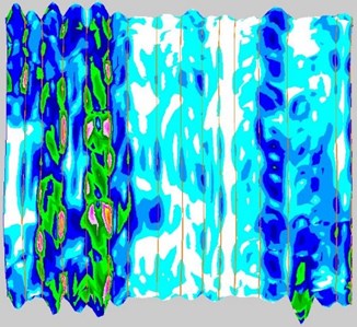
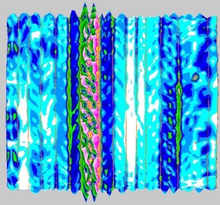
3) Changes in frame spacing mainly affect the propagation of the structural waves between adjacent frames. Taking model 1 as an example, the first 4000-order modes were obtained through numerical simulation, and it can be seen that when the natural frequency is less than 350 Hz, the structural wavelength on the shell plate exceeds the distance between adjacent frames, as shown in Fig. 7(a) and Fig. 7(b), so when the frequency is less than 350 Hz, the change in frame spacing has little effect on vibration. When the natural frequency is greater than 350 Hz, the vibration on the shell plate is dominated by the vibration between adjacent frames, and the structural wavelength is usually less than the distance between adjacent frames, as shown in Fig. 7(c)-7(f), so when the frequency is greater than 350 Hz, the frame-spacing changes affect the vibration, but when the frequency exceeds 600 Hz, the vibration on the shell plate is mainly local vibration, as shown in Fig. 7(g), the effect of frame-spacing changes on vibration is reduced.
Fig. 7Structural wavelength vs. frequency
a) 250.59 Hz
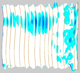
b) 312.95 Hz
c) 350.20 Hz
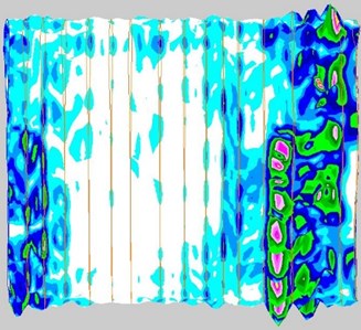
d) 450.15 Hz
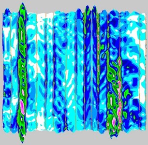
e) 550.33 Hz
f) 590.61 Hz
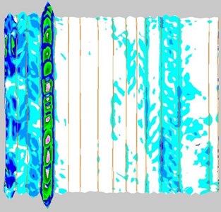
g) 610.69 Hz
4. Experimental verification of the effectiveness of the frame-spacing arrangement method
4.1. Experimental models
There were two experimental models, which were represented by Model s1 and Model s2. The structural scale of both models was the same, only the position of the frames was different. The models are made of steel material, and their main dimensions and material parameters are shown in Table 1.
Both models were arranged along the axial direction of the shell with 6 frames, of which Model s1 was equally spaced, the frame spacing was 700 mm. On the base of Model s1, design the random arrangement of frame spacing. The probability density of the position of a particular frame satisfies Eq. (1), in which 0.7 m, equal to 30 % of the frame spacing of the cylindrical shell with frame periodicity, 0.3. There were 6 frames for each cylindrical shell; 6, that is to say, 7 frame spacings were generated by the random method, with each measuring 0.5-0.9 m in length. Due to the axial length of the experimental models are shorter compared to the models in Section 3.1 of my paper, thirty groups of frame spacings were generated; in other words, 30 framed cylindrical shell models were made, named models 1-30, as shown in Table 2. Obviously, the arrangement of frame spacing is aperiodic. The vibration responses of the cylindrical shells with frame periodicity (Model s1) and frame aperiodicity (models 1-30) were separately calculated by FEM in air, and MSC.Patran was used to build the models of the framed cylindrical shell, therefore the accuracy of the calculation was guaranteed. The frequency band of the exciting force is 1-1000 Hz. On the base of the vibration responses, the mean square normal velocity was obtained by Eq. (3). Calculate the average area enclosed by the “mean square normal velocity” curve and the “frequency” axis for all models according to the following Eq. (5), and the result is expressed in . and in the Eq. (5) represent the upper and lower limits of the integration, respectively, where 1 Hz, 1000 Hz:
Table 1Structure parameters and material
Structure parameters | Material | ||
Cylindrical shell length | 4900 mm | Elastic modulus | 2.05×10⁵ N/mm2 |
Cylindrical shell diameter | 1500 mm | Density | 7.80×10⁻⁶ kg/mm3 |
Shell thickness of cylindrical shell | 6 mm | Poisson ratio | 0.3 |
Plate thickness of end cap | 6 mm | Structural damping coefficient | 0.06 |
Frame height | 150 mm | ||
Frame thickness | 6 mm | ||
Take the logarithm of to get , and represents the total vibration level of the model:
The total vibration level of Model s1 is 10.90 dB, and the total vibration levels of the models in Table 2 are shown in Table 3. It can be seen that the vibration levels of all models in Table 3 are smaller than Model s1. In Table 3, the total vibration level of Model 23 is the smallest, therefore, based on the frame spacing of Model 23, the experimental model with the aperiodic frame-spacing was processed. For the convenience of processing, the frame spacing of Model 23 is fine-tuned, and the experimental model shown in in Fig. 8 is obtained, named Model s2.
Fig. 8Aperiodic frame spacing of Model s2
To facilitate the installation of the exciter, the cylindrical shell was hoisted horizontally (as shown in Fig. 9(a)). The exciter generated a sinusoidal excitation force , which acted on the cylindrical shell through the excitation rod (as shown in Fig. 9(c)). To simulate the free boundary conditions, the cylindrical shell was suspended at both ends, and connected to the hoisting equipment with a soft rope (as shown in Fig. 9(b)).
Table 2Aperiodic frame spacing of all models for experiment
Model name | 1st frame spacing (mm) | 2nd frame spacing (mm) | 3rd frame spacing (mm) | 4th frame spacing (mm) | 5th frame spacing (mm) | 6th frame spacing (mm) | 7th frame spacing (mm) |
Model 1 | 700 | 880 | 580 | 630 | 860 | 540 | 710 |
Model 2 | 530 | 730 | 830 | 710 | 690 | 820 | 590 |
Model 3 | 690 | 710 | 740 | 510 | 680 | 790 | 780 |
Model 4 | 590 | 830 | 650 | 860 | 700 | 670 | 600 |
Model 5 | 630 | 800 | 640 | 570 | 750 | 660 | 850 |
Model 6 | 700 | 650 | 900 | 660 | 770 | 620 | 600 |
Model 7 | 620 | 850 | 820 | 510 | 540 | 720 | 840 |
Model 8 | 650 | 820 | 720 | 560 | 840 | 590 | 720 |
Model 9 | 800 | 550 | 810 | 710 | 640 | 630 | 760 |
Model 10 | 600 | 830 | 610 | 750 | 660 | 740 | 710 |
Model 11 | 750 | 640 | 600 | 800 | 630 | 870 | 610 |
Model 12 | 650 | 780 | 570 | 780 | 700 | 820 | 600 |
Model 13 | 620 | 840 | 570 | 600 | 540 | 860 | 870 |
Model 14 | 730 | 700 | 630 | 750 | 620 | 800 | 670 |
Model 15 | 600 | 760 | 570 | 830 | 640 | 780 | 720 |
Model 16 | 730 | 780 | 800 | 670 | 730 | 520 | 670 |
Model 17 | 660 | 540 | 790 | 620 | 750 | 750 | 790 |
Model 18 | 770 | 810 | 630 | 520 | 750 | 690 | 730 |
Model 19 | 740 | 830 | 780 | 700 | 650 | 480 | 720 |
Model 20 | 870 | 680 | 580 | 740 | 710 | 650 | 670 |
Model 21 | 570 | 830 | 820 | 630 | 690 | 750 | 610 |
Model 22 | 640 | 650 | 690 | 760 | 780 | 680 | 700 |
Model 23 | 710 | 490 | 620 | 790 | 690 | 850 | 750 |
Model 24 | 640 | 580 | 790 | 770 | 830 | 770 | 520 |
Model 25 | 640 | 720 | 830 | 690 | 700 | 620 | 700 |
Model 26 | 500 | 520 | 700 | 830 | 730 | 850 | 770 |
Model 27 | 530 | 570 | 730 | 800 | 850 | 670 | 750 |
Model 28 | 690 | 820 | 600 | 550 | 670 | 800 | 770 |
Model 29 | 730 | 530 | 690 | 610 | 680 | 830 | 830 |
Model 30 | 710 | 500 | 730 | 760 | 810 | 670 | 720 |
Table 3Total vibration levels of models 1-30
Model name | Total vibration level (dB) | Model name | Total vibration level (dB) | Model name | Total vibration level (dB) |
Model 1 | 2.75 | Model 11 | 3.39 | Model 21 | 3.70 |
Model 2 | 4.58 | Model 12 | 5.32 | Model 22 | 3.49 |
Model 3 | 4.25 | Model 13 | 3.63 | Model 23 | 2.01 |
Model 4 | 2.81 | Model 14 | 5.07 | Model 24 | 5.95 |
Model 5 | 2.78 | Model 15 | 3.87 | Model 25 | 4.70 |
Model 6 | 2.69 | Model 16 | 3.35 | Model 26 | 5.82 |
Model 7 | 5.41 | Model 17 | 2.87 | Model 27 | 5.52 |
Model 8 | 2.86 | Model 18 | 5.91 | Model 28 | 2.67 |
Model 9 | 3.00 | Model 19 | 5.75 | Model 29 | 3.38 |
Model 10 | 4.50 | Model 20 | 3.52 | Model 30 | 2.93 |
In this experiment, the acceleration sensor was used to measure the vibration response at each typical position of the structure, and the arrangement of the acceleration sensor mainly considered two factors: one was to ensure that one structure wave or half of the structure wave between the frames could be measured, and the other was that the sensor was densely arranged on the structure near the vibration source. The arrangement of the acceleration sensors was shown in Fig. 10.
Fig. 9Hoisting of model
a) Design sketch of hoisting model
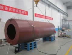
b) Experimental model
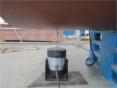
c) Installation of vibration exciter
Fig. 10Sensor arrangement of models
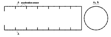
a) Sensor arrangement of Model s1
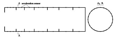
b) Sensor arrangement of Model s2
4.2. Experimental validation
The vibration response of Model s1 and Model s2 was obtained experimentally, and the mean square normal velocity of the cylindrical shell was calculated by Eq. (3), which was compared with the result by the numerical method, as shown in Fig. 11. It can be seen that the experimental and the numerical results were in good line.
Fig. 11Comparison between experimental results and numerical results of mean square velocity
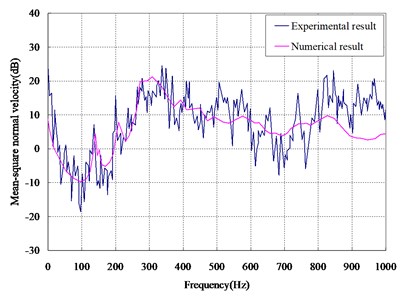
a) Result of Model s1
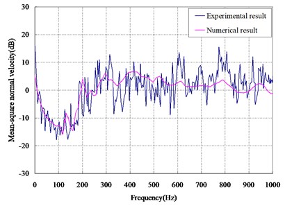
b) Result of Model s2
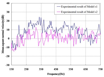
Comparing the experimental results of Model s1 and Model s2, as shown in Fig. 12, it can be seen that in some frequency band (e.g., 220-440 Hz, 460-600 Hz), the aperiodic frame-spacing arrangement can reduce the vibration of the cylindrical shell.
Fig. 12Comparison between experimental results of two models
5. Conclusions
The vibration characteristics of a cylindrical shell with frame aperiodicity were studied in this paper, and the theory of Anderson localization was extended to the frame acoustic design of the cylindrical shell. The frame spacing was designed by the random method. The cylindrical shell with frame aperiodicity was then constructed. The vibration response of the framed cylindrical shell was calculated and compared, and the following conclusions can be drawn:
1) The influence of the form of the frame arrangement on the vibration of the cylindrical shell is shown mainly in the medium-high frequency band, in which the structural wavelength is smaller than the frame spacing. The influence of the form of the frame arrangement on the vibration of the cylindrical shell is not obvious in the low-frequency band.
2) In some frequency bands, the aperiodic arrangement of the frame spacing can decrease the vibration of the cylindrical shell.
3) The method proposed, and the conclusions drawn in this paper can be taken as the basis of further studies of similar problems.
References
-
P. Wang, T. Li, and X. Zhu, “Free flexural vibration of a cylindrical shell horizontally immersed in shallow water using the wave propagation approach,” Ocean Engineering, Vol. 142, pp. 280–291, Sep. 2017, https://doi.org/10.1016/j.oceaneng.2017.07.006
-
C. Pan, X. Sun, and Y. Zhang, “Vibro-acoustic analysis of submerged ring-stiffened cylindrical shells based on a symplectic wave-based method,” Thin-Walled Structures, Vol. 150, p. 106698, May 2020, https://doi.org/10.1016/j.tws.2020.106698
-
W. Jia, M. Chen, Z. Zhou, and K. Xie, “A semi-analytical method for vibro-acoustic analysis of submerged ring-stiffened cylindrical shells coupled with arbitrary inner structures,” Applied Acoustics, Vol. 179, p. 108047, Aug. 2021, https://doi.org/10.1016/j.apacoust.2021.108047
-
K. Zhao, J. Fan, B. Wang, and W. Tang, “Analytical and experimental study of the vibro-acoustic behavior of a semi-submerged finite cylindrical shell,” Journal of Sound and Vibration, Vol. 482, p. 115466, Sep. 2020, https://doi.org/10.1016/j.jsv.2020.115466
-
Z. Lin, K. Zhou, Z. He, Y. Chen, Z. Li, and H. Hua, “Vibro-acoustic analysis of a cylindrical-conical hull subjected to propeller forces,” Applied Ocean Research, Vol. 104, p. 102373, Nov. 2020, https://doi.org/10.1016/j.apor.2020.102373
-
X. Wang, E. Xu, C. Jiang, and W. Wu, “Vibro-acoustic behavior of double-walled cylindrical shells with general boundary conditions,” Ocean Engineering, Vol. 192, No. 15, p. 106529, Nov. 2019, https://doi.org/10.1016/j.oceaneng.2019.106529
-
A. K. Roy and R. Plunkett, “Wave attenuation in periodic structures,” Journal of Sound and Vibration, Vol. 104, No. 3, pp. 395–410, Feb. 1986, https://doi.org/10.1016/0022-460x(86)90297-x
-
M. N. Ichchou, J. Berthaut, and M. Collet, “Multi-mode wave propagation in ribbed plates: part I, wavenumber-space characteristics,” International Journal of Solids and Structures, Vol. 45, No. 5, pp. 1179–1195, Mar. 2008, https://doi.org/10.1016/j.ijsolstr.2007.09.032
-
M. N. Ichchou, J. Berthaut, and M. Collet, “Multi-mode wave propagation in ribbed plates. Part II: Predictions and comparisons,” International Journal of Solids and Structures, Vol. 45, No. 5, pp. 1196–1216, Mar. 2008, https://doi.org/10.1016/j.ijsolstr.2007.08.020
-
K. A. Dickow, J. Brunskog, and M. Ohlrich, “Modal density and modal distribution of bending wave vibration fields in ribbed platesa),” The Journal of the Acoustical Society of America, Vol. 134, No. 4, pp. 2719–2729, Oct. 2013, https://doi.org/10.1121/1.4818889
-
D. M. Mead, “Wave propagation in continuous periodic structures: research contributions from Southampton, 1964-1995,” Journal of Sound and Vibration, Vol. 190, No. 3, pp. 495–524, Feb. 1996, https://doi.org/10.1006/jsvi.1996.0076
-
A. S. Bansal, “Collective and localized modes of mono-coupled multi-span beams with large deterministic disorders,” The Journal of the Acoustical Society of America, Vol. 102, No. 6, pp. 3806–3809, Dec. 1997, https://doi.org/10.1121/1.420406
-
H. H. Hu and J. Shang, “Vibration localization in a fluid-loaded rectangular plate with rib irregularity,” in Applied Mechanics and Materials, Vol. 226-228, pp. 191–194, Nov. 2012, https://doi.org/10.4028/www.scientific.net/amm.226-228.191
-
A. J. Cooper and D. G. Crighton, “Response of irregularly ribbed elastic structures, under fluid loading, to localized excitation,” Proceedings of the Royal Society of London. Series A: Mathematical, Physical and Engineering Sciences, Vol. 455, No. 1983, pp. 1083–1105, Mar. 1999, https://doi.org/10.1098/rspa.1999.0350
-
D. Bouzit and C. Pierre, “Localization of vibration in disordered multi-span beams with damping,” Journal of Sound and Vibration, Vol. 187, No. 4, pp. 625–648, Nov. 1995, https://doi.org/10.1006/jsvi.1995.0549
-
C. H. Hodges, “Confinement of vibration by structural irregularity,” Journal of Sound and Vibration, Vol. 82, No. 3, pp. 411–424, Jun. 1982, https://doi.org/10.1016/s0022-460x(82)80022-9
-
A. S. Bansal, “Flexural waves and deflection mode shapes of periodic and disordered beams,” The Journal of the Acoustical Society of America, Vol. 72, No. 2, pp. 476–481, Aug. 1982, https://doi.org/10.1121/1.388103
-
A. S. Bansal, “Free waves in periodically disordered systems: natural and bounding frequencies of unsymmetric systems and normal mode localization,” Journal of Sound and Vibration, Vol. 207, No. 3, pp. 365–382, Oct. 1997, https://doi.org/10.1006/jsvi.1997.1094
-
D. Bouzit and C. Pierre, “An experimental investigation of vibration localization in disordered multi-span beams,” Journal of Sound and Vibration, Vol. 187, No. 4, pp. 649–669, Nov. 1995, https://doi.org/10.1006/jsvi.1995.0550
-
C. H. Hodges and J. Woodhouse, “Confinement of vibration by one-dimensional disorder, I: Theory of ensemble averaging,” Journal of Sound and Vibration, Vol. 130, No. 2, pp. 237–251, Apr. 1989, https://doi.org/10.1016/0022-460x(89)90552-x
-
C. H. Hodges and J. Woodhouse, “Confinement of vibration by one-dimensional disorder, II: A numerical experiment on different ensemble averages,” Journal of Sound and Vibration, Vol. 130, No. 2, pp. 253–268, Apr. 1989, https://doi.org/10.1016/0022-460x(89)90553-1
-
M. H. Marcus, B. H. Houston, and D. M. Photiadis, “Wave localization on a submerged cylindrical shell with rib aperiodicity,” The Journal of the Acoustical Society of America, Vol. 109, No. 3, pp. 865–869, Mar. 2001, https://doi.org/10.1121/1.1336500
-
L. Maxit and J.-M. Ginoux, “Prediction of the vibro-acoustic behavior of a submerged shell non periodically stiffened by internal frames,” The Journal of the Acoustical Society of America, Vol. 128, No. 1, pp. 137–151, Jul. 2010, https://doi.org/10.1121/1.3436526
-
L. Wenxi, G. Huiren, Z. Qidou, and L. Jingjun, “Study on structural-acoustic characteristics of cylindrical shell based on wavenumber spectrum analysis method,” Brodogradnja, Vol. 72, No. 2, pp. 57–71, Jun. 2021, https://doi.org/10.21278/brod72204
-
D. M. Photiadis, “Localization of helical flexural waves by irregularity,” The Journal of the Acoustical Society of America, Vol. 96, No. 4, pp. 2291–2301, Oct. 1994, https://doi.org/10.1121/1.410101
-
W. X. Liu and Q. D. Zhou, “Study on characteristics of acoustic radiation from the cabin structure with nonuniform subdivision,” (in Chinese), Journal of Ship Mechanics, Vol. 20, No. 8, pp. 1045–1058, 2016, https://doi.org/10.3969/j.issn.1007-7294.2016.08.014
About this article

This research was funded by the National Natural Science Foundation of China (Grant No. 52071334).
