Abstract
This paper studies the transient process of synchronous generator after three-phase short circuit, deduces the expression of stator current in the transient process of synchronous generator, and verifies the theoretical conclusion through simulation. After the short circuit occurs, the electromagnetic transient process is complex. In the electromagnetic transient process, the stator current and rotor current of synchronous generator appear attenuation oscillation due to direct-axis reactance, cross-axis reactance, transient reactance and sub-transient reactance. Based on the basic principle of synchronous generator, this paper analyzes the analytical expressions of stator straight axis current, stator cross axis current and total current. After that, the simulation model is built in Matlab/Simulink, and the simulation results are consistent with the theoretical analysis results. This simulation method provides convenience for analyzing the transient process of synchronous generator and has good engineering application value.
Highlights
- The research method of the transient process of three-phase short-circuit fault of synchronous generator is proposed.
- Analytical expression and Matlab/Simulink were used to simulate the transient process, and the characteristics of the transient process were discussed.
- The results show that the method proposed in this paper can accurately simulate the transient process of three-phase short circuit of synchronous generator, which lays a foundation for the parameter d
1. Introduction
Synchronous generator is the core equipment of modern power system. In the event of three-phase short-circuit fault, the transient process of synchronous generator has an important influence on the safe operation and protection of synchronous generator [1]. After the large disturbance of the power system, the synchronous generator experiences the electromagnetic transient process and the electromechanical transient process. This paper studies the electromagnetic transient process of the synchronous generator [2]. The variation of terminal voltage, stator current, excitation current, power angle and rotational speed of synchronous generator need to be studied in electromagnetic transient process. A synchronous generator model is built in MATLAB/Simulink simulation environment. It is important to study the protection device of generator that studies the voltage and current change of synchronous generator in three-phase short-circuit fault.
2. Three-phase short circuit analysis of synchronous generator
When discussing the three-phase short circuit of synchronous generator, the normal operation and fault operation state of synchronous generator can be superimposed and solved [3, 4]. This is equivalent to adding a three-phase voltage equal to and reverse to the generator terminal voltage in normal operation of the generator at the generator port. After adding three-phase voltage at both ends of the stator winding, in order to keep the flux chain of the winding unchanged, an instantaneous current is produced in the stator winding. The decay of these currents is as follows, the DC and frequency doubling components of the stator attenuate to zero at the moment of short circuit, and the AC component of the stator gradually attenuates from the initial value and finally attenuates to the steady value. In addition, most of the rotor current will decay to zero, leaving only the rotor DC.
As time goes by, the free current that appears in the short-circuit state will decay to zero due to the resistance of the stator and rotor. The time constant will determine the attenuation of the current components of each winding. The larger the time constant, the slower the attenuation, and the smaller the time constant, the faster the attenuation. in synchronous generator, there are windings on stator and rotor, and the time constant of winding is related to inductance, then the time constant is expressed as the ratio of winding inductance value to winding resistance. The transient differential equation of winding is explained by the negative number of the ratio of winding resistance to winding inductance, that is, the characteristic root of differential equation [5]. When magnetic coupling exists in adjacent windings, mutual inductance should be considered to calculate the time constant, otherwise it will affect the accuracy of the final result. Under the circumstance of ensuring the constant flux linkage, studying the free current generated during short circuit, it can be concluded that according to the rotor excitation time constant Td’, it can be concluded that it attenuates according to the time constant of excitation winding which the DC and frequency doubling components of stator windings correspond to the fundamental frequency components of rotor current [6]. The time constant 9 is determined by the ratio of inductance of stator winding to resistance considering the mutual inductance of excitation winding [7, 8]. When this magnetic flux passes through the longitudinal axis of the rotor, the equivalent reactance of the stator winding is ; when it passes through the horizontal axis, it is . The calculation process of the stator and rotor current is as follows, the , axis component of stator current is calculated first, and then the rotor current is calculated by the integration of formula.
The -axis component of the stator current is:
The -axis component of the stator current is:
Through the finishing transformation of the above formula, the current in the rotor winding can be obtained as show in Eq. (3):
a phase current of stator is:
where is the synchronous reactance of stator winding straight axis (longitudinal axis); is the synchronous reactance of stator winding cross axis (transverse axis); is the armature reaction reactance between the longitudinal axis windings; is the reactance of the longitudinal axis of the generator rotor; is the reactance of the horizontal axis of the generator rotor; , represent the reactance of d and q damper windings; is the transient reactance of longitudinal axis; is the secondary transient reactance on the longitudinal axis; is the secondary transient reactance of the longitudinal axis; is the transient electromotive force of the transverse axis; is the secondary transient electromotive force of the transverse axis; is the transient electromotive force of longitudinal axis; is the instantaneous no-load electromotive force before short circuit; is the terminal voltage before short circuit.
3. Three-phase short circuit simulation of synchronous generator
3.1. Three-phase short-circuit model of synchronous generator
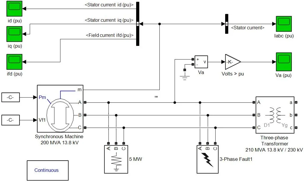
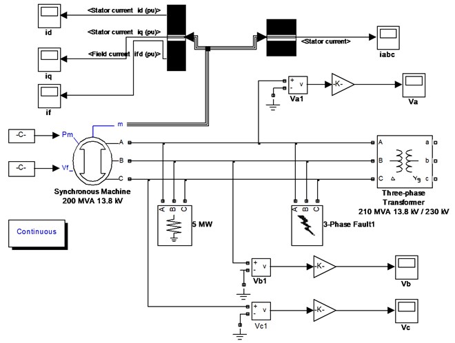
A three-phase short-circuit simulation model of synchronous generator is established in Matlab/Simulink simulation environment. The model is shown in Fig. 1.
Fig. 1the Simulation model of three-phase short-circuit of synchronous generator
3.2. Parameter setting of simulation model
The basic parameters of the synchronous generator are as follows: rated power is 200 MW, 13.8 kV, 50 HZ, 1.0, 0.3, 0.21, 0.6, 0.31, 0.15, 1.64 s, 0.34 s, 1.4 s, 0.005.
The simulation model is established and the simulation parameters are modified. Through the Powergui module, the fault time is set to 0.02025 s, the simulation step is 0.01 s, the simulation time is set to 1 s, and the ode23tb algorithm is selected to solve the problem.
3.3. Analysis of simulation results
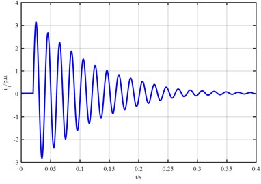
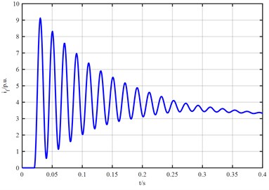
The waveform of stator direct-axis current of synchronous generator is shown in Fig. 2. It can be seen from Fig. 2 that the stator direct-axis current increases sharply at the moment of three-phase short circuit of synchronous generator and the maximum current amplitude is 9 p.u., After reaching the maximum current, the amplitude attenuates rapidly with time constant and finally attenuates to 0 p.u. The waveform of stator cross-axis current in Fig. 3 shows that when three-phase short circuit occurs in three-phase fault device, the stator cross-axis current increases rapidly to the current amplitude, the maximum current is 3.02 p.u., then rapidly attenuates up and down to zero value, and the stator cross-axis current attenuates to 0 p.u. due to resistance.
Fig. 2The waveform diagram of stator straight axis current
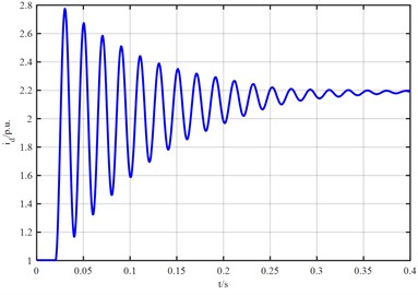
Fig. 3The waveform of stator cross-axis current
The waveform of the excitation current is shown in Fig. 4. At the moment of short circuit of synchronous generator, the excitation current does not decay for a period of time after the fault, and increases rapidly to the current standard value of 2.8, which is due to the attenuation of damping winding current. In order to maintain the flux conservation, the excitation winding increases the current, and the excitation current continues to decay after increasing to the amplitude, but it will not attenuate to 0.
Fig. 4The waveform diagram of excitation current if
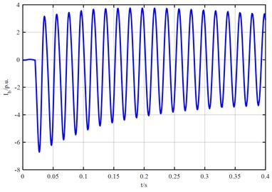
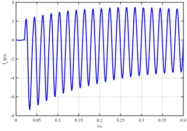
The three-phase current waveform of stator when synchronous generator is short-circuited is shown in Fig. 5. The amplitude of the three-phase waveform is equal and the phase difference is 120 degrees before the failure. In the event of a three-phase short circuit fault, the a phase current waveform first moves to the coordinate axis the positive half axis, then gradually moves to the coordinate axis the negative half axis. The moving direction of b phase and c phase is opposite to that of a phase. The three-phase amplitude is equal, the phase difference is still 120 degrees, and the stator three-phase current finally attenuates to the steady-state value.
Fig. 5The simulation waveform of stator current ia, ib, ic during three-phase short circuit of synchronous generator
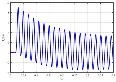
It can be seen from the above analysis that when the synchronous generator is operating normally, there is no direct-axis and quadrature-axis currents. At the moment of short circuit, the vertical axis and horizontal axis currents gradually increase, and decay after a period of time after short circuit. The direct axis current increases faster than the quadrature axis current, and the attenuation is also slower than the quadrature axis. At the same time, the excitation current not only does not attenuate but increases sharply after short circuit. The main result is that the DC current attenuates quickly. The excitation winding attenuates the DC current and increases the excitation current to offset the attenuation of the DC current, thus maintaining the flux conservation. At the moment of short circuit of synchronous generator, stator current contains three components: fundamental frequency, DC frequency and frequency doubling component. When a three-phase short-circuit fault occurs, the A phase current increases the waveform first and then gradually moves down because of attenuation, while the B, C phase current waveform is opposite to the A phase current. The amplitude of the three-phase current is equal, the phase difference is invariant, The stator three-phase voltage decays directly to zero from the value before the short-circuit moment. In general, the three-phase short circuit of synchronous generator has an effect on the voltage and current, which makes the voltage drop to zero directly. For the current, the process is more complicated, but the total current is increased.
4. Conclusions
The proposed simulation model is convenient to modify various reactance parameters and time constants of the synchronous generator, and can accurately simulate the electromagnetic transient process of the synchronous generator. The expressions of stator current and rotor current of synchronous generator are given, which lay a foundation for further research on the influence of various reactance on short-circuit current.
References
-
Best R. J., Morrow D. J., Crossley P. A. Current transients in the small salient-pole alternator during sudden short-circuit and synchronisation events. IET Electric Power Applications, Vol. 4, Issue 9, 2010, p. 687-700.
-
Zhao L., Feng Y. Simulation and analysis of short circuit in 1000 MW synchronous generator based on Simulink/SPS module. Asia-Pacific Power and Energy Engineering Conference, 2010.
-
Spunei E., Piroi I. Comparative analysis between stationary and dynamic parameters of a synchronous generator, with the main variable of the air gap magnetic induction. International Conference on Applied and Theoretical Electricity, 2012.
-
Wang J. X., Zobaa A. F., Bie Z. H., et al. From mathematical analysis to experimental calculation: teaching three-phase short-circuits of a synchronous generator. International Journal of Electrical Engineering Education, Vol. 49, Issue 4, 2012, p. 444-463.
-
Sohn J., Hong S., Sunwoo M. Alternator torque model based on equivalent circuit of synchronous generator for electric power management. IEEE Transactions on Vehicular Technology, Vol. 62, Issue 8, 2013, p. 3593-3602.
-
Piroi I., Elisabeta S., Piroi F. Experimental measurements of the rotor oscillations in an synchronous generator during the three-phased sudden short-circuit test. International Conference on Applied and Theoretical Electricity, 2014.
-
Zhu Y. N., Jin J. X. Simulation analysis of a synchronous generator system under fault conditions. International Conference on Applied Superconductivity and Electromagnetic Devices, 2013, p. 180-184.
-
Hackbart M. Novel approach to calculate electrical currents in stator-, field- and damper-windings at three-phase sudden short-circuit for large synchronous generators. Elektrotechnik Und Informationstechnik, Vol. 133, Issue 2, 2016, p. 112-120.
About this article

This paper was supported by the following research projects: by the Natural Science Fund of Fujian Province (2019 J01845).
