Abstract
In order to accelerate the process of building industrialization, improve the overall stability and construction quality of the building. In this paper, a bolted connection method is designed to study the seismic performance of the composite concrete shear wall specimens with horizontal split joints from the aspects of bearing capacity, ductility, energy dissipation, deformation capacity and failure mode. The test results show that the bolted concrete shear wall is feasible and the connectors can effectively connect the upper and lower precast shear walls to form a whole with certain lateral stiffness. The energy dissipation capacity of the specimens is similar to that of other prefabricated concrete shear wall structures with “self-reduction”. The displacement Angle is greater than 1/120 of the limit value of the displacement Angle between elastic-plastic layers under the action of large earthquakes, and the specimen has good deformation capacity. The energy dissipation capacity of the structure from dynamics perspective reveals that smaller capacity of the specimen by providing energy dissipation factor 0.24 and equivalent viscous damping coefficient of 0.038.
Highlights
- A bolted connection method is designed to study the seismic performance of the composite concrete shear wall specimens with horizontal split joints from the aspects of bearing capacity and ductility.
- The bolted concrete shear wall is feasible and the connectors can effectively connect the upper and lower precast shear walls to form a whole with certain lateral stiffness.
- The energy dissipation capacity of the specimens is similar to that of other refabricated concrete shear wall structures with "self-reduction".
1. Introduction
Prefabricated concrete structure (hereinafter referred to as “prefabricated structure”) is a concrete structure formed by assembling and connecting precast concrete members or components. The main stress members and components of the prefabricated structure are manufactured in an industrial way and assembled and connected on site to form the main body of the structure. Compared with the traditional cast-in-place concrete structure, it has the advantages of high industrialization level, fast construction speed, good construction quality, reduction of dust on site and reduction of construction waste, etc., which can improve the construction quality and production efficiency, reduce the construction cost, and effectively realize the green development requirements of “four sections and one environmental protection” [1]. The development of prefabricated buildings is a major change in the way of construction. Compared with the traditional construction method, the main parts of prefabricated building, such as precast concrete composite floor, wall board, beam and column, staircase and balcony, are all prefabricated in the form of factory, which is easy to carry out quality control. In the field construction, the traditional secondary structure, plastering, external insulation and other procedures are cancelled due to the use of prefabricated components, which saves the construction period and reduces dust pollution at the same time. Reduce construction waste by 80 %; Mechanized operation is adopted on a large scale to save manpower; A large number of prefabricated components are adopted to reduce the use of formwork on the construction site and reduce wet operation. Prefabricated buildings have the characteristics of high degree of industrialization, fast construction speed and good economy [2]. The products mentioned above shall be manufactured separately in the factory according to the requirements of architectural design, and the factory operation shall be implemented. After the relevant components are manufactured, they are transported to the construction site and assembled and connected to form a building that meets the predetermined functional requirements. Compared with traditional construction methods, the most prominent characteristics of industrial buildings are embodied in five aspects: standardization of design, factory-based production of structures and fittings, construction and assembly, integration of decoration and management informatization, which can significantly improve construction efficiency, save construction costs and improve the working environment.
In the present prefabricated concrete structure, the prefabricated concrete shear wall structure takes up a large proportion. Due to the existence of horizontal and vertical split joints in production and construction modes, the horizontal split joints mainly transfer the vertical load between the upper and lower precast shear walls and bear the horizontal wall shear, while the vertical split joints transfer the interaction between adjacent precast shear walls. Scholars at home and abroad have done a lot of research on the assembled shear wall structure. The results show that the performance of the assembled shear wall has a direct impact on the seismic performance of the structure. Researchers of the vertical reinforced with pulp sleeve anchor hole grouting anchor indirect connection and staying lap of precast reinforced concrete shear wall seismic performance test, the results show that adopt wet connection prefabricated shear wall structure bearing capacity, stiffness and seismic performance of basic and cast-in-situ concrete shear wall is the same, can meet the requirements of cast-in-situ “equivalent”, design method of cast-in-situ concrete shear walls can be used for design. These connection technologies have been included in China’s Technical Regulations for Prefabricated Concrete Structures (JGJ1-2014). Among them, the wet connection mode has some problems, such as: the construction technology of wet operation on site is complex and there is no mature method to detect the construction quality [3]; The overall assembly rate cannot be improved, the setting of post-pouring belt cannot effectively shorten the construction period, etc., and the advantages of prefabricated structure cannot be given full play. Therefore, when used for low, multi-story buildings, the construction can be more convenient dry connection. Dry connection refers to the combination of welding and bolted connections embedded in the prefabricated components to complete the overall structure. Compared with the wet connection, the dry connection has the advantages of convenient construction, reducing the wet operation on site, greatly improving the construction efficiency, and the construction quality and precision requirements can be greatly improved.
Considering the complex configuration of steel members, sheathing boards and screw connections, fully scale cyclic loading tests were utilized for the investigation of shear walls performance [4-9]. These tests provide the evidences that the main reason for failure in terms of shear is fastener connections between the framing members and sheathings [10-13]; however, this type of failure commonly occur near the walls and the seams which is indicated as bearing failure of wallboards [14-16].
1.1. Contribution
At present, the connection setting and joint design methods of dry connected prefabricated concrete structures in China are not mature enough, and there are still some problems that need to be solved urgently, such as not being very clear compared with the seismic performance of wet connected prefabricated concrete structures. Therefore, it is of great value and practical significance to study the seismic performance of dry connection prefabricated shear wall in China for the enrichment of the types of prefabricated shear wall connections and for the construction of small and medium-sized urban and rural residential buildings and the promotion of residential industrialization in China. This paper provides the seismic performance of the composite concrete shear wall specimens with horizontal split joints from the aspects of bearing capacity, ductility, energy dissipation, deformation capacity and failure mode.
1.2. Organization
The rest of this paper is organized as: Section 2 presents the state-of-the-art literature survey of the existing techniques in this field; the test preparation is discussed in Section 3 followed by results and analysis in Section 4. Section 5 presents the conclusion and future perspective of this work.
2. Literature review
At present, researchers at home and abroad have made a lot of efforts on the seismic performance of dry coupled prefabricated shear walls. For example, Zhai, X. et al. built the FINITE element model of each specimen using OpenSEES software. The test data verified the accuracy and practicability of the finite element model. Based on the finite element model, the factors affecting the seismic performance of precast concrete shear walls were extensively parameterized, including the length of the filled wall, the concrete strength, the longitudinal reinforcement ratio of the wall limb and the axial compression ratio. Finally, the optimization scheme of prefabricated shear wall with open fill based on the thickness of polystyrene sandwich plate and steel mesh is studied. The test results show that HTCI and PPSCI infilled precast monolithic shear walls fail due to the joint action of bending moment and shear force. The overall shear wall and the ceramsite concrete-filled shear wall have better shear bearing capacity, stiffness, energy dissipation capacity and reliable seismic performance compared with the overall shear wall and the ceramsite concrete-filled shear wall without filling wall, masonry and light diaphragms [17]. Zhang, J. W. et al. conducted quasi-static tests relative to a series of specimens in order to study the low-level restoring force model with single-layer reinforcement and concrete shear wall reinforcement. Based on fitting experimental data and theoretical analysis, the restoring force model considers four characteristic points (crack point, yield point, peak point and fault point) and unloading stiffness degradation. The hysteresis rule of the restoring force model is analyzed by the characteristics of the hysteresis curve for cyclic load tests. The results show that the model of the restoring force skeleton curve and the hysteretic curve are in good agreement with the test curve, and can be used as a reference for the elastic-plastic dynamic analysis of the low shear wall. The dynamic performance of the two low shear walls in the shaking table test and the low-rise seismic failure mechanism with single-layer network reinforced concrete shear walls and diagonal bars were also investigated. SAP2000’s study of the dynamic nonlinear simplified model shows that the proposed restoring force model can be used to analyze the elastic and elastic-plastic dynamic responses of low layers and single-layer network reinforced concrete shear walls and diagonal bars [18]. Shen, S. D. et al. used steel plate shear keys to connect the wall limbs and ensure assembly strength and ductility. However, the relative displacement between the prefabricated wall limbs can lead to serious damage to the floor, whereas the wall limbs may be damaged due to the uncoordinated deformation of the floor. For this reason, this paper presents a slit floor with a polystyrene filled slit near the wall limb to increase the independence of limb deformation. The study focuses on the interaction between shear wall limbs and slotted floors. Three reinforced concrete precast shear wall samples with shear keys are designed: (1) one sample without floor; (2) A sample with a conventional floor; (3) A sample with a slit floor. The quasi-static test results show that the traditional floor slab can increase the lateral resistance and stiffness of the specimen while increasing the ductility. In contrast, slotted floor slabs ensure deformation capacity without weakening dry shear walls. Most importantly, the floor is better protected if slots are set to release concentrated deformation [19]. This paper designed a kind of bolt connection with horizontal flat-fell seam prefabricated concrete shear wall specimen pseudo-static test and numerical simulation analysis of two kinds of methods, from the bearing capacity, ductility, energy dissipation and the deformation and failure mode to study the seismic performance, authentication using this type connection mode for prefabricated shear wall structure in our country small and medium-sized urban and rural residents in seismic fortification of its feasible applicability.
The shear strength and other performance parameters of the walls are improved by Wang and Le [20] using a reinforced shear wall of cold-formed steel (RCFS) and concrete-filled rectangular stell tube (CFRST) columns. The conventional shear walls use the fastener-based modelling method. It needs further investigation in the area of RCFS shear walls and therefore, the research is concerned on the effect of shear performance of CFS shear walls [20-23]. A method of grouted connection having corrugated sleeves located at the sides of the cross-sectional columns other than the corners providing better limit state capacity [24]. The suitability of grouted sleeve connections for structures in the seismic regions is investigated by Belleri and Riva [25] which provided the evidences of ductility and the capacity of energy dissipation by the structural members. A combination of connections along with unbonded tendons and bonded steel bars having sleeves was proposed by Ou et al. [26]. This method was effective in transferring the internal stress of the structure ensuring better ductility and energy dissipation. The bonding behavior of spliced sleeves with flexible and inelastic segments was studied by Sayadi et al. [27, 28]. It reveals that for elastic segments, interlock mechanism helps to decrease the bond strength of spliced sleeved and also improves the load-carrying capacity of the beam. Thereby proving the sleeve connections as efficient and strong for mainstream connections [29]. A novel mechanism for column to column connections with detachable slabs have been presented by Hu et al [30] and Nzabonimpa and Hong [31] which are able to pair steel plates connected by high-strength bolts for the transfer of axial load and moment. A hybrid frame method that incorporates the steel core at the joint regions was proposed by Park et al. [32] which allow vertical reinforcements at the vertical splicing regions.
From the previously reported literature, it was revels that the failure of structures in large earthquakes is due to insufficient ductility and accumulated damage at the structure joints [33-35]. Thus, there is a requirement of more reliable splicing connections not only in terms of convenient construction methods but also having better seismic performance along with goof stiffness, strength and ductility [36]; which is the main focus in this work.
3. Test preparation
This section is dedicated to the test preparation and specimen designing based on the literature survey. The analysis of specimen material strength and test loading device and loading scheme description is presented in this section.
3.1. Specimen design
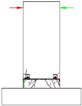
In this test, full scale bolts were used to connect the assembled concrete shear wall specimens, whose wall limb length, width and height were 1200 mm, 200 mm and 2500 mm respectively, and the distance from loading point to the top surface of the foundation was 2600 mm, with a shear span ratio of 2.2. The horizontal and longitudinal rebar distribution in the precast wall panel is 8@200.On the top of the shear wall, there is a loaded beam with a section size of 200 mm×400 mm, which is cast in whole with the precast shear wall. The length, width and height of the foundation beam are 2600 mm, 550 mm and 500 mm respectively [37, 38]. A 300 mm low wall is turned over on the foundation beam and connected to the prefabricated shear wall at this point. Two high-strength screws with a diameter of 16 mm are embedded in the foundation, with a distance of 900 mm and 80 mm from the shear wall edge. The anchorage length of the high-strength screw on the foundation is 480 mm and the exposed length is 100 mm. There are also two connection boxes embedded in the corresponding upper prefabricated wall panel at the same distance of 900 mm.
3.2. Specimen material strength
The designed strength grade of the concrete of the specimen is All C35. At the same time of pouring the concrete specimen, cubic concrete samples with the size of 150 mm×150 mm×150 mm are made. Three test blocks are made for each part of the specimen, and then the specimens are cured under the same conditions. The cube compressive strength of concrete test blocks is actually measured as shown in Table 1.
In the specimen, both the connecting box and connecting plate are made of Q235 steel, all the reinforcement are HRB400, and the high strength screw is made of 45# steel. In the material test of reinforcement, 3 pieces of each kind of reinforcement are selected for tensile test on the universal testing machine according to the test regulations. The test results of steel material are shown in Table 2.
Table 1Concrete material properties test results
Concrete site | Try to block number | Peak force / kN | Cube compressive strength | Mean compressive strength of the cube |
Precast shear wall section | 1 | 342.74 | 34.27 | 36.94 |
2 | 366.36 | 36.64 | ||
3 | 395.99 | 39.60 | ||
Based on the base | 1 | 343.66 | 34.37 | 37.85 |
2 | 409.96 | 41.00 | ||
3 | 381.69 | 38.17 |
Table 2Test results of steel reinforcement
Model | The yield strength | Tensile strength | Elongation |
8 | 524.78 | 663.36 | 20.87 |
10 | 486.08 | 615.17 | 20.74 |
12 | 430.42 | 582.88 | 23.31 |
18 | 425.39 | 585.56 | 22.37 |
20 | 430.88 | 587..23 | 22.82 |
16 | – | 817.88 | – |
3.3. Test loading device and loading scheme
The test is a quasi-static test to study the seismic performance of the bolted coupled concrete shear wall structure under reciprocating horizontal loads. The shear wall was subjected to transverse load at the loading beam by the MTS electro-hydraulic servo actuator. The vertical axial force on the top of the specimen was applied through the hydraulic jack combined with the reaction beam. The support beam and the jack reaction beam were used on both sides of the foundation beam to fix the horizontal displacement. In order to prevent the specimen from out-of-plane instability during loading, lateral restraint protection devices are installed on both sides of the specimen [39]. Lateral restraint is composed of four channel steel, channel steel with steel beam counterforce frame fixed in the laboratory, channel steel end use bolt bearing diameter is 65 mm, bearing surface is smooth, the lateral deformation can occur when rolling deformation in the specimen, thereby reducing the friction influence to test.
The designed axial pressure ratio of the specimen is 0.2. The hydraulic jack and the reaction beam are used to apply the vertical axial pressure on the top of the shear wall loaded beam of 334 kN and 668 kN. The variation of the vertical axial pressure is monitored by the force sensor so as to keep the vertical axial pressure unchanged. The transverse reciprocating load is applied to the specimen at the loading beam through MTS. Before the test is formally loaded, a small lateral load of 10 kN should be applied to the specimen, which should not be greater than 30 % of the cracking load. Observe whether the axial force sensor, strain acquisition instrument and displacement meter are working normally, and if there is no need to timely adjust and check the fault. After the normal operation of all the instruments was established, the test officially began. First, the shear wall specimens were loaded horizontally through MTS, with the force loading speed maintained at 2 kN/s. Only one cycle was needed for each stage of force loading. Observation load - displacement curve of the specimens, the yield curve of turning the specimen after converting the MTS loading system displacement control of load, displacement take specimen yield displacement of shear wall mount point in external gauge measured horizontal displacement, when the level displacement loading cycle twice, after each level displacement according to the yield displacement ratio increase step by step, three times per cycle level; In the displacement loading stage, the horizontal force at the loading point of shear wall is monitored by the MTS system. The test shall be terminated when the bearing capacity of the specimen drops to 85 % of the ultimate bearing capacity. If the bearing capacity of the specimen does not drop to 85 % of the ultimate bearing capacity, the test shall also be terminated if it has been damaged. The test loading system is shown in Fig. 1 and Table 3.
Fig. 1Loading system diagram
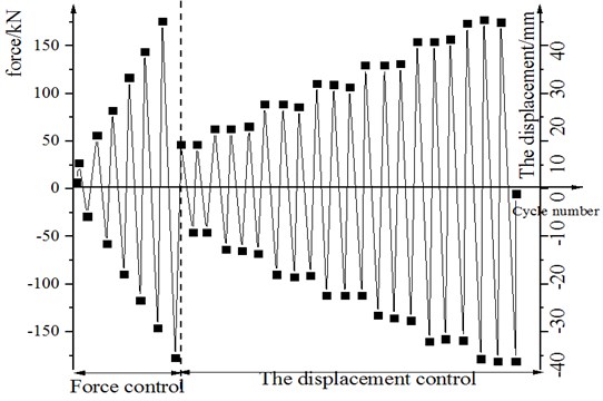
Table 3Specimen loading system
Specimen | Preload (kN) | Force controlled loading (kN) | Displacement controlled loading (mm) |
S-1 | ±10 | ±30, ±60, ±90, ±120 | ±10, ±15 |
S-2 | ±10 | ±30, ±60, ±90, ±120, ±150, ±180 | ±10, ±15, ±20, ±25, ±30, ±35, ±40 |
4. Results and analysis
This section presents the analysis of the results obtained after testing the specimens in terms of various measures. Initially, failure modes of specimens are tested followed by load dissipation hysteresis curve analysis. Then the examination of skeleton curve is done in this section followed by the investigation of bearing capacity, ductility, deformation and energy dissipation capacity.
4.1. Failure modes of specimens
When the horizontal load of the specimen was 120 kN, a small crack appeared at the horizontal split joint between the shear wall and the lower upper over the wall section. According to the horizontal displacement meter at the split joint, there is no obvious shear slip at the split joint position of the shear wall. The strain of vertical reinforcement in shear wall has little change, the strain of high strength screw through horizontal split joint increases slightly faster than that of longitudinal reinforcement of wall, and the bottom plate of connecting box and connecting plate have no deformation [40, 41]. When the horizontal load is 150 kN, the cracks at the horizontal split joint continue to extend from both sides of the wall limb to the neutral axis, and no new cracks appear. At this time, the connecting plate in the connecting box on the right side of the shear wall limb appears a small bending deformation. When the horizontal load is 180 kN, the crack at the horizontal split joint continues to develop and forms the open joint, with the maximum width exceeding 2 mm. The first bending shear oblique crack appears at the upper over the wall section at the lower left of the split seam, as shown in Fig. 2. The crack extends from the syncline below the split seam, with a length of about 60 mm and a maximum width of about 0.28 mm. No. 2 bending shear oblique crack appeared in the parallel place near No. 1 crack, with a length of about 70 mm and a maximum width of about 0.14 mm. In the process of reverse loading, No. 3 oblique crack appears on the upper over the wall section at the lower right of the horizontal split joint of the shear wall. The crack extends from the syncline below the split joint with a length of about 130 mm and a maximum width of about 0.22 mm. At this time, the strain gauge data showed that the high-strength screw near the horizontal split joint did not yield, but the connecting plate in the right connection box produced obvious bending deformation, so the force could not be directly transferred to the high-strength screw. As a result, although the strain of the high-strength screw increased faster than the longitudinal reinforcement of the shear wall, it still did not reach the yield strain. The observed horizontal displacement at the height of the loading point of the shear wall is 10 mm, and the maximum displacement measured by the displacement meter at the horizontal split joint is 1.07 mm. According to the real-time curve recorded by the MTS system, the load-displacement curve of the specimen turns into a displacement-controlled loading stage.
Fig. 2Crack distribution when load is 180 kN
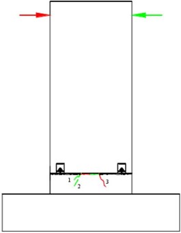
Fig. 3Crack distribution when displacement is 15 mm
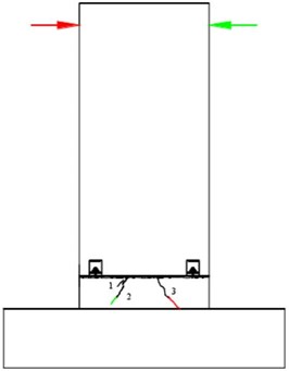
When the vertex displacement is increased to 15 mm, crack No. 3 extends downward to the top surface of the foundation, while other cracks develop to different degrees. The maximum width of Crack No. 1 is 0.3 mm, the maximum width of crack No. 2 is 0.2 mm, and the maximum width of crack No. 3 is 0.7 mm.
The shear slip deformation at horizontal split joints of shear walls is small. When the vertex displacement is added to 30 mm, the horizontal split joint opening width of the shear wall is larger, and the bending deformation of the connecting plate in the connecting box continues to increase. At this time, the energy consumption of the whole shear wall mainly depends on the deformation of the connecting plate in the connecting box, and the reinforcement and high-strength screw in the wall do not yield. A new bending shear oblique crack appears below the split joint of the shear wall, a small crack appears near the left connecting box, and a vertical compression crack appears in the compression zone on both sides of the wall limb below the split joint. The distribution of the crack is shown in Fig. 4. When the peak displacement is increased to 35 mm, the opening degree of shear wall split joints continues to increase, the vertical cracks on both sides of wall limbs below the split joints continue to increase, and the protective layer concrete is gradually peeled off. The crack distribution is shown in Fig. 5. At this time, the bottom plate of the connecting box produces slight bending deformation, and the bending deformation of the connecting plate in the right box is obvious. When the forward peak displacement reaches 34.94 mm, the ultimate bearing capacity of the specimen is 234.72 kN. When the reverse vertex displacement reaches –34.94 mm, the ultimate bearing capacity of the specimen reaches 230.11 kN. When the peak displacement is increased to 40 mm, the crushed area of the wall limb concrete on both sides of the wall limb below the horizontal split joint further increases, and the bearing capacity drops below 85 % of the ultimate load, and the test ends. During the test, no obvious shear slip was observed by the displacement meter at the split joint.
Fig. 4Crack distribution when displacement is 30 mm
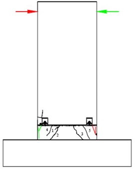
Fig. 5Crack distribution when displacement is 35 mm
4.2. Load-displacement hysteretic curve of specimen
Hysteretic curve is an important basis for determining the restoring force model and nonlinear seismic response analysis. The shape and change of the curve can reflect the deformation characteristics, stiffness degradation and energy consumption of the structure in the process of repeated stress. It is revealed that fuller the curve is, the better is the energy consumption capacity of the structure.
Fig. 6Load-displacement hysteretic curve of specimen
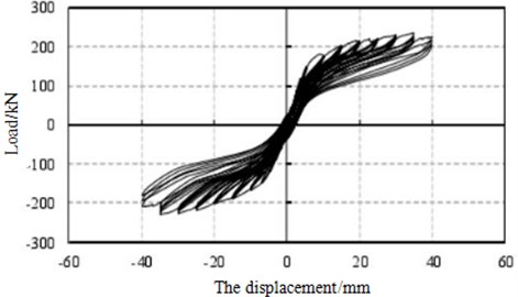
Fig. 6 shows the hysteretic curve of the specimen. It can be seen from the figure that the failure place of the specimen occurs in the connecting plate made of Q235 steel with good deformation capacity, instead of the brittle screw made of high-strength steel, so the specimen has good deformation capacity. However, as mentioned above, because the connecting plate is located above the horizontal split joint of the prefabricated shear wall and the upper over the wall section, the horizontal split joint can still be closed after unloading, and the residual deformation of the specimen is small, although the bending deformation of the connecting plate is large after yielding. Therefore, the hysteresis loop is still very narrow after yielding and the energy dissipation capacity is small. The area of the hysteresis loop was not increased until the concrete was crushed in the compression zone on both sides of the wall under the horizontal split joint, but it was still small overall. The shape of the hysteretic loop is similar to that of other prefabricated concrete structures with “self-resetting” capability, such as those with post-tensioned prestressed bars.
4.3. Skeleton curve
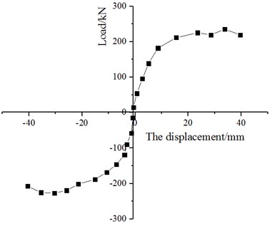
It can be seen from Fig. 7 that the skeleton curve of the specimen can be divided into three stages: when the load is small, it is in the elastic stage, and the load and displacement show a linear relationship. With the increase of load, the connecting plate reaches the yield and enters the elastic-plastic stage.
Obvious inflection point appears on the curve, the deformation growth rate is obviously greater than the load, and the stiffness of the specimen decreases gradually. After the load reaches the peak value, the concrete in the compression zone on the left and right sides of the wall limb below the horizontal split joint is gradually crushed, and the specimen enters the failure stage, with the curve descending.
Fig. 7Skeleton curve of specimen
4.4. Bearing capacity, ductility and deformation capacity
Ductility is a very important control index in seismic design, which reflects the plastic deformation ability of structure or component after yielding. Ductility failure is a kind of obvious deformation failure with premonition. According to different definitions of deformation, ductility coefficient can be divided into curvature ductility coefficient, displacement ductility coefficient and angular ductility coefficient. In this paper, the ductility of specimens is reflected by the displacement ductility coefficient. The cracking, yield, peak value, ultimate load and corresponding displacement and displacement ductility coefficient of specimens during loading are shown in Table 4.
It can be seen from the table that the displacement ductility coefficient of specimens ranged from 3.03 to 3.7 and met the requirements of Code for Seismic Design of Buildings (GB50011-2010) greater than 3.0. The ultimate displacement Angle of the specimen is 1/63, which is larger than the elastic-plastic layer under the seismic design code of buildings. The interval displacement Angle is limited to 1/120, indicating that the specimens have good ultimate deformation and seismic performance, and the bolted connection mode of the specimens can be applied to low and multi-layer fabricated structures. The increase of axial force has an effect on the load and displacement ductility coefficient of each characteristic point.
Table 4Load and displacement ductility coefficient of characteristic points of skeleton curve of specimen
Serial number | The direction of | Cracking point | The yield point | peaks | Limit point | Ductility coefficient | Limiting angle of displacement | ||||
(kN) | (mm) | (kN) | (mm) | (kN) | (mm) | (kN) | (mm) | / | / | ||
S-2 | Positive | 120 | 3.71 | 180.30 | 11.03 | 234.71 | 34.92 | 223.84 | 40.00 | 3.63 | 1/63 |
Reverse | 120 | 4.55 | 182.33 | 13.20 | 230.14 | 34.92 | 209.39 | 40.00 | 3.03 | 1/63 | |
4.5. Energy dissipation capacity
The energy dissipation coefficient and equivalent viscous damping coefficient are important indexes to evaluate the energy dissipation capacity of a structure under the action of reciprocating load. The higher the value, the better the energy dissipation capacity of the structure. Referring to the definition of dissipation coefficient E in Building Seismic Test Code (JGJ/T101-2015), calculation.
Fig. 8Load-deformation hysteretic curve
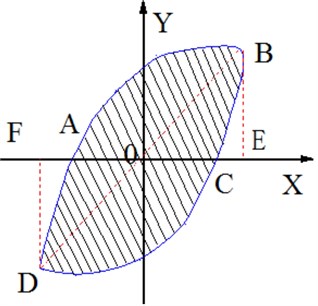
The hysteretic curve of the structure can reflect the energy dissipation capacity of the structure. The fuller the hysteretic curve is, the better the plasticity and toughness are. The stronger the energy dissipation capacity is, the higher the peak point is, and the better the material performance is. The energy dissipation coefficient E is used to represent the hysteretic energy dissipation of each cycle. The larger the value is, the stronger the energy dissipation capacity of the structure is. It can be seen from the loading process that in the elastic stage, the specimen has no plastic deformation inside, the hysteresis loop is almost a straight line with coincidence, and the energy dissipation capacity is weak. In the displacement loading stage, with the development of cracks and the yield of specimens, plastic deformation occurs in the specimens, and the hysteresis loop becomes slightly fuller than before, and the energy dissipation capacity increases. The energy dissipation coefficient of the specimens is shown in Table 5.
Table 5Energy dissipation coefficient of specimens
Load / kN | 30 | 60 | 90 | 120 | 150 | 180 |
0.31 | 0.49 | 0.28 | 0.36 | 0.29 | 0.36 | |
The displacement / mm | 10 | 15 | 20 | 25 | 30 | 35 |
0.18 | 0.25 | 0.28 | 0.26 | 0.25 | 0.24 |
The equivalent viscous damping coefficient is used to evaluate the energy dissipation capacity of the structure from the perspective of dynamics. The energy dissipation coefficient and equivalent viscous damping coefficient of each specimen under peak load are shown in Table 6.
According to the energy dissipation coefficient and equivalent viscosity coefficient, the energy dissipation capacity of the specimen is small.
Table 6Equivalent viscous damping coefficients of specimens
Specimen | Peak load | |
Energy dissipation factor | Equivalent viscous damping coefficient | |
0.24 | 0.038 | |
5. Conclusions
In this paper, a bolted connection mode is designed, and the seismic performance of assembled concrete shear wall specimens with horizontal split joints is studied from the aspects of bearing capacity, ductility, energy dissipation, deformation capacity and failure mode by using two methods of quasi-static test and numerical simulation analysis. The main conclusions are as follows:
1) Test using bolt connection of prefabricated concrete shear wall is feasible, fitting can effectively use upper and lower prefabricated shear wall connected together to form a certain lateral stiffness of the whole, the connection box stiffness is bigger, can effectively transfer the pulling force and shear force, shear wall suffered minor deformation of horizontal connection box bottom a little effects on the flexural bearing capacity of the flat-fell seam.
2) The bending failure and small shear slip occurred in the horizontal split joint of the specimen, indicating that the split joint has a good shear performance. According to the calculation of the current concrete design code, the shear capacity of the horizontal split joint is good, and the increase of axial force has an impact on the shear capacity of the split joint.
3) The specimens had the expected ductility failure and the phenomenon of hysteresis and loop kneading was obvious. The energy dissipation capacity was similar to that of other prefabricated concrete shear wall structures with “self-reduction”, and the overall ductility was good. The displacement Angle is greater than 1/120 of the limit value of the displacement. Angle between elastic-plastic layers under the action of large earthquakes, and the specimen has good deformation capacity. The test provides energy dissipation factor 0.24 and equivalent viscous damping coefficient of 0.038, which is evident of smaller energy dissipation capacity of the specimen.
4) Future perspective of this work will be focused on the improvement of the proposed methods in terms of various aspects to improve the bearing capacity, ductility deformation and energy dissipation capacity of wall structures. Different aspect ratios and multiple wall testing shall be performed in the future to upgrade the shear walls performance.
References
-
Gao W., Li L., Yue Z., Li H., Tong F. Research on the influence of guide blade trailing edge structure on turbine performance. Journal of Thermal Science, Vol. 28, Issue 3, 2019, p. 472-483.
-
Beyzaei M., Hosseininia E. S. A numerical investigation on the performance of the brick stair wall as a supporting structure by considering adjacent building. KSCE journal of civil engineering, Vol. 23, Issue 4, 2019, p. 1513-1521.
-
Gu A., Zhou Y., Xiao Y., Li Q., Qu G. Experimental study and parameter analysis on the seismic performance of self-centering hybrid reinforced concrete shear walls. Soil Dynamics and Earthquake Engineering, Vol. 116, 2019, p. 409-420.
-
Iuorio O., Fiorino L., Landolfo R. Testing CFS structures: The new school BFS in Naples. Thin-Walled Structures, Vol. 84, 2014, p. 275-288.
-
Khaliq W., Moghis A. Shear capacity of cold-formed light-gauge steel framed shear-wall panels with fiber cement board sheathing. International Journal of Steel Structures, Vol. 17, Issue 4, 2017, p. 1404-1414.
-
Landolfo R., Fiorino L., Corte G. D. Seismic behavior of sheathed cold-formed structures: physical tests. Journal of Structural Engineering, Vol. 132, Issue 4, 2006, p. 570-581.
-
Kumar D., Sharma A., Kumar R., Sharma N. A holistic survey on disaster and disruption in optical communication network. Recent Advances in Electrical and Electronic Engineering (Formerly Recent Patents on Electrical and Electronic Engineering), Vol. 13, Issue 2, 2020, p. 130-135.
-
Sharma A., Kumar R. Service-level agreement-energy cooperative quickest ambulance routing for critical healthcare services. Arabian Journal for Science and Engineering, Vol. 44, Issue 4, 2019, p. 3831-3848.
-
Macillo V., Fiorino L., Landolfo R. Seismic response of CFS shear walls sheathed with nailed gypsum panels: experimental tests. Thin-Walled Structures, Vol. 120, 2017, p. 161-171.
-
Sharma A., Kumar R. Risk-energy aware service level agreement assessment for computing quickest path in computer networks. International Journal of Reliability and Safety, Vol. 13, Issues 1-2, 2019, p. 96-124.
-
Tian H. W., Li Y. Q., Yu C. Testing of steel sheathed cold-formed steel trussed shear walls. Thin-Walled Structures, Vol. 94, 2015, p. 280-292.
-
Lin S. H., Pan C. L., Hsu W. T. Monotonic and cyclic loading tests for cold-formed steel wall frames sheathed with calcium silicate board. Thin-Walled Structures, Vol. 74, 2014, p. 49-58.
-
Zeynalian M., Ronagh H. R. Seismic performance of cold formed steel walls sheathed by fibre-cement board panels. Journal of Constructional Steel Research, Vol. 107, 2015, p. 1-11.
-
Baran E., Alica C. Behavior of cold-formed steel wall panels under monotonic horizontal loading. Journal of Constructional Steel Research, Vol. 79, 2012, p. 1-8.
-
Shamim I., DaBreo J., Rogers C. A. Dynamic testing of single-and double-story steel-sheathed cold-formed steel-framed shear walls. Journal of Structural Engineering, Vol. 139, Issue 5, 2013, p. 807-817.
-
Mohebbi S., Mirghaderi R., Farahbod F., Sabbagh A. B. Experimental work on single and double-sided steel sheathed cold-formed steel shear walls for seismic actions. Thin-Walled Structures, Vol. 91, 2015, p. 50-62.
-
Bhalaik S., Sharma A., Kumar R., Sharma N. Performance modeling and analysis of WDM optical networks under wavelength continuity constraint using MILP. Recent Advances in Electrical and Electronic Engineering (Formerly Recent Patents on Electrical and Electronic Engineering), Vol. 13, Issue 2, 2020, p. 203-211.
-
Zhang J. W., Zheng W. B., Cao W. L., Dong H. Y., Li W. D. Seismic behavior of low-rise concrete shear wall with single layer of web reinforcement and inclined rebars: restoring force model. KSCE Journal of Civil Engineering, Vol. 23, Issue 3, 2019, p. 1302-1319.
-
Shen S. D., Cui Y., Pan P., Gong R. H., Miao Q. S., Li W. F. Experimental study of rc prefabricated shear walls with shear keys affected by a slotted floor slab. Journal of Aerospace Engineering, Vol. 32, Issue 3, 2019, https://doi.org/10.1061/(ASCE)AS.1943-5525.0001000
-
Wang X., Ye J. Reversed cyclic performance of cold-formed steel shear walls with reinforced end studs. Journal of Constructional Steel Research, Vol. 113, 2015, p. 28-42.
-
Jian S. M. H. Z. S., Lin Q. Y. S. Experimental study of the shearing behavior of cold-formed steel wall panels under cyclic load. China Civil Engineering Journal, Vol. 44, Issue 8, 2011, p. 42-51.
-
Salenikovich A. J., Dolan D. J., Easterling S. W. Racking performance of long steel-frame shear walls. International Specialty Conference on Cold-Formed Steel Structures, 2000.
-
Zuyan L. Y. L. F. S., Huiwen H. Experimental investigation on seismic behavior of S350 light-gauge composite framing walls. China Civil Engineering Journal, Vol. 12, 2012, p. 10.
-
Tullini N., Minghini F. Grouted sleeve connections used in precast reinforced concrete construction – experimental investigation of a column-to-column joint. Engineering Structures, Vol. 127, 2016, p. 784-803.
-
Belleri A., Riva P. Seismic performance and retrofit of precast concrete grouted sleeve connections. PCI Journal, Vol. 57, 2012, p. 97-109.
-
Ou Y.-C., Wang P.-H., Tsai M.-S., Chang K.-C., Lee G. C. Large-scale experimental study of precast segmental unbonded posttensioned concrete bridge columns for seismic regions. Journal of Structural Engineering, Vol. 136, Issue 3, 2009, p. 255-264.
-
Sayadi A. A., Rahman A. B. A., Jumaat M. Z. B., Alengaram U. J., Ahmad S. The relationship between interlocking mechanism and bond strength in elastic and inelastic segment of splice sleeve. Construction and Building Materials, Vol. 55, 2014, p. 227-237.
-
Sayadi A. A., Rahman A. B. A., Sayadi A., Bahmani M., Shahryari L. Effective of elastic and inelastic zone on behavior of glass fiber reinforced polymer splice sleeve. Construction and Building Materials, Vol. 80, 2015, p. 38-47.
-
Wu D., Liang S., Guo Z., Zhu X., Fu Q. The development and experimental test of a new pore-forming grouted precast shear wall connector. KSCE Journal of Civil Engineering, Vol. 20, Issue 4, 2016, p. 1462-1472.
-
Hu J. Y., Hong W. K., Park S. C. Experimental investigation of precast concrete based dry mechanical column-column joints for precast concrete frames. The Structural Design of Tall and Special Buildings, Vol. 26, Issue 5, 2017, p. e1337.
-
Nzabonimpa J., Hong W. K. Structural performance of detachable precast composite column joints with mechanical metal plates. Engineering Structures, Vol. 160, 2018, p. 366-382.
-
Park S. C., Hong W. K., Kim S., Wang X. Mathematical model of hybrid precast gravity frames for smart construction and engineering. Mathematical Problems in Engineering, Vol. 2014, 2014, p. 916951.
-
Mitchell D., Devall R. H., Saatcioglu M., Simpson R., Tinawi R., Tremblay R. Damage to concrete structures due to the 1994 Northridge earthquake. Canadian Journal of Civil Engineering, Vol. 22, Issue 2, 1995, p. 361-377.
-
Gulkan P. The Ceyhan-Misis earthquake of 27 June 1998: A Preliminary Engineering Reconnaissance Report. Implementation and Research Center, Ankara, 1998.
-
Park R. Seismic design and construction of precast concrete buildings in New Zealand. PCI Journal, Vol. 47, Issue 5, 2002, p. 60-75.
-
Choi H.-K., Choi Y.-C., Choi C.-S. Development and testing of precast concrete beam-to-column connections. Engineering Structures, Vol. 56, 2013, p. 1820-1835.
-
Hou H., Fu W., Qiu C., Cheng J., Qu Z., Zhu W., et al. Effect of axial compression ratio on concrete-filled steel tube composite shear wall. Advances in Structural Engineering, Vol. 22, Issue 3, 2019, p. 656-669.
-
Wang L., Xue Y., Wang C., Lu X. Seismic performance of flat plate structure with steel capital. ACI Structural Journal, Vol. 116, Issue 2, 2019, p. 221-232.
-
Keunyeong O., Heonjun H., Byeonghyeon J., Kangmin L. An analytical study on structural performance evaluation of coupled steel plate shear wall systems. International Journal of Steel Structures, Vol. 19, Issue 1, 2018, p. 1-13.
-
Li L. Z., Liu X., Yu J. T., Lu Z. D., Su M. N., Liao J. H., et al. Experimental study on seismic performance of post-fire reinforced concrete frames. Engineering Structures, Vol. 179, 2019, p. 161-173.
-
Liu X. C., Cui F. Y., Zhan X. X., Yu C., Jiang Z. Q. Seismic performance of bolted connection of h-beam to hss-column with web end-plate. Journal of Constructional Steel Research, Vol. 156, 2019, p. 167-181.
Cited by
About this article

