Abstract
Aiming at the lack of timely and effective evaluation of knee anterior cruciate ligament (ACL) reconstruction, a knee ACL force and displacement measuring instrument was developed. Test experiments were carried out using a laboratory-made test platform and a robotic arm. Firstly, the importance of anterior cruciate ligament reconstruction surgery is introduced. The necessity of this kind of measuring instrument is proposed. The reliability of the lower stiffness measuring instrument under different measurement conditions in space is verified by the mechanical model of the previous ACL in-situ measurement. Then the design structure and measurement system of the instrument are introduced in detail. Finally, using the laboratory-made test platform and the UR5 robot arm and stiffness measuring instrument for the displacement and force test accuracy experiments, and the pig bone anterior cruciate ligament test and postoperative evaluation experiments, prove that the measuring instrument can be used for ACL Assessment of reconstructive surgery.
Highlights
- Realize the measurement of the bio-stiffness of the anterior cruciate
- Achieve measurement at any angle in space
- Auxiliary doctors complete the evaluation of ACL reconstruction surgery
- The force measuring instrument system has the advantages of small hardware, low power consumption, high reliability and high rigidity.
1. Introduction
The knee joint plays an important role in the upright, walking and jumping of the human body. The structure needs good stability and flexibility. The knee cruciate ligament is an important part of the ligament joint capsule network. It plays a role in connecting the lower end of the femur and the upper end of the humerus [1]. It has the function of restricting the movement of the anterior and posterior tibia. It is often in the passive traction state when the knee joint is flexed and stretched. It is prone to damage and may cause damage to related structures in the joint, resulting in decreased joint stability, thereby accelerating the lesions of the entire joint. At present, with the increasing number of sports injuries and traffic injuries, the incidence of anterior cruciate ligament injury is increasing. ACL transplantation reconstruction is currently the main treatment for ACL injury. Arthroscopic reconstruction has been widely accepted at home and abroad in the past decade. However, ACL navigation surgery still has 8 % to 25 % of unsuccessful cases [2-4], and doctors after reconstruction surgery The ligament assessment is derived from the patient's subjective perception, joint stability test, and postoperative X-ray or CT fluoroscopy, which is not very accurate and lacks authenticity [5].
In view of the above problems, combined with the real environment of the knee joint, this paper designed a mechanical property testing instrument for the ligament reconstruction of the knee joint ACL reconstruction, and used the mechanical model proposed by the laboratory to verify the function of the instrument [6].
2. Introduction to experimental methods
The platform of the previous work experiment realized the lateral force tensile test on the ACL two-dimensional plane level, and proposed a method for measuring the lateral force of the ligament laterally on the basis of the existing. As shown, the laboratory lateral ligament lateral force stretching platform, ligament tensile instrument, and UR5 robot were used to measure the spatial lateral force of the ligament after ACL reconstruction.
3. Measuring instrument design
The measuring instrument designed in this paper is fixed at the end of the UR robot. The whole structure is shown in the figure. The knee measuring instrument system is mainly divided into three parts: mechanism, control system and power supply. Its main function is to realize the movement of the machine in the designed 2 degrees of freedom, collect and analyze the force deformation data of the ACL after surgery, and complete the surgical evaluation.
3.1. Structural design of measuring instruments
The structure of the measuring instrument is 2 degrees of freedom structure, and the joint configuration adopts the rectangular coordinate structure of PR. It has the characteristics of high structural rigidity, independent joint motion, no coupling, and simple kinematics solution. From the perspective of function and economy, the structure uses a miniature harmonic deceleration stepping motor, which has the advantages of small size, large torque and high precision. The system consists of a stretching mechanism, a torsion mechanism, a force and a displacement collecting mechanism. The stretching mechanism is a micro-one-dimensional servo platform, which is composed of a bottom plate, a linear guide, a slider, a nut seat, a screw, a nut, a coupling, an angular contact ball bearing, a bearing seat, a stepping motor and a motor seat. The torsion mechanism is composed of a motor base, a stepping motor, a coupling, a sleeve, a tensile shaft, and a half structure. The force collecting mechanism is composed of a force sensor, a sensor seat and a torsion mechanism box. The displacement collecting mechanism is composed of a nut seat and a displacement sensor. The measuring instrument system is shown in the Fig. 1.
Fig. 1Stiffness measuring instrument structure
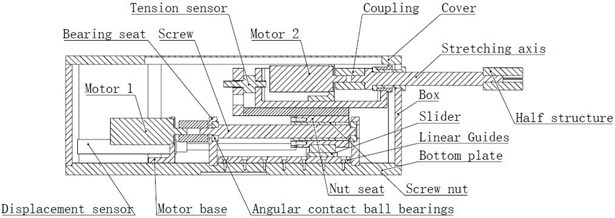
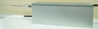
Fig. 2Stiffness measuring instrument physical map
As shown in the Fig. 2, the entire system is dual degrees of freedom (moving and rotational degrees of freedom), both of which are driven by stepper motors for horizontal feed motion and rotary motion. The movement of the slider is limited to the high-precision linear guide. In the horizontal direction, the stepper motor drives the lead screw to make the nut move forward and backward. The rotary motion mechanism as a whole is fed back and forth along with the nut seat. The force sensor is mounted on the sensor base at one end and connected to the outer casing of the rotating mechanism at the other end to detect the pressure feedback when the hook is touched by the ACL. The displacement sensor is mounted horizontally on the base plate parallel to the axial direction of the lead screw. The ejector rod of the displacement sensor is in horizontal contact with the nut seat, and the amount of lateral deformation of the ACL can be obtained by the amount of telescopic feedback of the ejector rod during stretching. The rotary motion mechanism is directly rotated by the stepping motor through the coupling to apply the torque to the ACL ligament for the tensile test of the ACL ligament at different torsion angles.
3.2. Control system design
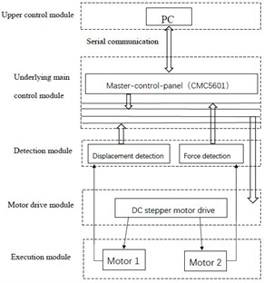
The control system of the measuring instrument is composed of motion controller, drive controller, AD conversion module and signal amplifier. The system design meets the requirements of low power consumption and anti-interference. The control system can be subdivided into six modules: master control, detection, communication, drive, execution, and host computer interaction. As shown in the Fig. 3.
The control module is mainly composed of embedded motion control board, which undertakes the calculation work of instrument operation, including position detection signal reading, communication, decision making, overall control, etc. It obtains environmental information from the detection system, then performs decision operations and sends control data to the execution system. The detection module is divided into a displacement detection module and a force detection module, which is mainly for position detection. The nut holder is directly in contact with the ejector rod of the displacement sensor, and the length of the resistance strain gauge of the sensor is changed, and the displacement is calculated by the return voltage value, and the measurement precision is 0.01 mm. The human-computer interaction module developed the upper computer control interface with C#. The communication module is composed of serial communication, and RS232 serial communication is used to realize information transmission between the host computer and the embedded motion control board.
Fig. 3Control system: a) Control system diagram, b) the user interface of upper computer control
a)
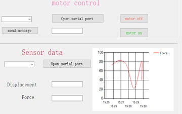
b)
4. ACL lateral pull model (plan test) that references previous work
In the previous experimental work, a mathematical model of postoperative ligament reconstruction based on ACL was proposed [6]. The premise of this model is that the ligament is in the position measurement state, and the pulling direction is in the same plane as the ligament fixing direction. The model parameters are the preload force ( at the beginning of the experiment, the initial length of the ligament (, the cross-sectional area (, the elastic modulus (, ligament stretch () and the required lateral tensile force of the ligament (. In this experiment, it is assumed that the tensile three-dimensional angle has little effect on the biomechanical properties of the ligament stretching to verify the design of the stiffness measuring instrument:
5. Analysis of experimental results
5.1. Displacement accuracy experiment
The horizontal direction control command is respectively sent on the user interface to verify whether the stiffness measuring instrument can run according to the command, and whether the corresponding motion precision and repeated motion precision can be achieved. The horizontal displacement accuracy experiment uses the displacement sensor voltage analog quantity to return the corresponding actual value, and then subtracts the expected value to obtain the accuracy error. The effective stroke in the horizontal direction is 50 mm. Displacement accuracy experiment results as shown in Table 1. The experimental results show that the forward motion accuracy of the displacement platform is 0.05 mm, and the backward motion accuracy is 0.05 mm. It is verified that the motion accuracy can meet the accuracy requirements of the ACL deformation test.
Table 1Displacement accuracy experiment
1 | 2 | 3 | 4 | 5 | 6 | 7 | 8 | Results | |
Advancement / mm | 0.05 | 0.07 | 0.06 | 0.05 | 0.05 | 0.05 | 0.05 | 0.06 | 0.05 |
Back / mm | 0.06 | 0.08 | 0.06 | 0.07 | 0.05 | 0.05 | 0.05 | 0.05 | 0.05 |
5.2. Tensile accuracy experiment
After calibration, the weight values are tested by applying weights of different weights. The test data is shown in Table 2. (Gravity acceleration is 9.8 m/s2)It can be seen from Table 2 that the pressure test accuracy of the platform is 0.33 N, which can meet the accuracy requirements.
Table 2Force measurement accuracy experiment (:N)
1 | 2 | 3 | 4 | 5 | 6 | 7 | 8 | 9 | 10 | 11 | |
Quality / kg | 0 | 0.05 | 0.1 | 0.5 | 1 | 2.5 | 3.5 | 4.5 | 5.5 | 6.5 | 7.5 |
Gravity / N | 0 | 0.49 | 0.98 | 4.9 | 9.8 | 24.5 | 34.3 | 44.1 | 53.9 | 63.7 | 73.5 |
Measurements / N | 0 | 1.5 | 2.3 | 5.1 | 7.4 | 22.3 | 34.3 | 45.9 | 53.9 | 63.7 | 72.9 |
5.3. ACL space lateral force experiment
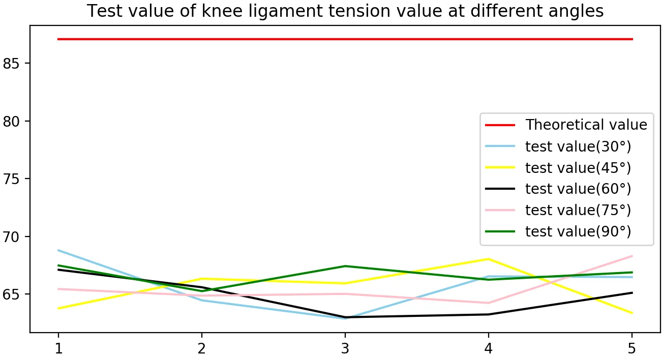
The mechanical analysis of ACL needs to determine the stress-strain relationship. The experimental verification is carried out for the requirements of ACL mechanical analysis. The experimental content includes the test of displacement accuracy and tensile force, and the lateral force model of ACL is verified in different angles in space. The experimental platform shows the UR5 robot-stiffness measuring instrument-ligament fixed platform. During the experiment, the stiffness measuring instrument is mounted on the UR5 arm end effector, and the arm is adjusted so that the tensile direction of the stiffness measuring instrument is stretched to the ligament. The direction is vertical, and stretching at different angles of 30°, 45°, 60°, 75°, and 90° is performed at the same point. The control system and the stiffness measurement experiment are shown in the Fig. 4.
The mechanical properties of the ACL ligament were collected and the mechanical model was used to verify the accuracy of the stiffness tester. The previously prepared pig anterior cruciate ligament material is fixed on the clamping platform, and the UR robot is controlled to make the stiffness measuring instrument and the ligament material form the above different angles, and the measuring instrument is controlled by the upper computer program to stretch the ACL, and the force is obtained. The value and the amount of displacement of the ligament and record the data. As shown in Table 3.
Fig. 4Experimental device: a) Stiffness measurement experiment with UR robot, b) the control system
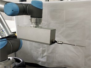
a)
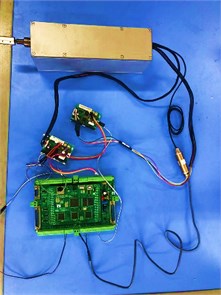
b)
Table 3ACL force test
(30°) | 1 | 2 | 3 | 4 | 5 |
Displacement / mm | 2.3 | 2.3 | 2.3 | 2.3 | 2.3 |
Force measurement / N | 68.774 | 64.442 | 62.854 | 66.521 | 66.461 |
Force theoretical value / N | 87.072 | 87.072 | 87.072 | 87.072 | 87.072 |
/ % | 21.01 | 26.04 | 27.81 | 23.60 | 23.67 |
(45°) | 1 | 2 | 3 | 4 | 5 |
Displacement / mm | 2.3 | 2.3 | 2.3 | 2.3 | 2.3 |
Force measurement / N | 63.751 | 66.317 | 65.917 | 68.026 | 63.358 |
Force theoretical value / N | 87.072 | 87.072 | 87.072 | 87.072 | 87.072 |
/ % | 26.78 | 23.84 | 24.30 | 21.87 | 27.23 |
(60°) | 1 | 2 | 3 | 4 | 5 |
Displacement / mm | 2.3 | 2.3 | 2.3 | 2.3 | 2.3 |
Force measurement / N | 67.093 | 65.577 | 62.978 | 63.219 | 65.094 |
Force theoretical value / N | 87.072 | 87.072 | 87.072 | 87.072 | 87.072 |
/ % | 22.95 | 24.69 | 27.67 | 27.39 | 25.24 |
(75°) | 1 | 2 | 3 | 4 | 5 |
Displacement / mm | 2.3 | 2.3 | 2.3 | 2.3 | 2.3 |
Force measurement / N | 65.424 | 64.851 | 65.006 | 64.218 | 68.276 |
Force theoretical value / N | 87.072 | 87.072 | 87.072 | 87.072 | 87.072 |
/ % | 24.86 | 25.52 | 25.34 | 26.25 | 21.59 |
(90°) | 1 | 2 | 3 | 4 | 5 |
Displacement / mm | 2.3 | 2.3 | 2.3 | 2.3 | 2.3 |
Force measurement / N | 67.465 | 65.241 | 67.413 | 66.235 | 66.867 |
Force theoretical value / N | 87.072 | 87.072 | 87.072 | 87.072 | 87.072 |
/ % | 22.52 | 25.07 | 22.58 | 23.93 | 23.20 |
Table 4Experimental parameters
/ N | / mm | / mm2 | / MPA | / mm |
50 | 15.18 | 29.642 | 78.767 | 2.3 |
6. Conclusions
The experimental parameters are shown in Table 4. After obtaining the experimental materials, the parameters of the experimental materials were obtained according to the referenced mathematical model: the ligament pre-tightening force was 50 N, the initial length of the ligament was 15.18 mm, the cross-sectional area was 29.642 mm2, and the elastic modulus was 78.767 MPa. From the experimental data results of Table 3. The error between the actual tensile force and the theoretical tensile force of the mechanical model ranges from 20 % to 28 %, and the error difference at different angles is small, indicating that the stiffness measuring instrument can measure the tensile force value of the ligament at different angles, and prove that it can be spatially The use also proves the availability of the stiffness measuring instrument.
A 2-DOF stiffness measuring instrument was developed to assist doctors in the evaluation of ACL reconstruction surgery in the absence of timely and effective evaluation of the anterior cruciate ligament reconstruction after knee surgery. After analyzing the accuracy and safety strategy of postoperative evaluation of ACL reconstruction, the function, mechanism and control system of the stiffness measuring instrument are described. Finally, the feasibility of various functions of the system is verified by experiments. It is proved that the stiffness measuring instrument can realize the functional requirements of the design.
This set of stiffness measuring instruments is used in combination with UR robots and laboratory platforms to provide multi-dimensional measurement functions. A limitation that is different from the measurement of the ligament plane is proposed, and the measurement means that can be used flexibly in space can be verified, and the accuracy of the measuring instrument for evaluating the stiffness measuring instrument at different angles in space can be verified. The force measuring instrument system has the advantages of small hardware, modularity, low power consumption, high reliability, high rigidity, etc., and the modular structure of the software system makes the system have good openness, readability, scalability and maintainability.
Stiffness measuring instruments provide postoperative evaluation of ACL surgery is a new development direction of medical robots [7, 8]. It provides a scientific and accurate assessment system to assist doctors in the rehabilitation of ACL reconstruction. It provides a good postoperative evaluation method for ACL reconstruction surgery, ACL stiffness. The measuring instrument system is bound to have a good application prospect in medical field.
References
-
Frisbie D. D., Oxford J. T., Southwood L., et al. Early events in cartilage repair after subchondral bone microfracture. Clinical Orthopaedics and Related Research (1976-2007), Vol. 407, 2003, p. 215-227.
-
Hu Y., Wang T., Yang C., et al. Force-measuring robot for evaluation of ACL reconstruction. Robot, Vol. 31, Issue 6, 2009, p. 605-606.
-
Arnold M. P., Blankevoort L., Ham A. Ten, Verdonschot N., et al. Twist and its effect on ACL graft forces. Journal of Orthopaedic Research, Vol. 22, Issue 5, 2004, p. 963-969.
-
Kaplan Michael J., Howe James G., Fleming Braden, et al. Anterior cruciate ligament reconstruction using quadriceps patellar tendon graft. The American Journal of Sports Medicine, Vol. 19, Issue 5, 1991, p. 458-462.
-
Cui Ze, Chen Zhenghao, Qian Donghai, Ni Gaofeng, et al. Research on Biomechanical Properties of Anterior Cruciate Ligament in the Reconstruction. IEEE International Conference on Robotics and Biomimetics (ROBIO), 2018, p. 206-1255.
-
Panni Alfredo Schiavone, Milano Giuseppe, Tartarone Mario, et al. Clinical and radiographic results of ACL reconstruction: A 5- to 7-year follow-up study of outside-in versus inside-out reconstruction techniques. Knee Surgery, Sports Traumatology, Arthroscopy, Vol. 9, Issue 2, 2001, p. 77-85.
-
Shoham M., Burman M., Joskowicz L., et al. Bone-mounted miniature robot for surgical procedures: Concept and clinical applications. IEEE Transactions on Robotics and Automation, Vol. 19, Issue 5, 2003, p. 893-901.
-
Kneissler M., Hein A., Matzig M., et al. Concept and clinical evaluation of navigated control in spine surgery. IEEE Advanced Intelligent Mechatronics, 2003, p. 1084-1089.
About this article

