Abstract
A dynamical model is proposed in this paper to study the synchronization and stability of the secondary isolation system with a dual-motor excitation. After deducing the dynamic equations of the system by Lagrange’s equation, the Laplace transform is used to deduce the displacement responses of the system when the system operate in steady state. The synchronous balance equation and stability condition of the system is derived with average method, and the relationship between the coefficient of synchronous ability and the geometric parameters of the system is discussed. It can be found that synchronization ability of the system is gradually increased with the increase between two motors mounting distance; meanwhile the larger difference of the mass between the two unbalanced rotors, the more difficult to implement synchronous operation of the system. Moreover, the stable phase difference of the vibrating system being as the key determinant to reach synchronization is discussed numerically. The research result shows that the synchronous behavior of the system is influenced by rotation direction of the rotors, mounting position of two motors, and mass ratios between unbalanced rotors and vibrating body. The correctness of theoretical analyses is verified by simulation results with Runge-Kutta method.
Highlights
- In order to guarantee the synchronous operation between the two rotors, the synchronous torques of the system must be greater than or identical with the absolute value of the difference of residual.
- The phase difference α located in region of (-π/2-θc, π/2-θc) is stable phase difference.
- The drilling shaker of the secondary isolation system can implement synchronous operation and has good isolation effect.
1. Introduction
Synchronization phenomena exists in many aspects of life, such as synchronization in uncoupled neuron system [1], gears [2] and coupled self-sustained electromechanical devices [3]. The phenomenon of synchronization was first discovered by a Dutch physicist Huygens by observing two swinging clocks. After that, Signul, Swedish inventor, has applied for the patent of simplest self-synchronous vibrating machine in 1950 [4]. In 1960s, professor Blekhman of the Soviet Union studied the stability of two synchronously operating exciters by the Poincare-Lyapunov method, and gave the definition of synchronization from the point of view of kinematics and dynamics [5]. On this basis, professor Wen et al proposed the method of small parameter modified average, and solved the synchronization and stability of multiple rotors system [6-8]. Sperling presented a two-plane automatic balancing device for equilibration of rigid-rotor unbalance, and it not only derives dynamic equations for the considered system, but also gives to the discussion of numerical computation findings as well as determines of the synchronous stability conditions according to an analytical approximation [9]. Besides, Balthazar gave some comments on synchronization in pre-resonance and resonance region between DC motors coupling with a flexible strut structure by numerical simulations, and “Sommerfeld effect” of self-synchronization of the system was also analyzed by numerical simulations [10]. Li studied double synchronous states of two motors with horizontal asymmetric structure, and found that the synchronous state can be obtained easily when the system operate in super-resonant state [11]. Synchronization condition and synchronous stability of an elastically coupled rotors in vibration systems are considered by Fang and Hou et al, it is indicated that the synchronous characteristics between rotors are also influenced by stiffness coefficient of coupling springs [12, 13]. Based on active control strategy, Kong implemented ideal synchronization control between the three rotors by employing an adaptive sliding mode algorithm [14, 15]. The above scholars discussed the synchronization theory and synchronization control theory of rotors in vibration system, but theoretical research on the synchronization of rotors in vibrating isolation system is less reported.
At present, with the wide application of vibrating machines, the adverse impacts in their operation process are also gradually appeared. Especially in the synchronous operation for large vibrating screens of offshore drilling platform, some vibration forces produced by the unbalanced rotors operating are transmitted to supported platforms, which can directly lead to platform vibration and generate noise. Meanwhile, some serious accidents are caused such as bolt looseness, fatigue failure of the supported platform and even hazardous for mankind's physical and mental health. In this context, Li proposed a vibrating machine with a two-stage vibration isolation frame and discussed its self-synchronization theory, which found that self-synchronous motion is also achieved when the parameters of vibration system simultaneously satisfy the condition of self-synchronous motion and the stability condition [16]. Anti-resonance machines of a new vibration machinery are proposed by Liu, as well as synchronization and synchronous transmission are studied on considering speed of motors, spring coefficients and geometric parameters of the system [17, 18]. Besides, Liu concerned self-synchronous motion of a dual-mass with two motors vibrating system, and analyzed quantitatively speed of two motors, phase difference between two motors and motion of the system in vibrating direction [19]. Therefore, in present work, taking dynamical model of the secondary isolation system with a dual-motor excitation for example, the synchronous stability will be discussed by the Poincare method, which provide theoretical guidance for designing new types of vibrating isolation machines.
The synchronous characteristics of the secondary isolation system with a dual-motor excitation is discussed in the following sections. The simplified model is described by mathematical formula in Section 2. The stable approximation solutions of vibrating system are obtained by the Laplace transformation method in Section 3. The synchronization equation and stable condition of the vibrating system are obtained through Poincare-Lyapunov method in Section 4. The stable phase difference is numerically analysis through the theoretical results in Section 5. The results of theoretical analysis are verified through computer simulation in Section 6. Finally, the conclusions are summarized in Section 7.
2. Simplified model description
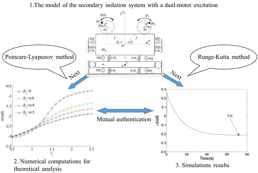
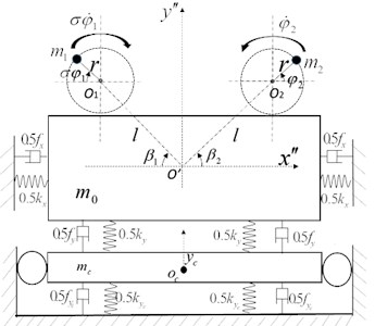
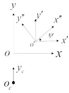
Fig. 1 shows the dynamic model with a dual-motor excitation in the secondary isolation system. The system consists of a rigid vibrating body, a isolation body, springs, unbalanced rotors and motors. The two induction motors are directly fixed installed in vibrating body, which is connected with the isolation body in the vertical direction and foundation in the horizontal direction by the springs () [N/m]. The isolation body is directly connected to the foundation by two springs () [N/m]. Two unbalanced rotors actuated by the motors produce the excitation forces to stimulate the motion of the whole system. And the distance between the pivot of two motors and the centroid of the vibrating body is [m]. [rad] represents the installed angle of motor 1 between and , and [rad] represents the installed angle of motor 2 between and . Eccentric distance of the unbalanced rotors is denoted by [m]. The damping coefficients of the springs are , , and [N·s/m], respectively. , and are displacement responses of centroid of the vibration body in -, - and - direction, respectively. is displacement response of isolation body in - direction. and are the initial phase of rotor 1 and 2, respectively. represents the rotation direction of the rotors. The two rotors rotate in the same direction when –1, and the two rotors rotate in the opposite direction when 1.
In reference frame , the center coordinates and of the two unbalanced rotors can be separately expressed as:
Fig. 1The model of the secondary isolation system with a dual-motor excitation: a) dynamic model, b) the reference frame of system
a)
b)
In the reference frame , the center coordinates ( 1, 2) of two rotors can be separately written as:
In this case. The kinetic energy of the vibration system can be obtained by:
where, is rotational inertia of the vibration body, [Kg∙m2]; and are rotational inertia of the two rotors, [Kg∙m2].
The potential energy of the vibration system can be described as:
The dissipation energy of the whole system can be given by:
Finally, dynamic equations of the system can be deduced by Lagrange equation:
where, in the vibration system, the generalized force matrix can be assumed as:
where, and are the electromagnetic torque of induction motors. and are the friction and damping torque of the rotors.
Substituting Eqs. (4), (5), (6) and (8) into Eq. (7), considering , , the dynamic equations of the system can be obtained as follows:
where, , , , .
3. Stable approximation solutions of the system
In the light of Eq. (9), the vibration equations are coupled in the direction of and . In steady state of the system, the displacements of the system are weakly influenced by the angular acceleration of the rotors, therefore, acceleration and closed to zero can be ignored. In the process, the following parameters are introduced as follows:
Submitting Eq. (10) into the first four equations of Eq. (9), the following equations are obtained:
The first two equations in Eq. (11) is no coupling term, which can be directly obtained by solving the second order differential equation. The latter two equations are coupled in directions and , and so the Laplace’s transformation method is employed to solve them under initial conditions , , , . Therefore, the transfer function of relevant formulas can be obtained by
where:
Assuming , Eq. (12) can be simplified as:
where:
In this case, the approximation displacements of the system in steady state can be rewritten as:
where:
In Eqs. (14) and (16), the parameters ( are the coupling coefficient between the rotors, the vibration body and the isolation body, respectively.
The vibration transmission in this paper is described by amplitude ratio in anddirection. According to Eqs. (15) and (16), the amplitude of the system is the product of amplitude amplification factor and sine function. Ignoring weakly damped of the system (i.e. , 1, 2), ability of the vibration transmission can be described by:
where represents ability of the vibration transmission of the system.
4. Synchronization and stability of the system
4.1. Synchronous condition
The synchronous behavior of the secondary isolation system with a dual-motor excitation can be estimated with the Poincare method, and so the phase angle of the rotors can be defined by:
Asumming is phase difference between rotor 1 and 2 i.e.:
According to Eq. (15), the two-order derivative of , and with respect to time can be calculated. Substituting , and into the last two formulas of Eq. (9), and then integrating and averaging this equation related over period , respectively, synchronous indexes and , i.e., average load torque of the motors, can be obtained by:
where, and , 1, 2, which represents the electromagnetic torque and friction torque in the motor shafts, respectively.
Eqs. (20) and (21) can be further rearranged as following:
where:
In Eq. (24), and are defined as sine coefficients of lagging phase (), is defined as cosine coefficients of lagging phase Therefore, the value of and is far smaller than on account of the small value of lagging phase .
Therefore, the possible synchronous operation between the rotors can be determined according to Eqs. (22) and (23), i.e.:
When the two rotors operate in synchronous state, Eq. (25) can be applied to find the approximation of rated speed of the motors. is the sum of the electromagnetic torque of the two induction motors; the term of is the sum of the friction torque of the two rotors; the other items represent the load torque of the two rotors. Therefore, the equation of the vibrating torque between the rotors can be obtained by Eq. (25) when the rotors operate in the steady state. And the value of phase difference can be calculated by Eq. (26). Considering Eq. (26), the synchronous torque and the difference of residual torque can be defined as:
where, , . The is the synchronous torque, also known as the frequency capture torque; the is the difference between the motor 1 and 2 of residual torque. The and are the residual torque in motor 1 and 2, respectively.
Substituting Eqs. (27) and (28) into Eq. (26), the phase difference between the rotors can be determined by:
According to Eq. (29), the phase difference between the rotors is a function related to the parameters , and .
On the account of , the synchronous condition of the system can be expressed by:
In the light of Eq. (30), in order to guarantee the synchronous operation between the two rotors, the synchronous torques of the system must be greater than or identical with the absolute value of the difference of residual torque between the two motors.
The coefficient of synchronous ability of the system can be expressed by:
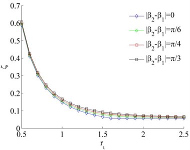
where, is maximum of the load torque of the system, i.e., . The smaller coefficient of synchronous ability, the easy to implement of synchronous operation. When the system synchronization coefficient is greater than 1, it is difficult to realize synchronous motion for the system. In light of Eq. (31), the coefficient of synchronization ability is related to load torque and synchronous torque , that are the function of , , , and with damping ratio (). As shown in Fig. 2, the coefficient of synchronous ability is gradually increased with the increase of the installation angle when the two rotors rotate in reverse direction (i.e., ). And the coefficient of synchronous ability is the first decreased and then stabilized with the increase of , as shown in Fig. 2(a). Therefore, the smaller value of and the larger value of are in favor of reversely synchronous operation of the rotors. When the two rotors operate in the same direction (i.e., –1), the coefficient of synchronous ability is the first increased and then the decreased with the increase of . And the maximum value of the coefficient of synchronous ability is appeared when 1.4, as shown in Fig. 2(b).
Fig. 2Coefficients of the synchronous ability when η1= 0.02 and η2= 0.02
a) 1
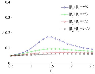
b)–1
Fig. 3Coefficients of the synchronous ability when η1= 0.02
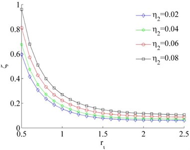
a) 1,
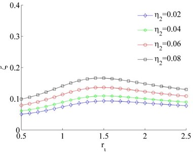
b)–1,
However, the fluctuation of the synchronous coefficient is gradually decreased with the increase of . Therefore, synchronization ability of the system is gradually increased with the increase between two motors mounting distance. From Fig. 3(a, b), the coefficient of synchronous ability of the system is increased with the increase of the mass ratio . In other words, the larger difference of the mass between the two rotors, the more difficult to implement synchronous operation of the system.
4.2. Synchronous stability
According to Bleckman’s method [4], the synchronous stability of system can be determined by synchronization indexes and , as shown in Eq. (32). It can be seen that the real part root of reflects the stability of phase difference between rotors. If the real part of is a negative number, the phase difference exists stability solution. If have a real part with a positive root, the value of phase difference is unstable. And if any one of roots is equal to zero, the central flow theorem can be applied to determine the stability of the synchronization. In light of Eq. (26), the can be obtained as:
Therefore, the condition of the synchronous stability can be expressed as:
Considering Eq. (33), phase difference located in region of () is stable. When the parameters of the system satisfy the synchronization condition and the synchronization stability condition, the synchronous motion of the system can be implemented.
5. Numerical computations for theoretical analysis
The stable synchronization behavior of the system can be obtained by Poincare method. According to Eqs. (29) and (31), the phase difference is determined by parameters , and , that is the function of frequency ratios , damping ratios , mass ratios (), geometrical parameters () and rotation direction of the rotors (). However, when the damping coefficients are very small, the synchronization state of the system is less affected by damping ratio. Meanwhile, the system is a far resonance system, and the value of frequency ratios is greater than or equal to 5. Therefore, mass ratios, the rotating direction and geometrical parameters are the important parameters to influence behavior of the proposed system.
5.1. Synchronous state for 1, , 5
When the mass of the unbalanced rotors is identical and the rotors rotate in the opposite direction (i.e., ), the mass ratios () between the rotors and the vibrating body should be equivalent (i.e. ). In addition, because of the type of two motors is the same, the residual torque difference between two motors should be zero, i.e., . Thus, Eq. (26) can be simplified as . According to Eq. (24), it can be obtained that and . Thus, there are two solutions for in this situation, i.e., or . Considering Eq. (33), the stable solution for can be obtained, i.e., .
5.2. Synchronous state for 1, ,5
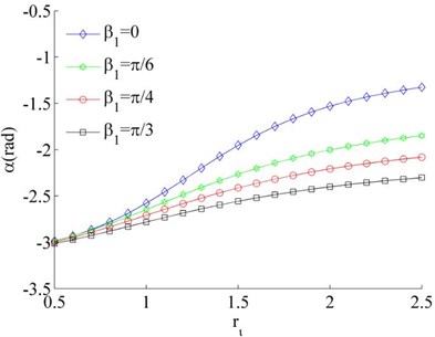
Consider the values of the dimensionless parameters in the system to be , , Because of Eq. (26) can be simplified as . Therefore, stable phase difference α of the system can be obtained by combining with Eq. (31). According to Fig. 4, it is indicated that the value of the stable phase difference is gradually increased with the increase of , and decreased with the increase of . Comparing Fig. 4 (a) and (b), the value of the stable phase difference is weak influenced by the change of mass ratios. Meanwhile, the mounting distance between two motors is not influence on the stable phase difference of the system when two motors rotating in opposite direction.
Fig. 4Stable phase difference when η1≠η2
a), ,
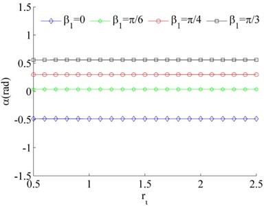
b), ,
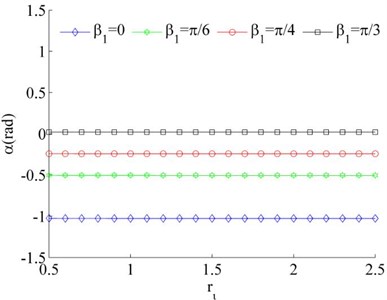
c), ,
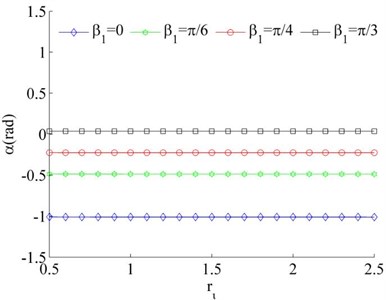
d), 0.02,
5.3. Synchronous state for –1,, 5
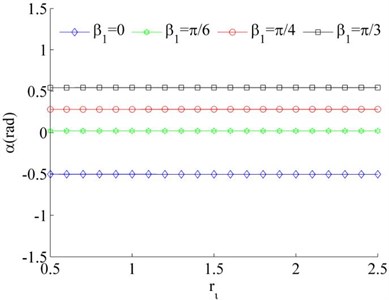
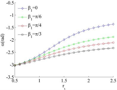
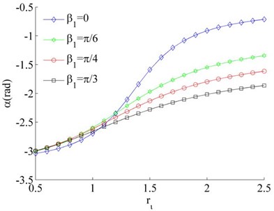
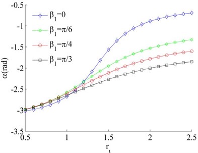
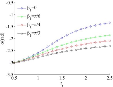
Considering the mass of the unbalanced rotors to be identical, Eq. (26) can be simplified as . And then considering Eq. (24) and Eq. (31), the stable phase difference can be obtained, as shown in Fig. 5. It follows that the stable phase difference is gradually increased with the increase of parameter , and decreased with the increase of the installation angles , . As , thus the synchronous state between the rotors is mainly determined by the installation position of the motors when the rotors operated in the same direction.
5.4. Synchronous state for –1, , 5
Considering the mass of the unbalanced rotors to be different, the mass ratios is different, such as and or 0.04. Thus Eq. (26) can be rewritten as under the condition of . In this case, the stable phase difference is shown in Fig. 6 as two rotors rotate in the same direction. It can be seen that the stable phase difference between the rotors is also influenced by parameters , and . The stable phase difference of the system is weak affected by the mass ratios () of the rotors. And the phase difference between the motors is gradually increased with the increase of parameter . Comparing Fig. 6(a) and (c), the phase difference is gradually decreased with the increase of the installation angles ().
Fig. 5Stable phase difference when η1=η2
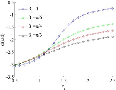
a)
b)
Fig. 6Stable phase difference when η1≠η2
a), 0.02, 0.03
b), 0.02, 0.04
c), 0.02, 0.03
d), 0.02, 0.04
6. Simulations results
To further verify the validity of the theoretical analysis, the dynamic characteristics of the system can be determined by Eq. (9) with employing Runge-Kutta method.
6.1. The dynamic characteristics 1, , 5
The values of corresponding parameters in the simulation model are , , , , , , , , , , , , , 50, 100, 0.05, 0.3, 10. The dynamics characteristics of the system can be obtained by computer simulations, as shown in Fig. 7. As shown in Fig. 7(a), when the motors are supplied with the power source at the same time, the velocities of two motors are consistent in the whole operation stage as uniformity of the rotational inertia of the unbalanced rotors. According to Fig. 7(b), the phase difference between the rotors is stabilized to zero, which is good agreement to theoretical analysis in section 5.1. The displacement responses of the vibrating body in - - and - directions are shown in Fig. 7(c, e, f); the displacement response of the isolation body in - direction is shown in Fig. 7(d). The displacement response in - and - directions are zero due to symmetrical installation of two asynchronous motors. Thus, the vibrating body only oscillates in - direction. Comparing Fig. 7(d) and (e), the amplitude of the isolation body is far smaller than the amplitude of the vibration body, so the measure of vibration isolation in the system is effective.
Fig. 7The dynamic characteristics of the system when η1=η2, σ= 1

a) Velocity of the motors
b) Phase difference between the rotors
c) Displacement response in direction
d) Displacement response in direction
e) Displacement response in direction
f) Displacement response in direction
6.2. The dynamic characteristics for 1, 0.02, 0.03, 5
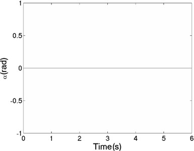
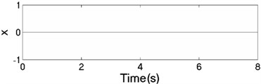
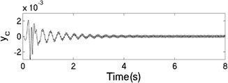
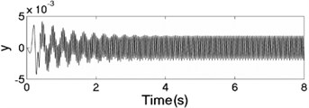
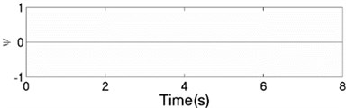
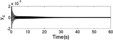
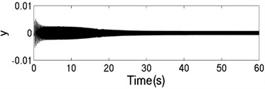
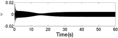
The unbalanced rotors with the different mass are reversely driven by two motors. The values of the parameters in simulation model are assumed in follows: , , , , , , , , 1, , , 2, 3, 50, 100, 0.05, 0.3, 10. The dynamic characteristics of the system can be obtained by computer simulations, as shown in Fig. 8. In the light of Fig. 8(a), the velocities of motors are different in initial stage as inconsistency of the rotational inertia of the unbalanced rotors, but it will be gradually stabilized at 157 [rad/s]. According to Fig. 8(b), it can be seen that the phase difference between the rotors is equal to –0.22 [rad], which is good agreement to the theoretical analysis in Fig. 4(c). In this case, the displacement responses of the vibrating body in - - and - directions are shown in Fig. 8(c, e, f); the displacement response of the isolation body in - direction is shown in Fig. 8(d). Therefore, the vibrating body is oscillated in plane. And the vibration body is rotated around the x axis due to a moment of force produced by two unbalanced rotors, as shown in Fig. 8(f). Compared Fig. 8(d) with Fig. 8(e), the amplitude of the isolation body is also far smaller than the amplitude of the vibration body in vertical direction, so the measure of vibration isolation in the system is effective.
Fig. 8The dynamic characteristics of the system when η1≠η2, σ= 1
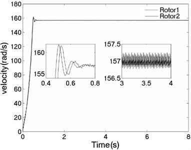
a) Velocity of the motors
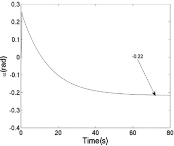
b) Phase difference between the rotors
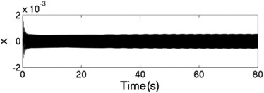
c) Displacement response in direction
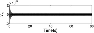
d) Displacement response in direction
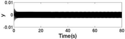
e) Displacement response in direction
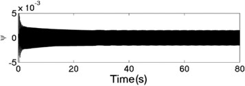
f) Displacement response in direction
6.3. The dynamic characteristics for –1, , 5
The values of corresponding parameters in the simulation model are , , , , , , , , –1, , , 2, 2, 50, 100, 0.05, 0.3, 10. The dynamics characteristics of the system can be obtained by computer simulations, as shown in Fig. 9. The velocities of the two motors are consistent in Fig. 9(a) due to the same value of the rotational inertia of two unbalanced rotors. The phase difference between the rotors is stabilized at –2.66 [rad] in synchronous state, as seen in Fig. 9(b), which is consistent with the theoretical analysis in Fig. 5(a) as well. The displacement responses of the vibrating body in - - and - directions are shown in Fig. 9(c, e, f); the displacement response of the isolation body in - direction is shown in Fig. 9(d). It can be seen from the simulation results, the vibrating body driven by the motors is oscillated in the plane, and the vibration body is rotated around the axis due to due to a moment of force produced by two unbalanced rotors. Compared Fig. 9(d) with Fig. 9(e), the amplitude of the isolation body is also far smaller than the amplitude of the vibration body in vertical direction, so the measure of vibration isolation in the system is effective.
Fig. 9The dynamic characteristics of the system when η1=η2, σ= –1
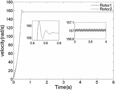
a) Velocity of the motors
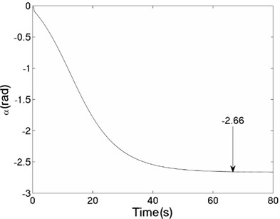
b) Phase difference between the rotors
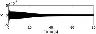
c) Displacement response in direction
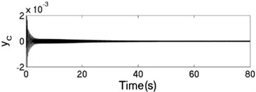
d) Displacement response in direction

e) Displacement response in direction
f) Displacement response in direction
6.4. The dynamic characteristics for –1, 0.02, 0.03, 5
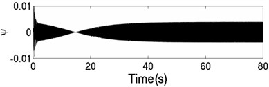
The unbalanced rotors with the different mass are respectively driven by two motors, rotating in the same direction. At this time, the values of the parameters in simulation model are assumed in follows: , , , , , , , 44, –1, , , , , 50, 100, 0.05, 0.3, 10. The dynamics characteristics of the system can be obtained by computer simulations, as shown in Fig. 10. In th light of Fig. 10(a), the velocities of two motors are different in the started stage, but gradually stabilized at 157 [rad/s]. As shown in Fig. 10 (b), the phase difference between two rotors is stabilized to –2.68 [rad], which is fitted well to the theoretical analysis in Fig. 6(a). In this case, the displacement responses of the vibrating body in - - and - directions are shown in Fig. 10(c, e, f); the displacement response of the isolation body in - direction is shown in Fig. 10(d). Thus, the vibrating body driven by the motors is oscillating in the plane. Compared Fig. 10(d) with Fig. 10(e), the amplitude of the isolation body is less than the amplitude of the vibration body in vertical direction, which is indicated that vibration displacement transmitting the foundation is weakened by adding a isolation body, thus the vibration isolation function of the system is reliable.
Fig. 10The dynamic characteristics of the system when η1≠η2, σ= –1
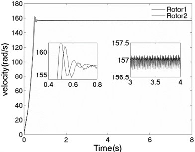
a) Velocity of the motors
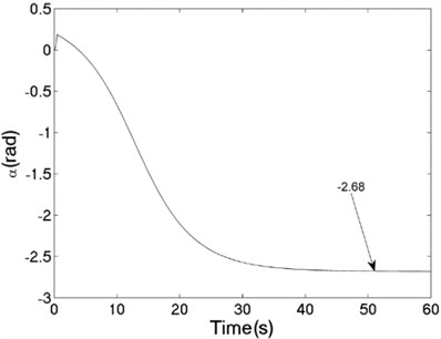
b) Phase difference between the rotors
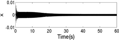
c) Displacement response in direction
d) Displacement response in direction
e) Displacement response in direction
f) Displacement response in direction
7. Conclusions
In this paper, a dynamical model of the secondary isolation system with a dual-motor excitation is proposed to discuses the synchronization and stability by Poincare method. According to the theoretical derivation and numerical analysis, some conclusions are stressed as the following:
1) To guarantee the synchronous operation between the two rotors, the synchronous torques of the system must be greater than or identical with the absolute value of the difference of residual torque between the two motors.
2) Synchronization ability of the system is gradually increased with the increase between two motors mounting distance; meanwhile the larger difference of the mass between the two unbalanced rotors, the more difficult to implement synchronous operation of the system.
3) When phase difference between two rotors is in region of (), stable condition of the system is realized.
4) The phase difference between the rotors is influenced by rotation direction (), installation angle (), the mounting distance between two motors () and mass ratios (). When the two rotors are rotated in the opposite direction (i.e., 1), the stable phase difference is only determined by installation angles (, ) of the motors, and the value of phase difference α is equal to installation angle difference (). When the two rotors are rotated in the same direction (i.e., –1), the value of phase difference α is related to installation angles (, ) and the mounting distance between two motors () of the motors.
The value of the stable phase difference is gradually increased with the increase of the mounting distance between two motors (), and decreased with the increase of installation angles (). The stable phase difference is weak affected by the mass ratios () when the mass difference between the rotors remains small. However, when the mass difference between the rotors is too great, the system is difficult to realize synchronous operation.
5) According to simulations results, vibration displacement transmitting the foundation is weakened by adding an isolation body, thus the vibration isolation function of the system is reliable.
References
-
Zhang J., Huang S., Pang S. Synchronization in the uncoupled neuron system. Chinese Physics Letters, Vol. 32, 2015, p. 13-17.
-
Junichi H., Daisuke I., Ichiro M., Takao K. Proposal of encoder-less time synchronous averaging method utilizing nonlinear oscillator for gears in operation. Journal of Advanced Mechanical Design, Systems, and Manufacturing, Vol. 12, 2018, p. 1-11.
-
Yamapi R., Woafo P. Dynamics and synchronization of coupled self-sustained electromechanical devices. Journal of Sound and Vibration, Vol. 285, 2015, p. 1151-1170.
-
Blekhman I. I. Synchronization in Science and Technology. ASME Press, New York, 1988.
-
Blekhman I. I., Landa P., Rosenblum M. Synchronization and chaotization in interacting dynamical systems. Applied Mechanics Reviews, Vol. 48, 1995, p. 733-733.
-
Zhao C. Y., Wen B. C., Zhang X. L. Synchronization of the four identical unbalanced rotors in a vibrating system of plane motion. Science China Technological Sciences, Vol. 53, 2010, p. 405-422.
-
Zhang X. L., Wen B. C., Zhao C. Y. Vibratory synchronization and coupling dynamic characteristics of multiple unbalanced rotors on a mass-spring rigid base. International Journal of Non-Linear Mechanics, Vol. 60, 2014, p. 1-8.
-
Zhang X. L., Wen B. C., Zhao C. Y. Vibratory synchronization transmission of a cylindrical roller in a vibrating mechanical system excited by two exciters. Mechanical Systems and Signal Processing, Vol. 96, 2017, p. 88-103.
-
Sperling L., Ryzhik B., Linz C., Duckstein H. Simulation of two-plane automatic balancing of a rigid rotor. 2nd International Conference on Control of Oscillations and Chaos (COC-2000), Vol. 58, 2002, p. 351-365.
-
Balthazar J., Felix J., Brasil R. Short comments on self-synchronization of two non-ideal sources supported by a flexible portal frame structure. Journal of Vibration and Control, Vol. 10, 2004, p. 1739-1748.
-
Lingxuan L., Xiaozhe C. Double synchronization states of two exciters with horizotal asymmetric structure in a vibrating system. Journal of Vibroengineering, Vol. 19, 2017, p. 3883-3894.
-
Hou Y., Fang P. Synchronization and stability of two unbalanced rotors with fast antirotation considering energy balance. Mathematical Problems in Engineering, Vol. 2015, 2015, p. 1-15.
-
Fang P., Hou Y. Synchronization characteristics of a rotor-pendula system in multiple coupling resonant systems. Proceedings of the Institution of Mechanical Engineers, Part C: Journal of Mechanical Engineering Science, Vol. 232, 2018, p. 1802-1822.
-
Kong X. X., Zhang X. L., Chen X. Z., Wen B. C., Wang B. Synchronization analysis and control of three eccentric rotors in a vibrating system using adaptive sliding mode control algorithm. Mechanical Systems and Signal Processing, Vol. 72, 2016, p. 422-450.
-
Kong X., Chen C., Wen B. Composite synchronization of three eccentric rotors driven by induction motors in a vibrating system. Mechanical Systems and Signal Processing, Vol. 102, 2018, p. 158-79.
-
Li H., Liu D., Jiang L., Zhao C. Y., Wen B. C. Self-synchronization theory of a vibrating system with a two-stage vibration isolation frame driven by two motors. Journal of Vibration and Shock, Vol. 33, 2014, p. 134-140.
-
Liu J., Jiao C., Li X., Li Y., Liu J. Dynamic parameters selection method and simulation of the anti-resonance vibration machine. The 2nd International Conference on Computer and Automation Engineering (ICCAE), Vol. 4, 2010, p. 457-462.
-
Liu J., Liu J., Sun C., Zhang C. Y. Vibration synchronization and vibratory synchronization tranismission of anti-resonance vibrating machines. Journal of Mechanical Engineering, 2015, p. 95-103.
-
Liu Y., Zhang X. L., Wen B. C. Self-synchronous motion of a dual-mass with two motors vibrating system. Chinese Journal of Construction Machinery, Vol. 15, 2017.
Cited by
About this article

This study is supported by supported by National Natural Science Foundation of China (Grant No. 51705437), Open Fund (OGE201702-18) of Key Laboratory of Oil and Gas Equipment, Ministry of Education (Southwest Petroleum University), scientific research starting project of SWPU (No. 2017QHZ009) and Sichuan Science and Technology Program (2018RZ0101).
