Abstract
In this paper, through analyzing Tc bearing by the theory of Hydrodynamic lubrication, the unsteady Reynolds equation of Tc bearing under the dynamic-state condition is initially established. The formula of Tc bearing’s liquid-film dimensionless stiffness coefficient and damping coefficient is derived. Furthermore, two kinds of the distribution curves of Tc bearing’s liquid-film dimensionless stiffness coefficient, damping coefficient against Tc bearing’s eccentricity ratio and width-diameter ratio are displayed respectively, and the stability criterion of liquid film is worked out and the angular speed of instability of bearing shaft is calculated. Overall, conclusions are drawn: downhole system improves the entire system’s stability by enhancing the stiffness of bearing shaft itself. The improvement of the stability of bearing shaft itself, which can be done by altering the structure of Tc bearing and adopting better spiral flutes and ellipse groove can strengthen the whole system’s stability. The high width-diameter ratio of Tc bearing increases the liquid film’s stiffness coefficient and damping coefficient of Tc bearing. The rotational rate of rotary table is lower than half of that of the supporting system of Tc bearing.
1. Introduction
With the advantages of small radial size, great bearing capacity, good impact resistance and good vibration resistance, etc., downhole tools with rotary dynamic seal mode, such as the continuous wave pulse generator, may have their rotary dynamic seal mode replaced by magnetic coupling to construct Tc bearing in order for longer service life.
When working normally, Tc bearing require being cooled and lubricated by drilling fluid. Speaking of its working principle, it is a special dynamic lubricated bearing. What’s special to Tc bearing is that there is no need to take lubrication flow and temperature rising into account, when soaking in the drilling fluid, of which the flow rate is up to 20-30 m/s, with particles whose granularity is 74 µm. In order to prevent the flush effects of drilling fluid as well as the tear and wear of particles, tungsten carbide alloy powder [1] and blocks of high hardness are sintered on the surface of bearing’s steel body to form tough contacting surface.
2. The hydrodynamic model of Tc bearing under dynamic state
2.1. The coordinate system under dynamic pressure and dynamic characteristics of Tc bearing
Reynolds equation is the equation about the dynamic pressure of the liquid film in the inner and outer ring clearance of the bearing, and is the foundation of the hydrodynamic sliding bearing. Its unsteady cylindrical coordinates are as follows [2-4]:
In the formula, is the pressure of the liquid film, whose unit is N/m2; is the lubricant viscosity, whose unit is Pa·s. , whose unit is m, is the thickness of the liquid film, and. is the bearing clearance, and, of which d(r), D(R) are the shaft and bearing straight (half) diameters. is the eccentricity rate, and .The time derivative of the eccentricity e represents the moving speed of the shaft journal center displacement velocity in the direction of the connecting line between the two centers, . represents the swirl velocity of the shaft journal center instantaneous position, , around the static equilibrium point, , as is shown in Fig. 1 on the right.
Fig. 1The coordinate system of hydrodynamic equation and dynamic force diagram of Tc bearing
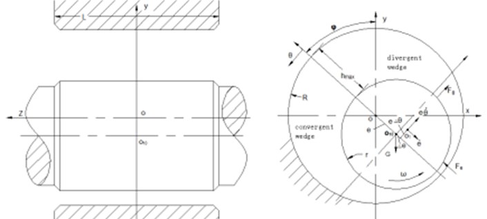
In order to highlight the role of the relevant factors, so that the problem is compact, the variable is often converted to a dimensionless form. Each variable dimensionless transformation formula is , , , is the bearing clearance ratio.
For incompressible drilling fluid, the dimensionless Reynolds equation is:
In this equation, and .
2.2. Dynamic pressure model of Tc bearing
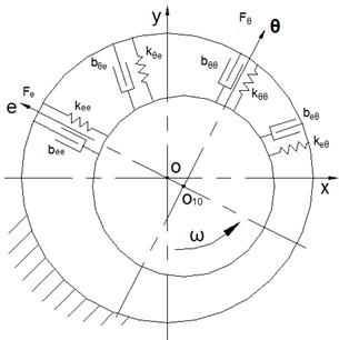
In dynamic analysis, the dynamic pressure bearing is modeled as an elastic damping bearing with 4 stiffness coefficients and 4 damping coefficients, as is shown in Fig. 2.
Fig. 2Mechanical model of Tc bearing
2.2.1. Tc bearing’s liquid-film dimensionless stiffness coefficient and damping coefficient
is used to represent Tc bearing’s liquid-film dimensionless stiffness coefficient. describes Tc bearing’s liquid-film damping coefficient. The non-dimensional stiffness coefficients and damping coefficients are calculated as follows [4-5:
In the formula, there are four liquid-film dimensionless disturbance pressure marked ,,, , which are the partial derivatives of the dimensionless pressure, , on the non-dimensional perturbations , , and . and are the initial angle and the end angle of the liquid film of convergence wedge in the positive pressure region.
2.3. The effects of both eccentric ratio and width-diameter ratio on liquid-film dynamic characteristics
In addition to the initial angle and the end angle of the liquid film of convergence wedge in the positive pressure region, liquid-film dynamic characteristics can be characterized by eccentric ratio and width-diameter ratio, two significant parameters. It is analyzed that the effects of those two parameters on the eight dynamic characteristic coefficients of both non-dimensional stiffness coefficient and damping coefficient of Tc bearing as follows.
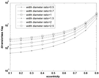
2.3.1. The effects on dimensionless stiffness coefficient
Conclusions can be drawn from the former distribution curves of the non-dimensional stiffness coefficients: Firstly, with the increase of eccentric ratio and width-diameter ratio, four absolute values of liquid-film dimensionless stiffness coefficients are growing. Secondly, when eccentric ratio = 0.7, four absolute values of stiffness coefficients are going up steadily with the increase of width-diameter ratio.
Fig. 3Kee distribution curve
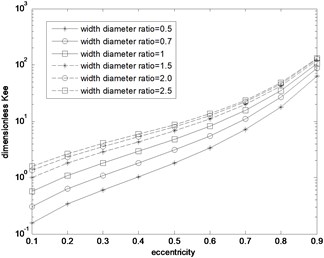
Fig. 4Kφφ distribution curve
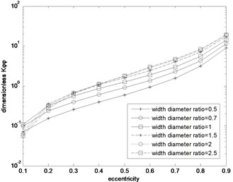
Fig. 5Kφe absolute value distribution curve
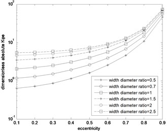
Fig. 6Keφ distribution curve
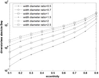
2.3.2. The effects on dimensionless damping coefficients
Conclusions can be drawn from the former distribution curves of the non-dimensional damping coefficients: Firstly, with the increase of eccentric ratio and width-diameter ratio, four absolute values of liquid-film dimensionless damping coefficients are growing. Secondly, when eccentric ratio = 0.7, four absolute values of damping coefficients are going up steadily with the increase of width-diameter ratio.
Fig. 7Bee distribution curve
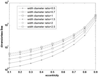
Fig. 8Bφφ distribution curve
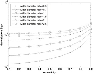
Fig. 9Beφ Absolute value distribution curve

Fig. 10Bφe Absolute value distribution curve
2.4. Stability criterion of liquid film
Speaking from liquid film aspect, the advantages and disadvantages of its stability can be measured by two dimensional parameters, which are , the non-dimensional integrated stiffness of Tc bearing, and , the square of whirl ratio of the shaft journal. indicates the relative value of the non-dimensional integrated stiffness of Tc bearing, while suggest the relative proportional relation between liquid-film eddy coefficient and liquid-film damping coefficient. Therefore, and are two stability indexes for common used radical bearing, and the stability of Tc bearing is better when the value of is higher and is smaller.
the non-dimensional integrated stiffness of Tc bearing is:
The square of whirl ratio of the shaft journal is:
Of which:
The integrated stiffness of liquid film must be great than 0, and 0 is the necessary condition for system stability. If 0, it indicts that liquid-film whirl is unlikely to happen. Thus, 0 is the sufficient condition for system stability. In addition, 0 and 0, which are liquid-film parameters, are the prerequisite conditions for the supporting system stability of bearing shaft axis.
2.5. Instability speed of the supporting shaft system of Tc bearing
In the downhole tool, the Tc bearing, and the supporting shaft system can be regarded as a single mass rotor system. Whether the whole system is stable or not depends on two required conditions: 0 and 0 which are met by the liquid-film dynamic characteristics of Tc bearing, as well as the rotational speed of the shaft. The calculation formulas [21, 23-24] for rotating shaft speed,, when the liquid film appears vortex motion in single rotor system, are as follows.
1) Rate of Unsteady Angular Velocity of Single Mass Rigid Rotor in Single-Span Rotor System is:
2) Unstable Angular Velocity of Single Mass Elastic Rotor in Single-Span Rotor System is:
In these equations, is the first order critical angular velocity of the shaft, and is the stiffness factor of the shaft, whose unit is N/m. is the mass of the shaft, whose unit is kg. In addition, the other parameters are the same as above.
The working angular velocity of the rotating shaft supported by Tc bearing should be lower or higher than that of the unstable angular velocity, otherwise it will trigger liquid-film instability or liquid-film oscillation of Tc bearing.
3. Conclusions
The dynamic instability generated by the shaft system supported by Tc bearing is not only related to the structural parameters of Tc bearing, but to the system parameters.
Therefore, from the physical sense, as to the liquid film of Tc bearing, the greater stiffness and damping, the less probable to be unstable. The experiment also demonstrates that when the eccentric ratio of the shaft journal bearing center is more than 0.7, the instability is less likely to happen. In terms of Tc bearing, however, its eccentric ratio is less than 0.6 as the granularity of drilling fluid is up to 74 µm. Under this condition, three methods can be employed to improve the system stability.
Firstly, improving , the stiffness parameter of the shaft itself, to develop , the critical speed of the system, can strengthen the stability of the whole system. Secondly, changing the structure of Tc bearing and adopting spiral flutes and ellipse groove in order to enhance the stability of bearing itself can solidify the whole system’s stability. Thirdly, increasing the width-ratio of Tc bearing to improve the liquid-film stiffness coefficient and damping coefficient, which makes the bearing itself more stable, can develop the whole system’s stability.
In addition, when operating compound drilling, the rotational rate of rotary table on the ground should be lower than half of that of the supporting system of Tc bearing. The reason is that half-frequency whirl vibration exists in the liquid film of Tc bearing when the shaft is rotating at a certain speed. The half-frequency whirl is the whirl of shaft journal bearing center rotate around its balance point at the rate of greater than or equal to half of the speed of shaft’s rotational rate, aiming to prevent the vibration of the liquid film.
References
-
Xu Fudong, Zhang Xiaodong, Sun Huapeng Theoretical research of contact problem in TC bearing in down hole motor. Oil Field Equipment, Vol. 33, Issue 6, 2004, p. 21-24.
-
Zhou Guiru, Ma Ji, Jin Yongxin Theory of Hydrodynamic Lubrication. Zhejiang University Press, Huangzhou, 1990.
-
Chen Boxian, Qiu Zugan, Zhang Huisheng Theory and Application of Lubrication. China Machine Press, Beijing, 1991.
-
Zhang Zhiming, Zhang Yanyang, Xie Youbai, et al. Hydrodynamic Lubrication Theory of Sliding Bearing. Higher Education Press, Beijing, 1986.
-
Guo Hong, Cen Shaoqi, Zhang Shaolin Design of Cylindrical and Conical Hydrodynamic-Hydrostatic Bearings. Zhengzhou University Press, Zhengzhou, 2014.
About this article

The paper was supported by the special subject “Directional Rotary Geological Guidance System Development” of China National Petroleum Corporation Major Project (2013E-3801).
