Abstract
Introducing friction damping devices in blade structures is an effective measure to reduce the failure rate of aero-engine. The component motion perpendicular to contact surface leads the normal load to vary during vibration, and phase difference of adjacent blades makes the variation non-linear. This article analyzed the influence of non-linearly variable normal load on damper’s vibration-reducing effect, and deduced the formula of hysteresis curve. Using the model raised, this article calculated the vibratory response of a shrouded blade structure and compared the result with experimental data. The conclusion is that macroslip model under the condition of non-linearly variable normal load is accurate and effective in terms of predicting the vibratory response of shrouded blade structure.
1. Introduction
A large amount of damage in gas-turbine structures can be attributed to the high cycle fatigue caused by high stress during vibrating. Reducing the vibratory stress has always been an important topic of blade structure design. It is an effective way to incorporate friction damping facilities into the blade structure during design phase, which normally includes under platform dampers and shrouds.
Macroslip model is widely adopted by researchers when studying vibration reduction problems. Griffin [1] came up with the macroslip model back in 1980, where he treated the damper as series connection of a spring and a coulomb friction pair. Since then, a large number of researchers have did further research with regard of almost every aspect of macroslip model. Sinha [2] studied the effects bought by the difference between maximum static friction force and sliding friction force. Griffin [3] studied mistuned blade-disk structure analyzing the influence of mistuning on damper’s vibration reduction function. Chen [4] came up with the 3D contact model to simulate the three dimensional motion of contact point.
During the vibration of turbine blade with shrouds, the direction of blade vibration is not parallel to the contact surface, which leads to the variation of normal load on the contact surface. Meanwhile, because of the phase difference between adjacent blades the change of normal load on the contact surface is normally non-linearly. This article firstly induces how the normal load change during vibration, and then come up with the hysteresis curves describing the change of friction force on contact surface along with the displacement of contact point. Thus, the macroslip model under the condition of non-linearly variable normal load is came forward. Using this very model this article analyzes the vibratory response characteristics of a shrouded blade and compares the simulation results with the experimental data.
2. Macroslip model
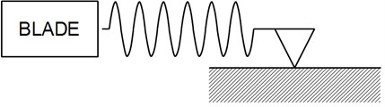
Macroslip model is illustrated in Fig. 1 friction damper is simplified as the series connection of a spring and a coulomb friction pair. During vibration, the blade pulls or pushes the spring, but the contact point won’t slip until the force of spring surpasses the maximum statistic friction force.
Fig. 1Macroslip model
3. Non-linearly variable normal load
In shrouded blade structure, the vibration direction of blade is not parallel to shroud’s surface, which means the normal load on contact surface is changing during the process of vibration, as can be seen in Fig. 2.
Fig. 2Vibration direction of shroud
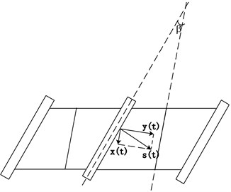
Suppose the displacement of blade vibration is , which could be decomposed as horizontal component which is parallel to contact surface and vertical component which is perpendicular to contact surface.
Under harmonic excitation, . Suppose is the phase difference between the motion parallel to contact surface and the motion perpendicular to contact surface, then:
where , is the includes angle between blade chord line and shroud’s surface, and is constant determined by blade structure’s geometrical and material characteristics.
Thus, the non-linear relationship between normal load and vibration displacement can be expressed as:
It is can be seen in Eq. (2), when , the change of normal load along with displacement of contact point is linear; when , the change is non-linear.
4. Hysteresis curves
With the increase of amplitude, stick, slip and separation will occur on contact surface successively. One thing should be noticed is that when normal load changes non-linearly, separations in reload and unload process don’t occur at same time because of the asymmetry of friction force’s upper and lower bounds. Therefore, with vibratory amplitude increasing gradually, contact surface will experience four states, which are stick, slip but no separation, separation only in unload process, separation in both unload and reload process.
This article induces the formula describing how friction force changes along with vibratory displacement and draws the hysteresis curves accordingly.
Fig. 3 illustrates the hysteresis curves of different amplitudes when 45° ( is phase difference as mentioned above), where from top to bottom, from left to right, amplitudes increases. As can be seen, as amplitude getting larger, four corresponding states occur on contact surface: stick, slip but no separation, separation only in unload process, separation in both unload and reload process.
Fig. 3Hysteresis curves of different amplitudes when φ= 45°
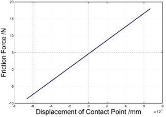
a) Stick ( 45°)
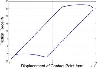
b) Slip but no liftoff ( 45°)
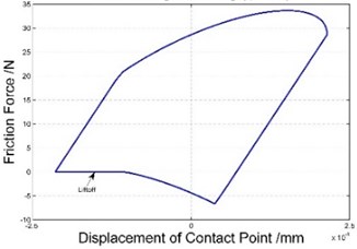
c) Liftoff during unloading ( 45°)
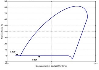
d) Liftoff during unloading and reloading ( 45°)
5. Calculate equivalent stiffness and equivalent damping using HBM method
After getting the hysteresis curves, the equivalent damping and equivalent stiffness is analyzed using HBM method.
Suppose the displacement of contact point changes harmonically: .
The damper’s friction force can be expressed using equivalent damping and equivalent stiffness as:
The damper’s friction force can also be expanded in Fourier series and truncated after its fundamental terms:
Compare Eq. (3) and Eq. (4), one can get the expressions of equivalent damping and equivalent stiffness:
Thus, with the presence of hysteresis curves, one can use Eq. (5) to calculate damper’s equivalent damping and equivalent stiffness and further more analyze the vibratory response of shrouded blade.
Fig. 4 shows how equivalent damping varies along with vibration amplitude in macroslip models under the conditions of linearly (0°) and non-linearly (45°) variable normal load. As can be seen, in both models, varying pattern of equivalent damping is the same: when amplitude is smaller than a certain value, the contact surface sticks and equivalent damping stays as 0; when amplitude is getting larger, equivalent damping increases dramatically to maximum value and then decreases gradually. Compared with linearly variable normal load model, the equivalent damping is larger when normal load varies non-linearly; and the bigger the amplitude is, the larger the difference is.
Fig. 5 contains a series of curves showing how equivalent damping changes when phase difference is different. It is shown that for each value of , varying pattern of equivalent damping is the same, but as increases, the maximum value of equivalent damping increases first and then decreases. At the same time, with larger , the “tail” of curve is more flat, which means with increasing amplitude, equivalent damping decreases less sharply.
Fig. 4Equivalent damping varying along vibration amplitude
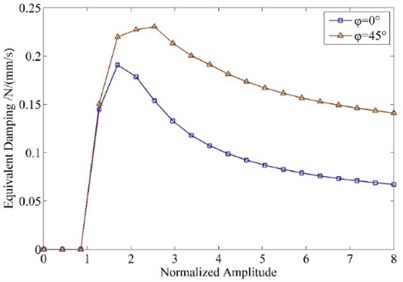
Fig. 5Equivalent damping varying along vibration amplitude of different φ
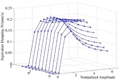
Fig. 6Equivalent stiffness varying along vibration amplitude
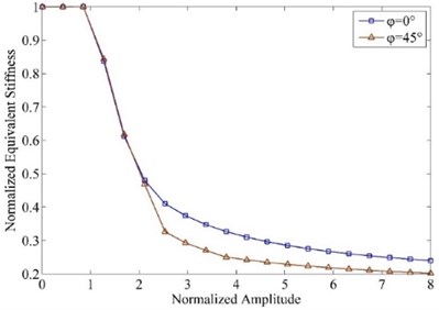
Fig. 7Equivalent stiffness varying along vibration amplitude of different φ
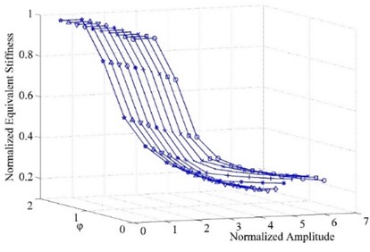
Fig. 6 shows how equivalent stiffness varies along with vibration amplitude in macroslip models under the conditions of linearly (0°) and non-linearly (45°) variable normal load. As shown in the figure, in both models, varying pattern of equivalent stiffness is the same: when amplitude is smaller than a certain value, the contact surface sticks and equivalent stiffness keeps constant and equal the contact stiffness which is the maximum value of equivalent stiffness; when amplitude is getting larger, equivalent damping decreases but the change rate gets smaller and smaller. Compared with linearly variable normal load model, the equivalent stiffness is smaller when normal load varies non-linearly.
Fig. 7 contains a series of curves showing how equivalent stiffness changes when phase difference is different. It is demonstrated in the figure that for each value of , varying pattern of equivalent stiffness is the same, but as increases, the minimum value of equivalent stiffness decreases and the bigger is, the steeper the curve is, which means equivalent stiffness decreases more dramatically when phase difference is larger.
6. Experimental verification
The vibratory response of the shrouded blade structure was analyzed using the non-linearly variable normal load macroslip model raised above, and analyzed results were compared with the experimental data in reference [14].
Fig. 8 shows the comparison of calculated results and experimental date. Compared to the results got using linearly variable normal load model, those by non-linearly variable normal load model are closer to tested data. The reason is that when normal load is considered as non-linearly variable, the corresponding equivalent damping is larger, which means damper dissipates more energy and leads the calculated vibratory response amplitude smaller and closer to the experimental data as a result. So it is reasonable to conclude that the non-linearly variable normal load model can simulate practical conditions more precisely.
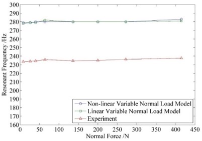
Fig. 9 compares the calculated resonant frequencies and those tested in experiment. The resonant frequencies calculated using two models are basically identical (about 280 Hz), while the tested resonant frequencies are approximately 40 Hz lower. The reasons contributing to this difference include but are not limited to: 1) In calculation, the systems boundary conditions are supposed to be ideally rigid and only the vibration of blade is taken into consideration which cannot be true in reality; 2) Practically, values of parameters such as contact stiffness, friction coefficient might change, while all the parameters are treated as constant value in calculation.
Fig. 8Response amplitude of different initial normal load
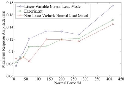
Fig. 9Resonant frequency of different initial normal load
7. Conclusions
In vibration process of shrouded blade, the motion component vertical to contact surface leads normal load to vary, and the variation are normally non-linear because of the existence of phase difference between adjacent blades. This article analyzed the influence of non-linearly variable normal load on damper’s vibration-reducing effect. Using the model raised, this article calculated the vibratory response of a shrouded blade structure and compared the result with experimental data. The main conclusions are as following:
1) Due to the phase difference existing between adjacent blades, normal load on the contact surface varies non-linearly during vibration, and this kind of non-linearity will effect damper’s vibration-reduction function;
2) The hysteresis curves derived from non-linearly variable normal load macrolip model can simulate all possible states occurring on contact surface, including stick, slip and separation;
3) The calculated results using non-linearly variable normal load macrolip model are closer to the tested data, which indicates the non-linear model raised in this article can better reflect shrouded blade structure’s physical essence and simulate structure’s practical vibration more precisely.
References
-
Griffin J. Friction Damping of resonant stresses in gas turbine engine airfoils. Journal of Engineering for Gas Turbines and Power, Vol. 102, Issue 2, 1980, p. 329-333.
-
Sinha A., Griffin J. Effects of static friction on the forced response of frictionally damped turbine blades. Journal of Engineering for Gas Turbines and Power, Vol. 106, Issue 1, 1984, p. 65-69.
-
Griffin J., Sinha A. The interaction between mistuning and friction in the forced response of bladed disk assemblies. Journal of Engineering for Gas Turbines and Power, Vol. 107, Issue 1, 1985, p. 205-211.
-
Chen J., Yang B., Menq C. Periodic forced response of structures having three-dimensional frictional constraints. Journal of Sound and Vibration, Vol. 229, Issue 4, 2000, p. 775-792.
-
Cigeroglu E., Lu W., Menq C.-H. One-dimensional dynamic microslip friction model. Journal of Sound and Vibration, Vol. 292, Issue 3, 2006, p. 881-898.
-
Hao Yanping, Zhu Zigen New method to resolve vibratory response of blades with friction damping. Acta Aeronautica et Astronautica Sinica, Vol. 22, Issue 5, 2001, p. 411-414, (in Chinese).
-
Shan Yingchun, Zhu Zigen, Liu Xiandong Investi-gation of the vibration control by frictional constraints between blade shrouds-theoretical method. Journal of Aerospace Power, Vol. 21, Issue 1, 2006, p. 168-173, (in Chinese).
-
Shi Yajie, Shan Yingchun, Zhu Zigen Analysis of nonlinear response of shrouded blades system. Journal of Aerospace Power, Vol. 24, Issue 5, 2009, p. 1158-1165, (in Chinese).
-
Griffin J., Sinha A. The interaction between mistuning and friction in the forced response of bladed disk assemblies. Journal of Engineering for Gas Turbines and Power, Vol. 107, Issue 1, 1985, p. 205-211.
-
Wang J.-H., Chen W. Investigation of the vibration of a blade with friction damper by HBM. Journal of Engineering for Gas Turbines and Power, Vol. 115, Issue 2, 1993, p. 294-299.
-
Sanliturk K., Imregun M., Ewins D. Harmonic balance vibration analysis of turbine blades with friction dampers. Journal of Vibration and Acoustics, Vol. 119, Issue 1, 1997, p. 96-103.
-
Yang B.-D., Menq C.-H. Modeling of friction contact and its application to the design of shroud contact. Journal of Engineering for Gas Turbines and Power, Vol. 119, Issue 4, 1997, p. 958-963.
-
Yang B., Chu M., Menq C. Stick–slip–separation analysis and non-linear stiffness and damping characterization of friction contacts having variable normal load. Journal of Sound and Vibration, Vol. 210, Issue 4, 1998, p. 461-481.
-
Hong Jie, Shi Yajie, Liu Shuguo, et al. Experiment of damping characteristic of non-rotating shrouded blade. Journal of Beijing University of Aeronautics and Astronautics, Vol. 32, Issue 10, 2006, p. 1174-1179, (in Chinese).
About this article
