Abstract
Wooden component has been used extensively in industries and the sound insulation performance of these components will directly be associated with the noise problem. We used sound pressure method and sound intensity method separately to measure the transmission loss of wood component, their results were in good agreement through the entire frequency band and the differences between them are in reasonable engineering error range. Test failures have been avoided by this as well as providing some protection for the subsequent simulation validation. After that, the damping loss factor of wood component has been measured by pulse attenuation method and imported into AML model to calculate the transmission loss, compared to experiment results, they were in good agreement, which indicates this kind of simulation method is available in the prediction of the acoustic performance for wooden component. Various technique means have been used to optimize the sound insulation performance, such as changing the density, elastic modulus, thickness of wooden component and surface treatment and sound package, and the results show that all the optimization programs can be effective in the improvement of sound insulation performance. At last, all the optimization data was arranged and compiled into a database, through the operation of the database interface, it is easy to select any group of data to draw graphics. This database provides an effective way to develop the optimal program of wooden component which has the best sound insulation performance.
1. Introduction
In recent years, the wood industry are in great development and its application has been expanded to such area as automobile, architecture and high-speed train. The research on wooden component are focused on such aspects like preseveration and manufacture processing. For instance, Professor Li Hua and his colleagues explored how to filter the indoor wooden floor and the medicine to help its preservation [1], Professor Li Yudong pointed out that the antiseptic is an effective measure to prolong the life of wooden component [2] and Professor Gu Lianbai explored the applicaiton of Ultra-high-temperature heat treatment process on wooden component [3]. Kamdem researched durbility of the heat-treated wood [4].
The research on acoustic problems of wooden component are simple and obvious. The book “Wood Acoustics” also studied the sound absorption coefficient of wood theoretically [5] and didn’t mention the sound insulation performance.
The study on the acoustic characteristics of wooden component is based on a high-speed train project. We used sound pressure method and sound intensity method separately to measure the transmission loss of wood component, their results were in good agreement through the entire frequency band and the differences between them are in reasonable engineering error range. Test failures have been avoided by that as well as providing some protection for the subsequent simulation validation. A series of effective optimization plans to improve sound insulation has been made, which also have reference values in engineering application. All the optimization data was arranged and compiled into a database, through the operation of the database interface, it is easy to select any group of data to draw graphics. This database provides an effective way to develop the optimal program of wooden component which has the best sound insulation performance.
2. Experiment of the transmission loss
The definition of transmission loss is the ratio of test piece’s incident sound power and its transmission sound power (then takes its logarithm based on 10 and multiplied by 10). The unit of sound insulation is dB [6]:
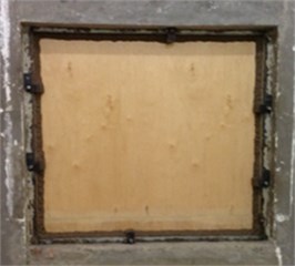
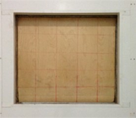
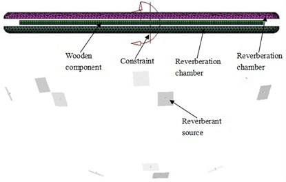
As shown in Fig. 1, the wooden component has been fixed in the reverberation chamber. The gaps between these two chambers have been filled with sludge. Sound pressure method and sound intensity method have been used separately to measure transmission loss of these two wooden component, in order to avoid mistakes during the experiment and to provide some protection for the subsequent simulation validation.
Fig. 1The experiment of the transmission loss
a) Incident side
b) Transimission side
2.1. Sound pressure method
In this equation, is the average number of SPL (Sound Pressure Level) inside the reverberation chamber of the incident side; is the average number of SPL inside the reverberation chamber of the transmission side; is the unilateral surface area of the wooden component; is the number of sound absorption inside the reverberation chamber of the transmission side.
According to ISO354 [7], the number of sound absorption can be calculated by Sabine formula, shown as follows:
where is the volume of the reverberation chamber; is the reverberation time of the reverberation chamber.
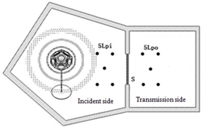
Depending on the size of the laboratory room, four microphones have been arranged separately and symmetrically surrounding the test piece of wooden component. In order to observe the uniformity of diffuse sound field, another microphone has been added in the center of these four microphones, as shown in Fig. 2. During the experiment, pink noise sound source was added in the incident side; after the formation of a stable reverb, simultaneous measurement of SPL of each microphone position was started. Each group of data was recorded for 8 s, measured three times, and the sampling frequency was 65536 Hz. Finally, the average SPL of these five-points was chosen as the incidence SPL and transmission SPL.
Fig. 2The test schematic of sound pressure method
The reverberation time has been tested after that. The reverberation time is the time required between sound source stops sounding and the acoustic energy density indoor falls to 60 dB. Keep the microphone position in the transmission side to be the same and add the same pink noise sound source. During the experiment, pink noise has been given for 3 s at first; after the sound source stopped sounding, the SPL decay process was measured immediately. Each group of data was recorded for 8 s and measured three times; the sampling frequency was 65536 Hz. The reverberation time was taken into Eq. (3) to calculate the sound absorption.
The incidence SPL and transmission SPL, the sound absorption (obtained by the experiment) were taken into Eq. (2) to calculate the sound insulation of these wooden components.
2.2. Sound intensity method
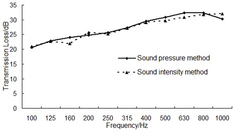
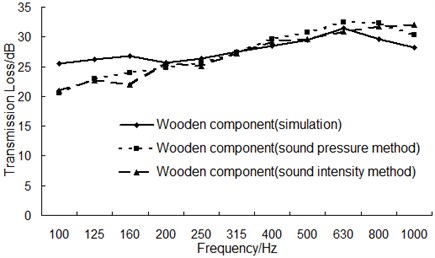
Fig. 3The comparison for the transmission loss of two kinds of method
In order to verify the accuracy of sound pressure method, we also used sound intensity method in this experiment. The sound intensity method include two procedure, one is to measure the average SPL of five-points in the incident side (like the measure process of sound pressure method), the other one is to obtain the radiation sound intensity of test pieces through using sound intensity probe to do near-field surface scanning of the specimen in the transmission side. The sound insulation calculating formula of sound intensity method is as follows:
Compare transmission loss obtained by these two kinds of method, the result is shown in Fig. 3.
As can be seen from Fig. 3, the results have a good agreement measured by these two kinds of method separately. It indicates that there was no presence of errors during the experiment and the test results are reliable.
3. Simulation of the transmission loss
During the numerical simulation of transmission loss, in order to simulate the actual condition accurately, the damping loss factor would be measured in the experiment and imported into the software.
3.1. Damping loss factor measurement
The definition of damping loss factor is the ratio of energy consumption caused by system damping property and the whole energy storage of the system, consists of three independently loss factor [8]:
where is the structure loss factor caused by the interior friction of system material; is the loss factor caused by the sound radiation damping of system vibration; is the loss factor caused by connection damping of system boundary.
In this measurement, pulse attenuation method [9, 10] has been used to measure the damping loss factor of the test pieces; the test device is shown in Fig. 4. As is shown in Fig. 4, the test piece chosen is rectangular plate. When a rectangular plate subjects to a lateral force, several bending vibration will come into existence; the vibration formula can be written as follows [11, 12]:
where is the particular solution to a given excitation force; is the angular frequency of harmonic vibration in mode; phase angle and fixed coefficient will be determined by the initial condition when the plate vibrates; is the corresponding attenuation factor.
The information of plate vibration was measure by vibration acceleration sensors. For a given mode of vibration, the acceleration signal decayed exponentially; is the slope of this envelope decay curve.
The signal processing method of this trial was to perform an FFT transform towards the acceleration signal to obtain the angular frequency of each harmonic vibration at first. Then with the help of Butterworth band pass filter, several free-damped vibrations corresponding to each harmonic vibration mode would be isolated as follows:
After that, through taking square and taking natural logarithm, a new signal would be obtained from the filtered signal:
Finally, polynomial fitting would be done towards the new time-domain signal curve; the corresponding decay factor would then be determined by the slope of the fitting curve; the damping loss factor of the rectangular plate could be calculated by the following equation:
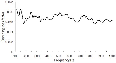
During the measurement, each test piece has 6 vibration test points and 30 hammer attack points. Each test point recorded 10 s vibration decay process at one time and the whole measurement process has been done for 3 times; the sampling frequency was 16384 Hz. The damping loss factor of this wooden component is shown in Fig. 5.
Fig. 4The test schematic diagram of damping loss factor
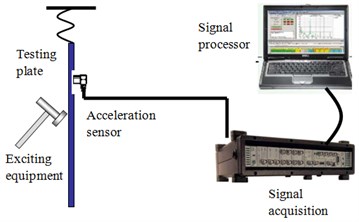
Fig. 5Damping loss factor of the wooden component
3.2. Simulation model establishment
Two sound cavities have been established on both sides of the wooden component to simulate the actual reverberation chambers. Compared to the traditional finite element method, the calculating efficient of AML is relatively high. In AML, transmission loss can be extracted directly, without the need to acquire an indirect calculation. The final 3D model is shown in Fig. 6.
Fig. 6AML simulation model of the transmission loss
The comparison between the experiment transmission loss and the simulation was shown in Fig. 7.
As can be seen from Fig. 7, in the low frequency range below 160 Hz, the simulation results have a relatively large difference with experiment results and the maximum difference is 5 dB. This phenomenon was mainly caused by boundary condition differences between simulation process and the experiment.
During the experiment, the boundary condition is shown in Fig. 1, in which the wooden component was fixed by multi-point constraints and all-around was sealed with sludge. However, the simulation process could only simplified the actual boundary conditions instead of maintain full consistency with the experiment.
Fig. 7The comparison between experiment and simulation of the transmission loss
In the high frequency range above 160 Hz, boundary conditions no longer play a dominant role and thus these two kinds of result have a good agreement. In summary, the overall simulation trend is consistent with experiment, which indicates AML method is effective in predicting the sound insulation performance of wooden component.
4. Optimization of the transmission loss
Through several kinds of technical means such as changing the density, thickness of wooden component, surface treatment and sound package, transmission loss of wooden component has been optimized.
4.1. Surface treatment
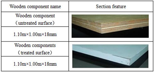
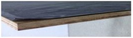
A layer of organic polymer material has been sprayed on the surface of wooden component, as shown in Fig. 8.
Fig. 8The sectional view for wooden component before and after surface treatment
Transmission loss of this wooden component before and after surface treatment has been tested and compared in Fig. 9.
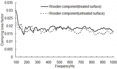
As can be seen from Fig. 9, the surface treatment makes transmission loss of wooden component increase about 1 dB throughout the whole frequency band. In order to further analyze the reasons for this phenomenon, the damping loss factor for wooden component before and after surface treatment has been measured, as shown in Fig. 10.
As can be seen from Fig. 10, the damping loss factor for wooden component after surface treatment has an apparently increase, which would improve the sound insulation of wooden component to some extent.
Fig. 9The transmission loss for wooden component before and after surface treatment
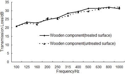
Fig. 10Damping loss factor for wooden component before and after surface treatment
4.2. Sound package
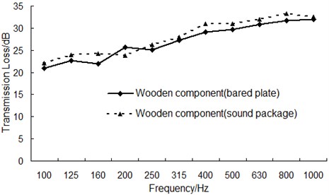
A 1 mm thick layer of rubber material has been affixed to one side of wooden component, as shown in Fig. 11; transmission loss then was measured and compared to the bare board before, as shown in Fig. 12.
Fig. 11The sound package of wooden component
As can be seen from Fig. 12, after affixing a 1 mm thick layer of rubber material, the sound insulation of wooden component increases about 2 dB throughout the whole frequency band, because rubber has good viscoelastic which can effectively decay vibration and improve sound insulation performance.
Fig. 12The transmission loss curve before and after the sound package
4.3. Change the thickness of wooden component
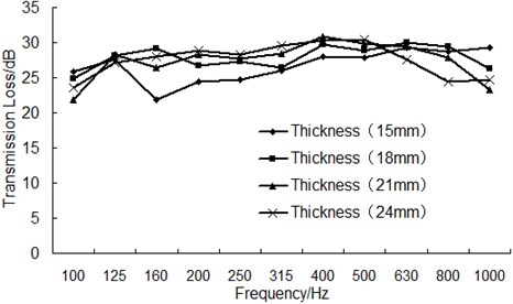
While the material properties of wooden component were remained unchanged, the thickness of wooden component was changed from 15 mm to 24 mm (the step length is 3 mm); the transmission loss curves under different thickness have been obtained and shown in Fig. 13.
As can be seen from Fig. 13, with the increase of thickness, transmission loss shows a rising trend in the frequency band under 500 Hz; however, transmission loss decreases in general with the increase of thickness in the frequency band between 500 Hz and 1000 Hz.
The average transmission loss under each thickness has been calculated to be 26.03 dB, 26.84 dB, 27.05 dB and 27.51 dB. This result showed that the average transmission loss had small changes when the thickness increased from 18 mm to 24 mm. Therefore, it’s recommended to set the thickness of wooden component to 18 mm to avoid increasing weight and reducing product performance.
Fig. 13The comparison of the transmission loss for wooden component with different thickness
4.4. Change the elasticity modulus of wooden component
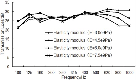
While other parameters of wooden component remained unchanged, the elasticity modulus was changed from 3.0×10⁹ Pa to 7.5×10⁹ Pa (the step length is 1.5×10⁹ Pa); the transmission loss curves under different elasticity modulus have been obtained and shown in Fig. 14.
As can be seen from Fig. 14, with the increase of elasticity modulus, the general trend of transmission loss is not clear in the frequency band under 500 Hz; mainly because it’s in the area of quality control at this time where the sound insulation performance is mainly controlled by overall quality and the change of elasticity modulus doesn’t affect the quality itself. On the other hand, transmission loss decreases apparently with the increase of elasticity modulus in the frequency band between 500 Hz and 1000 Hz, because transmission loss is no longer controlled by quality in this area.
The average transmission loss under each elasticity modulus has been calculated to be 27.47 dB, 26.84 dB, 25.92 dB and 25.41 dB. This result showed that the average transmission loss decreased when the elasticity modulus increased from 3.0×10⁹ Pa to 7.5×10⁹ Pa while the rigidity of wooden component is reduced gradually at the same time. Therefore, considering rigidity and sound insulation performance, it’s recommended to choose the wooden component whose elasticity modulus is 4.5×10⁹ Pa.
Fig. 14The comparison of the transmission loss for wooden component with different modulus
4.5. Change the density of wooden component
While the elasticity modulus and thickness of wooden component remained unchanged, the density of wooden component was changed from 500 kg/m3 to 800 kg/m3 (the step length is 100 kg/m3); transmission loss curves under different density have been obtained and shown in Fig. 15.
Fig. 15The comparison of the transmission loss for wooden component with different density
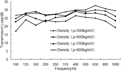
As can be seen from Fig. 15, with the increase of density and frequency, transmission loss shows an apparently rising trend in the frequency band under 630 Hz; however, the transmission loss decreases in general with the increase of frequency above 630 Hz. On the other hand, the transmission loss also shows a slow rising trend with the increase of density in the frequency band above 630 Hz.
The average transmission loss under each density has been calculated to be 22.63 dB, 24.99 dB, 26.94 dB and 27.96 dB. This result showed that the average transmission loss increased when the density increased from 500 kg/m3 to 800 kg/m3 while the rate of increase reduced. Therefore, considering the lightweight and sound insulation performance request, it’s recommended to choose the wooden component whose density is 700 kg/m3.
Fig. 16The graphics interface of the datebase for sound insulation performance
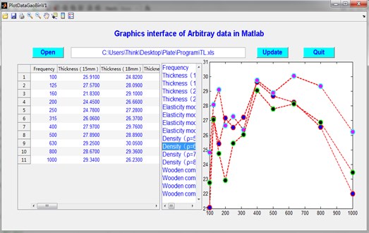
5. Optimization database of the transmission loss
The optimization above for transmission loss of wooden component is just limited to the comparison of the same class. As for what kind of relationship will be shown between the comparison of several different categories, according to permutations and combinations, hundreds of graphics could be drawn. In order to make it convenient, all the optimization data has been arranged and compiled into a database.
We can enter the graphics interface, as shown in Fig. 16. In the graphics interface, you can choose any group of the optimization data above to draw graphics which is not only convenient but also rather fast. This database provides an effective way to develop the optimal plan of wooden component which has the best sound insulation performance.
6. Conclusions
1) Sound pressure method and sound intensity method have been used separately to measure the transmission loss of wooden component. Their results were in good agreement through the entire frequency band and the differences between them are in reasonable engineering error range, successfully avoiding mistakes during the experiment and providing some protection for the simulation validation.
2) Pulse attenuation method has been used to measure the damping loss factor of wooden component and import into AML model to calculate the sound insulation. Compared to experimental results, they were in good agreement, which indicates that this kind of simulation method is available in the prediction of the acoustic performance of wooden components.
3) Various technique means have been used to optimize the sound insulation performance, such as changing the density, elastic modulus, thickness of wooden component, surface treatment and sound package. The results showed that all the optimization plans could be effective in the improvement of sound insulation performance.
4) All the optimization data has been arranged and compiled into a database. Through the operation of the database interface, you can easily select any group of data to draw graphics. This database provides an effective way to develop the optimal plan of wooden component which has the best sound insulation performance.
References
-
Li H., Liu X. Y., Chen Y. S. An experiment on selecting antifungal and anti-insect agents for indoor wood-based flooring and other wood products. China Wood Industry, Vol. 3, 2004, p. 11-15.
-
Li Y. D. Preservation – an effective measure of extending the service life of wood. China Wood-Based Panels, Vol. 3, 2001.
-
Lian B., Tao Li G. U., Deng-Yun T. U., Ning J. I. A. N. G. Technology and application on heat-treated solid wood flooring. China Wood Industry, Vol. 3, 2007.
-
Kamdem D. P., Pizzi A., Jermannaud A. Durability of heat-treated wood. European Journal of Wood and Wood Products, Vol. 60, Issue 1, 2002, p. 1-6.
-
Bucur V. Acoustics of Wood. Springer, 2006.
-
Du G. H., Zhu Z. M., Gong X. F. Basics Acoustic. The Press of Nanjing University, 2001.
-
Iso standart. Acoustics – Measurement of sound absorption in a reverberation room, 2003.
-
Chen X. Research on analysis and control of car interior noise based on SEA bethod. The Institute of Automotive Engineering, Jilin University, 2008.
-
Bolduc M., Atalla N. Measurement of SEA damping loss factor for complex structures. The Journal of the Acoustical Society of America, Vol. 123, Issue 5, 2008, p. 3060-3060.
-
Zhang H. L., Kong X. R., Liu Y., et al. Test identification of damping loss factor in a wider frequency range. Journal of Vibration and Shock, Vol. 32, Issue 12, 2013, p. 179-184.
-
Zhao Y. Y., Sheng S. W. Measurement of attenuation factors for damped vibration of thin-shell structures. Journal of Tongji University, Vol. 30, Issue 7, 2002, p. 900-903.
-
Morse P. M. Theoretical Acoustics. Princeton University Press, 1986.
About this article
The financial supports from the National Natural Science Foundation (Grant No. 11272159, 11172099) and Jiangsu Overseas Research and Training Program for University Prominent Young and Middle-aged Teachers and Presidents of China are acknowledged.
