Abstract
The operating frequencies of the vibroactive pad used in order to improve the quality of replicas of complex microstructures during the mechanical hot imprint process, are numerically analyzed in this paper. It is known that piezoceramics (and in the same time all construction) change its dynamical properties under the action of mechanical load. It is necessary to investigate dynamical properties of vibroactive pad, in order to improve the quality of replicas when planning more detailed research and development in this field in the future. Experimentally there is no possibility to determine the frequency for the construction to be excited, in order to reach modes of forms, thus modeling of the process was performed. The created mathematical model of vibroactive pad was implemented by FEM using COMSOL Multiphysics software. The vibroactive pad’s numerical analysis was performed with and without the action of mechanical load, as well experimental verification of model was performed (for the validation of the model without load with experimental data).
1. Introduction
The exceptional potential of hot imprint technology like: low cost, easy implementation and ability to obtain high resolution are the main reasons for further investigation, establishment and application of such manufacturing capabilities. The basic principle of hot embossing composes from following major steps: first of all polymer substrate is heated above its glass transition temperature. Then a mold (or master) is pressed against the substrate. Lastly, the system is cooled down below glass transition temperature, and the embossed substrate is demolded from the tool. On the other hand there is necessity to study the risk of formed microstructure potential defects, which can occur as the result of material melting and releasing of the structure from the mold. These defects include material shrinkage, visible cracks, etc. One of the ways to improve the quality of replicas can be usage of high-frequency vibrations in the process of mechanical hot imprint. Ultrasonic vibrations [1-4] are widely applied in industrial processes, especially in welding and joining of thermoplastic with low softening temperature.
Ultrasonic vibrations during the process of hot imprint help diminish or completely avoid bubble defect in the pattern. It is also revealed that ultrasonic vibrations forced softened polymer to move to the center of the pattern area. The effect of ultrasonic vibrations asserts better under the action of lower contact force, because high contact force may inhibit amplitudes of ultrasonic vibration [5].
As it is revealed high frequency vibrations can be used as a measure to improve the quality of replicas [6], on the other hand it is necessary to know working regimes of the equipment, which generates such vibrations, in this case working regimes of vibroactive pad. To perform such an analysis experimentally is impossible, so it was decided in this paper to create model of vibroactive pad and analyze this pad using Comsol Multiphysics software (with and without the action of mechanical load) [7, 8]. Later on, the results of numerical analysis are compared with real construction (without mechanical load (since with load it would be impossible to observe vibration modes), when observing it with holographical inferferometer – PRISM).
2. Finite element model of vibroactive pad
Modeling of vibroactive pad used in hot imprint process as frequency generator is presented in this section.
Aluminum cylinder with the top surface and a mounting hole in the side wall was chosen as a vibrating pad. The drawing of the vibrating pad with the mounted piezoelectric element is shown in the Fig. 1.
Fig. 1The 3D view of the pad (1) with the piezoelectric element (2)
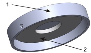
The applicability of vibroactive pad vibration in the process of hot imprinting was analyzed numerically using finite element method. The dynamic parameters of the vibroactive pad (Fig. 1) were calculated using program COMSOL Multiphysics 3.5a. Dynamic research of vibroactive pad was carried out under different conditions: without mechanical load and with load in the center of vibroactive pad.
The geometrical parameters of vibroactive pad are: vibroactive pad thicknesses () is 2 mm, thickness of piezo ceramic ring is 3 mm, and total height of the vibroactive pad is 10 mm. It is necessary to determine boundary conditions and initial value of the parameters of the model. Vibroactive pad’s bottom surface is fixed (Fig. 2). Potential difference according to the experimental results between the upper and the lower piezoceramic ring surfaces vary from 5 to 150 V. The computational scheme of vibroactive pad is presented in Fig. 2.
Fig. 2Computational scheme of vibroactive pad (displacement (u, v, w), thickness of vibroactive pad (hAl), thickness of piezo ceramic ring (hPZT) and height of vibroactive pad (h))
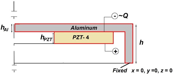
Fig. 3Tetrahedral finite element [9]
![Tetrahedral finite element [9]](https://static-01.extrica.com/articles/14762/14762-img3.jpg)
The pad’s material is aluminum (D16) and the disk is modeled as a piezo ceramic material PZT-4. The PZT-4 material’s and aluminum’s parameters were chosen from Comsol Multiphysics material library.
Quadratic tetrahedral finite element (which has ten nodes and four dependent variables in each node (displacements in , , directions and voltage )) was chosen for modeling (Fig. 3).
The material parameters for the piezoelectric material were specified according to: selecting the stress-charge form based on the constitutive equation and entering the material data (the elasticity-matrix elements in the matrix, the piezoelectric coupling-matrix elements in the e matrix, and the relative permittivity in the matrix). The material properties in this model were set considering that the polarization is in the z direction, which is a common orientation, according to the literature.
Elasticity matrix: The elasticity matrix defines the stress-strain relation, and is denoted as matrix :
where is stress, and is strain,
Coupling matrix: The coupling matrix defines the piezo coupling matrix e, used in the stress-charge form of the constitutive equation:
where is stress, – strain, and is the electric field,
Relative permittivity: The relative permittivity appears in the constitutive relation on stress-charge and strain-charge forms, respectively:
.
Piezoelectric FEM equations can be written in terms of nodal displacement and nodal electrical potential for each node.
where is mechanical stiffness matrix, is piezoelectric coupling matrix, is dielectric stiffness matrix, is mass matrix, is piezoelectric density, is matrix of elemental shape functions, is mechanical damping matrix, , is derivatives of FEM shape functions, is elastic coefficients, is piezoelectric coefficients, is dielectric coefficients, is damping coefficient, is external mechanical effect and is electrical effect.
The understanding of the resonance characteristics of vibroactive pad can be investigated by visualizing the displacement, generated in the structure at resonant frequencies, which provide the resulting modal shapes. It is needed to solve eigenvalue problem. The analysis consists of two steps: static analysis and eigenvalue analysis. The first step was static analysis for different electrical potential and the pressure was equal to zero.
The second step was eigenvalue analysis of deformed vibroactive pad:
The next step is to create finite element model of vibroactive pad, when it is under the action of mechanical load. Thus the model was modified, by adding additional load (Fig. 4).
Fig. 4Modified vibroactive pad (1) with sample (2) and pressure tool (3)
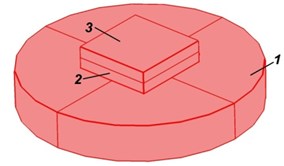
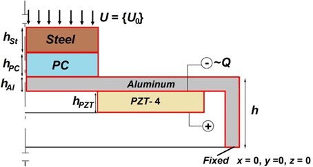
A 20×020 mm sample of polycarbonate and the pressure tool are projected in the middle of the vibroactive pad (Fig. 5.). The pressure device is modeled as non-deformable very stiff isotropic body from structural steel. Material properties of sample of polycarbonate and pressure tool were taken from COMSOL Multiphysics library (Table 1.). The thicknesses of steel () and polycarbonate () are 3 mm. The pressure is defined as displacement () of upper steel’s plane by axis.
The full analysis consists also of two steps: static analysis and eigenvalue analysis. The first step was static analysis for different pressure .
The second step was eigenvalue analysis of deformed vibroactive pad:
Table 1Material properties
Material properties | Polycarbonate | Structural steel |
Young modulus, Pa | 2*109 | 200*109 |
Poisson’s ratio | 0.37 | 0.33 |
Density, Kg/m3 | 1200 | 7850 |
Fig. 5Computational scheme of vibroactive pad with load (displacement (u, v, w), thickness of vibroactive pad (hAl), thickness of piezo ceramic ring (hPZT), thickness of specimen (hPC), thickness of pressure horn (hSt) and height of vibroactive pad (h))
3. Results
Frequencies of modes of vibrations were compared in order to check the validity of vibroactive pad modeling results with experimental data.
Numerical simulation results of vibroactive pad working at different regimes are presented in Fig. 6.
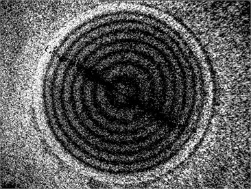
In order to determine the validity of mathematical model, it was compared with experimental results. The same vibration modes were obtained experimentally using the PHASE III PRISM system (measurement resolution – 20 nm, measurement range – 100 µm, largest part size – 1000 mm, working distance >1.3 m, data acquisition rate – 30 Hz, laser power – 20 mW, laser wavelength – 532 nm), produced by Hytec Company [10-12]. Vibration modes of made vibroactive pad (without load) are presented in (Fig. 7).
The comparison between the experimental research (Fig. 7) and simulation results (Fig. 6) shows that simulation results corresponds experimental results of vibroactive pad. The calculated difference of vibration frequency between experimental and simulated results was 5.4 % (the first form), 7.9 % (the second form), and 28.7 % (the third form). As it can be seen from the results, mathematical model is valid, and can be used for further analysis.
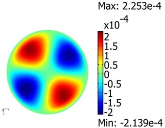
The next step of the investigation is to find operating frequencies of the vibroactive pad, when it is under load of 5.06·105 Pa. For the development of vibroactive pad, which could be applied in the mechanical hot imprint process, it is useful to know vibration frequencies for corresponding modes under the pressure of vibroactive pad’s surface. It is impossible to observe vibration modes by using holographic interferometer, since loading device would cover the surface, which interests us, so the only way is to rely on numerical results. All these modes allow to achieve various optical properties of microstructure. The initial mathematical model (without load) of vibroactive pad was modified. The pressure as constrain displacement was added to the center of the pad. Pressure parameters are applied to area of the sample (20×20 mm). The vibration modes of vibroactive pad under the pressure of 5.06·105 Pa are presented in the Fig. 8.
Fig. 6Vibration modes of model of vibroactive pad (without load): a)5.8 kHz and 10 V, b) 9.5 kHz and 60 V, c) 19.3 kHz and 70 V
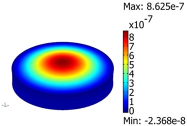
a)
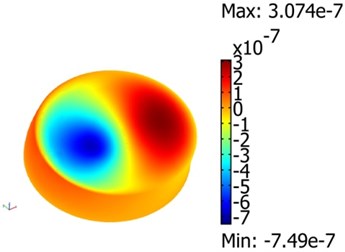
b)
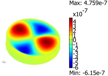
c)
Fig. 7Vibration modes of made vibroactive pad (without load): a) 5.2 kHz and 5 V, b) 8.8 kHz and 40 V, c) 15 kHz and 40 V
a)
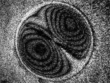
b)
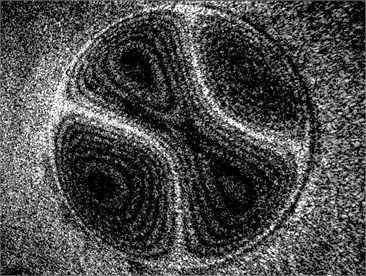
c)
The obtained results show, that the same vibration modes require higher frequencies. The frequency should be increased approximately by 20 % (the first and the second forms), in order to get the same vibration mode, as it would be without pressure.
Fig. 8Modes of vibroactive pad at 5.06⋅105 pressure: a)7 kHz and 10 V, b) 11.7 kHz and 60V, c) 19.9 kHz and 70 V
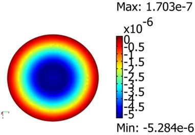
a)
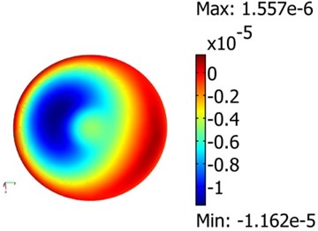
b)
c)
4. Conclusions
In this paper vibroactive pad made from aluminum was numerically analyzed in order to determine its working regimes. Three vibration modes, natural frequencies and operating voltages of vibroactive pad were determined both numerically and experimentally. First three natural frequencies of modeled vibroactive pad are as following: 5.8; 9.5 and 19.3 kHz and experimental results for the same vibration modes are: 5.2; 8.8; and 15 kHz respectively. Difference between the results, which were obtained by analyzing the pad experimentally and numerically does not exceed 28.7 %, thus confirming the validity of mathematical model, and enabling to perform further numerical analysis of mechanically loaded pad. According to further numerical analysis, the frequency of vibroactive pad with applied mechanical load (5.06·105 Pa pressure) at the center should be increased by about 20 %, i.e. first mode – 7 kHz, second mode – 11.7 kHz and third mode – 19.9 kHz in order to get the same vibration modes as it would be without load.
References
-
Benatar A., Gutowski T. G. Ultrasonic Welding of PEEK Graphite APC-2 Composites. Polymer Engineering and Science, Vol. 29, Issue 23, 1989, p. 1705-1721.
-
Nonhof C. J., Luiten G. A. Estimates for process conditions during the ultrasonic welding of thermoplastics. Polymer Engineering and Science, Vol. 36, 1996, p. 1177-1183.
-
Liu S. J., et al. Development of Weldability Diagrams for Ultrasonic Welding of Thermoplastics in Far-Field. Plastic Rubber Composite Processing and Applications, Vol. 27, Issue 6, 1998, p. 279-286.
-
Liu S. J., Chang I. T., Hung S. W. Factors affecting the joint strength of ultrasonically welded polypropylene composites. Polymer Composites, Vol. 22, Issue 1, 2001, p. 132-141.
-
Mekaru H., Goto, H., Takahashi M. Development of ultrasonic micro hot embossing technology. Microelectronic Engineering, Vol. 84, 2007, p. 1282-1287.
-
Narijauskaitė B., Palevičius A., Narmontas P., Ragulskis M., Janušas G. High-frequency excitation for thermal imprint of microstructures into a polymer. Experimental Techniques. Malden: Wiley-Blackwell Publishing, Vol. 37, Issue 5, 2013, p. 41-47.
-
Gaidys R., Narijauskaitė B., Palevičius A., Janušas G. Numerical simulation of hot imprint process of periodical lamellar microstructure in to polycarbonate. Micromachining and microfabrication process technology XVII, Bellingham: SPIE, Vol. 8248, 2012, p. 1-9.
-
Janušas G., Palevičius A., Palevičius R. Some methodological aspects of usage COMSOL multiphysics in teaching fundamentals of computational mechanics. Global Cooperation in Engineering Education: Innovative Technologies, Studies and Professional Development: the 3rd international conference proceedings, Kaunas, Technologija, 2009, p. 151-156.
-
McCaslin S. E., et al. Closed-form stiffness matrices for higher order tetrahedral finite elements. Advances in Engineering Software, Vol. 44, Issue 1, 2012, p. 75-79.
-
Bansevičius R. P., Telksnytė S., Janušas G., Palevičius A. Hybrid numerical-experimental investigation of two-degree-of-freedom piezoelectric positioning actuator. Kaunas, Technologija, Vol. 17, Issue 2, 2011, p. 182-186.
-
Rimašauskienė R., Bansevičius R. P., Janušas G., Palevičius A. Investigation of dynamic of smart valve using holographic PRISM system. Journal of Vibroengineering, Vol. 12, Issue 4, 2010, p. 443-452.
-
Ostasevicius V., Kravčenkienė V., Janušas G. Applicability of holographic technique for analysis of non-linear dynamics of MEMS switch. Proceedings of SPIE: Smart Structures and Materials 2005: Smart Electronics, MEMS, BioMEMS, and Nanotechnology, Vol. 5763, 2005, p. 405-413.
About this article
