Abstract
Smart phones have numerous features and large display. In result, the smart phone is less portable than before due to its large size. In order to improve the portability of a smart phone, the thickness of the smart phone should be reduced. This is one of the important issues in today's smart phone hardware industry. The vibrating actuator is the thickest component in a smart phone. A thinner electric vibration actuator could make smart phones slimmer. Currently, a vertical linear vibrating actuator is used in smart phones, and it vibrates in the thickness direction of the phone. This imposes a restriction on the sliming of smart phones. Also, a vertical actuator has a thickness of approximately 3.0 to 3.6 mm. We develop a horizontal linear vibrating actuator that can be used to reduce the thickness of a smart phone. Mathematical vibration modeling is used to calculate the magnetic force, and a finite element analysis using the commercial electromagnetic analysis software MAXWELL is performed to determine the specifications of a permanent magnet and electromagnetic coil. The guide spring is designed by modal and harmonic response analysis using ANSYS. A horizontal linear vibrating actuator is designed, and a prototype is manufactured for use in experiments. Its thickness is reduced by 30 % compared to a vertical linear vibrating actuator. In addition, the actuator can vibrate with an acceleration of up to 2.10 Gravity (G), which represents an improvement of at least 40 % compared to a vertical linear vibrating actuator.
1. Introduction
Today’s smart phones have numerous features due to development of information technology. Accordingly, they need larger display panels to provide improved viewing. However, a smart phone with a larger display panel is less portable. Therefore, the slimming of smart phones has become a competitive issue in the smart phone hardware manufacturing industry [1, 2]. Most smart phones in the market are approximately 8 mm thick [3]. A smart phone is comprised of numerous components: the battery, the camera module, and the vibrating actuator are among the thickest components, and impose restrictions on the possible slimming of smart phones. Most smart phones are equipped with a bar-type vibrating actuator (Fig. 1(a)) and a vertical linear vibrating actuator (Fig. 1(b)). The bar-type vibration actuator, based on eccentric rotation, creates a large vibration, but has a short product life due to wear of a brush and bearing, and slow response [4]. Therefore, it is not suitable for providing a haptic function. On the other hand, a vertical linear vibrating actuator has a simple structure and long product life because it does not have brushes and bearings. In addition, it has the advantage of fast response that can provide a haptic function. Most smart phones with a haptic function have a vertical linear vibrating actuator. However, such actuators have lower vibration than a bar-type actuator, which results in frequent missed calls. In addition, they have a thickness of approximately 3.0 to 3.6 mm, so they are thick components. Moreover, they requires adequate space for vibration in the thickness direction of the phone. An improvement vibration of a vertical linear vibrating actuator leads to increased thickness in the smart phone. Therefore, it is difficult to make a smart phone slimmer when using a vertical linear vibrating actuator [5].
We report on the development of a horizontal linear vibrating actuator for the slimming of smart phones. The proposed actuator uses space in the horizontal direction of vibration. Thereby, it does not impose a restriction on thickness reduction due to the thickness of the vibrating actuator. In addition, the increment of width of horizontal linear vibrating actuator can provide more large vibration. A vertical linear vibrating actuator currently available in the market is over 3 mm thick with 1.0 to 1.4 Gravity (G). Here, we describe the development of a horizontal linear vibrating actuator with a thickness of 2.5 mm and approximately 2.1 G of vibration.
Fig. 1Vibration actuator for a smart phone: a) bar type, b) vertical linear vibrating actuator
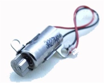
a)
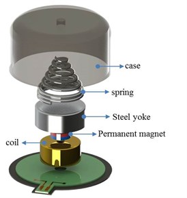
b)
2. Requirements and design
2.1. Structure of horizontally vibrating linear actuator
Fig. 2 shows schematic diagrams of the horizontal linear vibrating actuator. The actuator is composed of a movable part and a non-movable part. The movable part consists of a permanent magnet that provides a uniform magnetic field in the air gap, a steel yoke, a tungsten weight, and a housing. The tungsten weight increases the mass of the movable part and results in larger vibration. The movable part is supported and guided by mechanical springs.
Fig. 2Schematic diagram of horizontal linear vibrating actuator
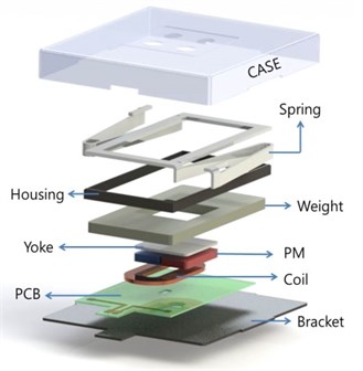
The non-movable part is the coil attached to the printed circuit board (PCB). When electric current is applied through the coil, the movable part vibrates due to magnetic force. The magnetic force, called the Lorentz force, is described by Eq. (1) [6]. represents the magnetic flux density in the airgap, is the input electric current, is the effective coil length, is the number of coil windings, and is the input frequency of the electric current. The sinusoidal electric current makes the movable part vibrate horizontally:
2.2. Performance requirements of vibrating actuator in a smart phone
Table 1 shows the performance requirements of the proposed horizontal linear vibrating actuator in smart phone as specified by smart phone manufacturer.
Table 1Performance requirements of horizontal linear vibrating actuator
Requirement | Unit | Values |
Natural frequency | Hz | 175 (+10 error) |
Vibration | G | 1.5 ~ 2 |
Product life | hr | 168 |
Thickness | mm | 2.8 ~ 3 |
2.3. Design procedure
2.3.1. Mathematical vibration model
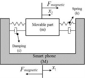
First, the mathematical vibration model was created in order to calculate the required magnetic force of the horizontal linear vibrating actuator. Fig. 3a shows a schematic diagram of a smart phone equipped with a horizontal linear vibrating actuator. The movable part is connected to the smart phone by mechanical springs. Its vibrating motion, created by a sinusoidal magnetic force, is transferred to the smart phone. The vibration was modeled as a semi-finite system, as shown in Fig. 3b [7]. The mass of the movable part of the vibrating actuator and the mass of the smart phone, including other all components, are expressed as and , respectively. The spring stiffness and structural damping of the guide spring are expressed as and , respectively. is 1.41 g and is 100 g according to the smart phone manufacturer. Table 2 shows the specifications used in the mathematical modeling. The governing equations of the system are given by Eq. (2) [8]:
Fig. 3a) Schematic diagram of smart phone equipped with a horizontal linear vibrating actuator, b) free body diagram of the horizontal linear vibrating actuator
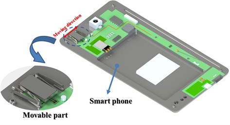
a)
b)
Table 2Specifications for mathematical modeling
Symbol | Unit | Parameter | Value |
Kg | Mass of smart phone | 0.1 | |
Kg | Mass of actuator | 0.0014 | |
Ns/m | Damping coefficient | 0.0143 | |
kN/m | Spring coefficient | 1.691 |
The initial displacements and velocities of the moving part linear actuator and smart phone were considered to be zero. Also, the motion was assumed to be harmonic as described by Eq. (3), and the mechanical natural frequencies of the system can be described by Eq. (4) [9]:
To solve the system, Eq. (2) can be written as Eq. (3), which can be summarized as follows:
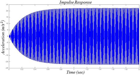
Here, and represent the displacement of the smart phone and one of the vibrating actuator movable parts, respectively. The acceleration of the smart phone and the movable part can be derived by multiplying and by , respectively [10]. The mechanical natural frequency of the vibrating actuator can be simplified as since in Eq. (4). The mechanical natural frequency must be equal to the electrical input frequency for resonance to occur, which will maximize the mechanical vibration. The stiffness k was calculated to be approximately 1700 N/m by considering the electrical input frequency to be approximately 175 Hz and the mass of the moving part () to be 1.41 g. In addition, the actual vibration was 20 % less than the value predicted by the mathematical vibration model due to the burn-in effect, which is also called the aging effect. Our target vibrating acceleration for the smart phone is 2.0 G. Accordingly, is calculated to achieve the vibration of approximately 2.2 G. To solve the mathematical model, a simulation using MATLAB® (Version R2013, Mathworks) was performed. Fig. 4 shows the vibration characteristic analysis of the mathematical model. The results show that 0.02 N of can accomplish approximately 2.2 G of vibration for the smart phone.
Fig. 4Vibration characteristic analysis of horizontal linear vibrating actuator using MATLAB
2.3.2. Design of the magnetic circuit
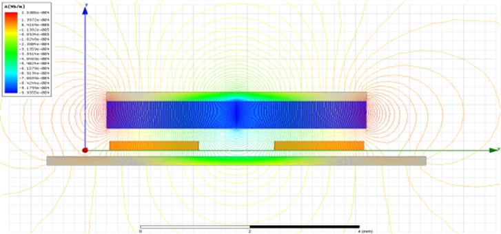
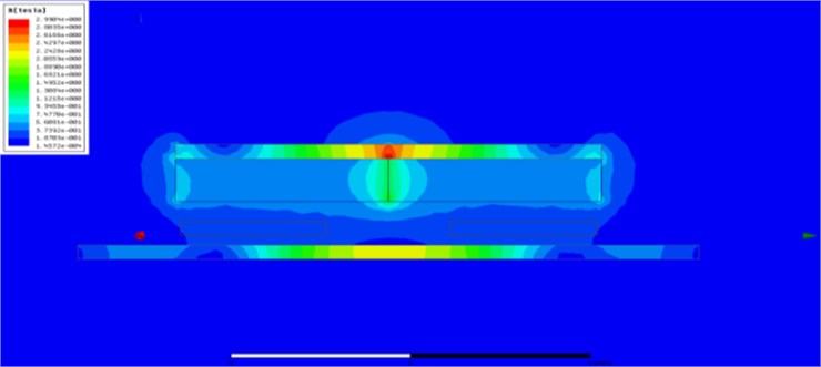
The design variables, such as , and , need to be determined to realize the value of calculated by mathematical modeling [11]. The is determined by the design of the steel yoke and permanent magnet. , and are determined by the design of the electromagnetic coil. The electric current is specified as approximately 0.08 A by the smart phone manufacturer. The number and shape of coil turns were determined to be 26 ohms for the coil resistance, based on the shape of the permanent magnet and steel yoke. The most important consideration in this design is that the thickness of actuator must be less than 2.5 mm. Finite element analysis was performed using the commercial electromagnetic analysis software Maxwell (Version 14, ANSYS) to design the magnetic circuit [12, 13]. A two-dimensional (2-D) finite element model was created using the magnetic material properties shown in Table 3. Fig. 5 a and b) show plots of the flux line distribution and magnetic field resulting from the FE analysis, respectively.
Table 3Materials of the permanent magnet, yoke, and coil
Component | Materials |
Magnet | NdFe35 |
Yoke | steel 1010 |
Coil | copper |
Fig. 5a) Flux line of horizontal linear-type motor, b) B-field of horizontal linear-type motor
a)
b)
2.3.3. Design of mechanical leaf spring
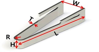
The mechanical leaf spring supports and guides the horizontal vibration of the movable part of the actuator. In addition, it transfers the vibration energy from the actuator to the smart phone. The mechanical leaf spring is under compressive and tensile cycling loading due to the vibration of the movable part. The design variables of the mechanical leaf spring are shown in Fig. 6 [14].
Fig. 6Design variables of the leaf spring (W – Width of spring, T – Thickness of spring, H – Height of spring, L – Length of spring, R – Radius of spring)
To design the mechanical leaf spring, a modal analysis and harmonic response analysis were performed using the commercial structural analysis program ANSYS Workbench (Version 14.5, ANSYS). The mechanical material properties for these analyses are given in Table 4 [15].
Table 4Material properties of the moving part
Component | Material | Density (g/cc) | Modulus of Elasticity (GPa) | Possion’s Ratio | Tensile strength, Yield (MPa) |
Leaf spring | sus304 | 8.00 | 193 – 200 | 0.29 | 215 |
Weight | tungsten | 19.3 | 400 | 0.28 | - |
Housing | sus304 | 8.00 | 193 – 200 | 0.29 | 215 |
Magnet | NdFe35 | 7.50 – 7.80 | 150 – 160 | - | - |
Steel yoke | steel 1010 | 7.84 – 7.87 | 200 – 205 | 0.29 | - |
2.3.3.1. Modal analysis
The mechanical leaf spring in the horizontally vibrating linear actuator was designed with a stiffness of 1700 N/m to achieve a resonance frequency of 175 Hz with a mass of 1.41 g (the movable part). In our finite element model of the mechanical leaf spring, 14,525 elements and 72,623 nodes were generated [16]. Figure 7 shows the 3-D meshed FE model.
Fig. 73-D model of the meshed movable part
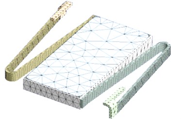
Material properties were assigned to the movable parts (the permanent magnet, steel yoke, tungsten weight, and leaf spring). The modal analysis was repeatedly performed until the first resonance frequency of the movable part to be 175 Hz in primary mode.
2.3.3.2. Harmonic response analysis
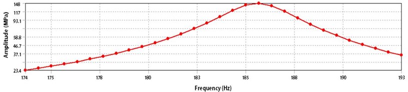
A harmonic response analysis was performed to confirm that the maximum stress near the folded area in the mechanical leaf spring is less than the yield stress at resonance. Figure 8 shows the results of the leaf spring harmonic response analysis [17]. The maximum stress generated at resonance is 148 MPa, which is less than the approximate yield stress of sus 304.
Fig. 8Harmonic response of horizontal linear vibrating actuator
2.3.4. Prototype
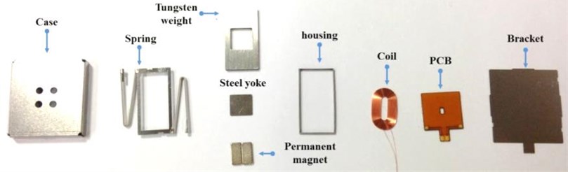
A prototype of the horizontally vibrating linear was manufactured. Fig. 9 shows each component.
Fig. 9Component of a horizontal linear vibrating actuator
The components were assembled using glue and laser welding [18]. Fig. 10 shows the laser welding set-up (MAX-300P, THM KOREA). A close-up of welding spot is shown by a laser shutter equipped with the camera. Fig. 11 shows the final manufactured prototype, with specifications of 16.5 mm width × 15 mm height × 2.5 mm thickness.
Fig. 10Laser welding machine set-up
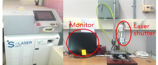
Fig. 11Horizontal linear vibrating actuator

3. Experiments and results
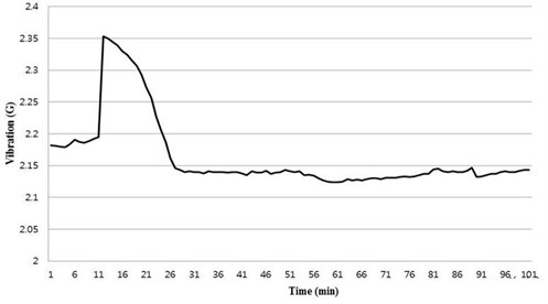
An experiment was performed to measure the vibration of a smart phone using the manufactured horizontal linear vibrating actuator prototype. A test zig of 100 g was built. The zig replaced the smart phone for the vibration measuring test [19]. Figs. 12 and 13 show the set-up and the procedure of experiment, respectively. The prototype of the horizontal linear vibrating actuator was installed in the slot of the test zig, and the acceleration sensor was attached to the left side of the zig. To confirm the resonance frequency, a vibration tester swept the signal with 160 to 190 Hz sine waves. Then, the horizontal linear vibrating actuator was energized, and the vibration of the zig was measured at the resonance frequency during continuous operation. Fig. 14 shows the results of the vibration measuring test [20]. The vibrating actuator generated a vibration of approximately 2.1 G after the burn-in phenomenon.
Fig. 12Experimental set-up
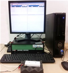
Fig. 13Experimental process for the horizontal linear vibrating actuator
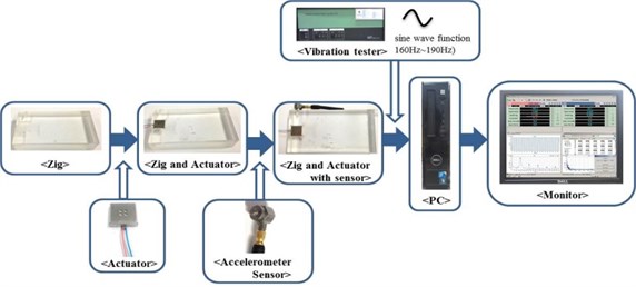
Fig. 14Experimental results for the horizontal linear vibrating actuator
4. Conclusions
In this study, a horizontally vibrating linear actuator to reduce the thickness of a smart phone was developed. The proposed actuator meets the performance specification required by smart phone manufacture. Its size is 16.5×15×2.5 mm (width × height × thickness). Its thickness decreased by at least 30 % compared to the vertically vibrating linear actuator, although it become broader. The proposed actuator's greater width is not a problem because recent smart phones with broad display panels have extra space in the width direction. In addition, the proposed actuator improves the vibration by more than 40 %.
References
-
Chung S.-U., Hwang G.-Y., Hwang S.-M. Development of Breshless and Sensorless Vibration Motor Used for Mobile Phone. IEEE Transactions on Magnetics, Vol. 38, Issue 5, 2002, p. 3000-3002.
-
Sang-Moon Hwang. Development of Solenoid-Type Vibrators Used for Mobile Phones. IEEE Transactions on Magnetics, Vol. 39, Issue 5, 2003, p. 3262-3264.
-
http://www.samsung.com/sec/galaxys4ltea/
-
M. Hiyane, Y. Inoue, M. Kurusu. Development of linear motion actuator. Fujitsu Scientific and Technical Journal, 1972, p. 59-92.
-
Jae- Hee Kim, Jin-Ho Kim. A horizontally vibration linear actuator for slimming of smart phone. Proceedings of the ICCESSE Conference (2011) December 21-23, Phuket, Thailand.
-
Hwang K.-I., Kim J.-H. Single-axis Flat Electro-Magnetic Actuator using Shorted Turn for Fast Initial Response. J. KMS, Vol. 19, Issue 6, 2009, p. 222-226.
-
Rao S. S. Mechanical vibration. Pearson Education International, 2004, p. 383-391.
-
Kim K.-H., Choi Y.-M., Nam B.-U., Lee M.-G. Dual Servo Stage Without Mechanical Coupling for Process of Manufacture and Inspection of Flat Panel Displays Via Modular Design Approach. Int. J. Precis. Eng. Manuf., Vol. 13, Issue 3, 2012, p. 407-412.
-
Rao S. S. Mechanical vibration. Pearson Education International, 2004, p. 409-422.
-
Suk-Min Yoon, Jae-Hee Kim, Jin-Ho Kim. Mathematical Modeling and Analysis of Vibration Characteristics of Smart-phone. International Journal of Precision Engineering and Manufacturing, Vol. 14, Issue 3, 2013, p. 505-508.
-
Hwang K.-I., Kim J.-H. Single-axis Flat Electro-Magnetic Actuator using Shorted Turn for Fast Initial Response. J. KMS, Vol. 19, Issue 6, 2009, p. 222-226.
-
Coulomb J. A methodology for the determination of global electromechanical quantities from a finite element analysis and its application to the evaluation of magnetic forces, torques and stiffness. IEEE Transactions on Magnetics, Vol. 19, Issue 6, 1983, p. 2514-2519.
-
Slama Afef, et al. Electric railgun 3D modeling: computation of eddy currents and Lorentz force. IEEE Transactions on Magnetics, Vol. 37, Issue 1, 2001, p. 139-142.
-
Ki-Bum Lee, Jin-Ho Kim. Design of leaf spring with high fatigue life applied to horizontal linear vibrating actuator. Journal of the Korea Academia-Industrial cooperation Society, Vol. 13, Issue 12, p. 5684-5688.
-
http://www.matweb.com/index.aspx
-
Kang Y., et al. Modal analyses and experiments for engine crankshafts. Journal of sound and vibration, Vol. 214, Issue 3, 1998, p. 413-430.
-
Wu Zhijun, et al. Modal and Harmonic Reponse Analysis and Evaluation of Machine Tools. 2010 International Conference on Digital Manufacturing and Automation (ICDMA), Vol. 1, 2010.
-
Duley Walter W. Laser welding. New York, Wiley, 1999.
-
McConnell, Kenneth G., Paulo Sérgio Varoto. Vibration testing: theory and practice. Seoul, John Wiley & Sons, 1995.
-
Candinas Reto, et al. Vibration, acceleration, gravitation, and movement: activity controlled rate adaptive pacing during treadmill exercise testing and daily life activities. Pacing and clinical electrophysiology, Vol. 20, Issue 7, 1997, p. 1777-1786.
About this article
