Abstract
The article presents the authors’ own studies on the application of polymer materials with different physical and chemical properties for vibro-insulation of lifting appliances. The studies were performed on a static test stand, which was made as part of works on the examined polymers, as well as on a dynamic test stand. We analyzed the effect of various polymer materials upon the phenomenon of susceptibility and possibility of returning to primary shape after the load disappears. We determined susceptibility characteristics for examined polyurethane materials. Study results are important from the point of view of improving the comfort and operation of lifting appliances.
1. Introduction
The carrying subsystems in hydraulic lifts are led in specially formed guides. The carrying frame of a lift is carried on roller-slide guides (pilots). The load , presented in Figure 1, constitutes a uniform load of the frame structure, this way causing uniform loading of rollers in the guides. The main operation problem is the deformation of rollers during longer period of the appliance’s inactivity, which, consequently, decreases riding comfort and increases failure frequency.
Fig. 1Roller guide load scheme: Q – frame lifting capacity, F – reactive component [1]
![Roller guide load scheme: Q – frame lifting capacity, F – reactive component [1]](https://static-01.extrica.com/articles/14509/14509-img1.jpg)
This article presents the results of studies on roller deformation depending on the applied polyurethane material, when the rollers undergo long-term static and dynamic load. We examined the radial deformation of the cylindrical surface of a guide roller. Three kinds of polyurethanes were studied, marked as BROWN, GREEN and WHITE. Unfortunately, because of the secret of polyurethane production, the manufacturer made a reservation against revealing any parameters of examined materials whatsoever.
2. Research object
The studies were performed on the rollers of a roller-slide guide. Roller is the main element, which leads the carrying frame of a hydraulic lift on guides. The structure of a roller is shown in Figure 2.
During operation the guide is loaded in accordance with Figure 1. We examined rollers working in the appliance with the load of 10 kN (1000 kg). Therefore, the load falling on one roller was determined on the level of 3.50 kN (350 kg) [2].
Fig. 2Polyurethane roller structure: 1 – polyurethane band, 2 – internal ring, 3 – bearing mountings [3]
![Polyurethane roller structure: 1 – polyurethane band, 2 – internal ring, 3 – bearing mountings [3]](https://static-01.extrica.com/articles/14509/14509-img2.jpg)
During work the guide is continuously exposed to the activity of forces resulting from frame loading. Rollers, moving on the guides, affected by the load, continuously deform the polyurethane material of the roller band. A long term outage (shut down) of the appliance, usually lasting about 5 hours, is a more unfavorable situation. Thus, the surface of the roller is statistically loaded. A roller, deformed like this and set in motion, does not operate properly, this way disturbing the safety and comfort of work. Therefore we tested rollers covered with three different elastomers, especially considering the possibility of returning their primary shape after unloading [4, 5].
3. Static tests
Tests were carried out on the test stand, the scheme of which was shown in Figure 3. This method involved deforming the roller (8) in the press built by the authors, with the use of a screw (3). The press built by us consisted of the lower and upper frame (1) and (2), which was moved on two round-section guides (6). In the upper frame two slide bearings were installed (7). The upper frame was pressed against the study object by means of a screw (3) of the stroke of 1 mm, which facilitated evoking a particular prestrain quantity through easy selection of screw revolutions number. The screw had a hollow opening, so that the pusher (4), could raise the tip of dial indicator (7), measuring the roller strain. All samples, one after another, were loaded by a screw with 5 coils of thread pitch, and then the screw was released. The rollers automatically returned to their initial shapes. Change of roller shape was registered by the deformation sensor (4). Change of indication in time was registered through a series of photographs of dial indicator taken automatically.
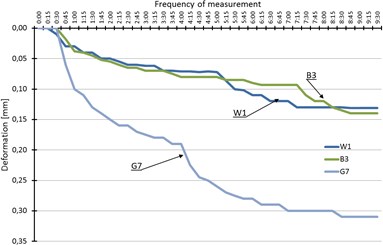
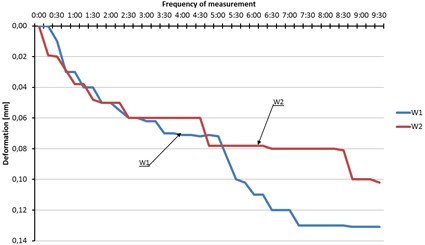
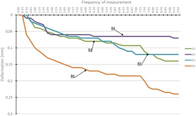
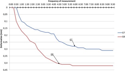
In the graphs 4(a) to 4(d) the obtained results were juxtaposed, which was related to the return of polyurethane coating to its primary shape. The results were registered every 15 minutes, until the ultimate cylindrical shape was obtained.
Fig. 3Test stand: 1 – Lower frame; 2 – Upper frame; 3 – Press bolt; 4 – Manometer pusher; 5 – Dial indicator; 6 – Guide; 7 – Slide bearing; 8 – Roller with a polyurethane band
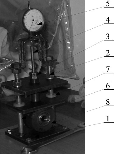
Fig. 4Results concerning the course of particular rollers’ return to their initial shapes after radial deformation of 5 mm, evoked within 9.5 h: W1, W2 – rollers white, B3, B4, B5, B6 – rollers brown, G7, G8 – rollers green
(a)
(b)
(c)
(d)
4. Dynamic tests
A testing machine was used for dynamic tests. A prism matrix was mounted on the machine, where the examined rollers were placed one after another. A flat stamp was pressed against the roll, causing deformation similar to real strain of the rollers on the guides. To perform measurements it was assumed that load cycles will be smoothly increased up to the boundary value of roller load, determined by its structure (3500 N).
Before performing the dynamic tests to check the applied polyurethanes, measurements of hardness were taken on the surfaces that underwent dynamic tests.
Hardness was measured with the use of OMAG hardness tester. In Table 1 data were presented, which were obtained by measurements as a mean of 5 hardness measurements performed one after another on the surface of a cylindrical roller. The hardness tester was shown in Figure 5.
Table 1Mean hardness of particular rollers
Roller number | Shore hardness scale A |
W1 (White) | 95 |
W2 (White) | 96 |
B3 (Brown) | 94 |
B4 (Brown) | 94 |
B5 (Brown) | 94 |
B6 (Brown) | 100 |
G7 (Green) | 95 |
G8 (Green) | 95 |
Fig. 5Scheme of hardness measurement stand (with the use of Shore’s method A)
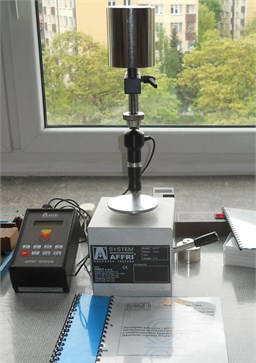
Fig. 6Hardness graph for particular rollers
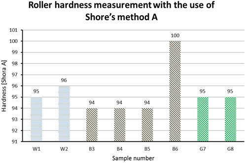
Hardness graph worked out on the basis of the data from Table 1.
The graph above (Fig. 6) shows that only roller B6 significantly differed in hardness from the remaining rollers. This is caused by the fact that the material used to manufacture the roller band was exposed to solar radiation much longer than the remaining rollers. The characteristic feature of the applied polyurethane band is that the exposure to rays of sunshine causes the band surface to harden. In reality the lift appliances work in darkened places, such as lift shaft, which minimizes the access of natural light.
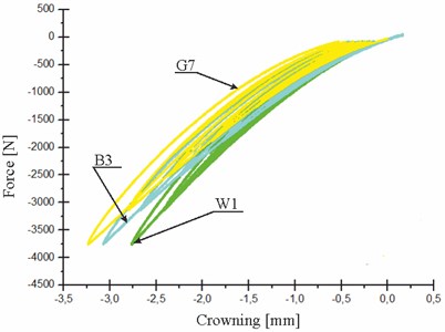
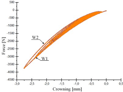
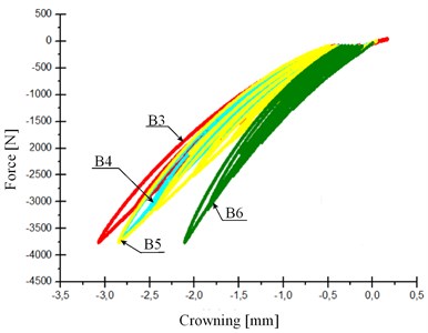
The figures below (Figs. 7(a)-(c)) show graphs of roller susceptibility in the function of deforming force, in the conditions of cyclic loading. During the test the cyclic increase of the force magnitude up to 3500 N was assumed and each cycle lasted 2.5 hours. The duration of a single cycle was determined on the basis of experimental roller deformation during loading test. The experiment time was selected in such a way as to prevent the polyurethane from straining too fast, which would cause fractures of the surface layer.
Fig. 7Comparing susceptibility of rollers: a) types: WHITE – BROWN – GREEN; b) type: WHITE; c) type: BROWN
(a)
(b)
(c)
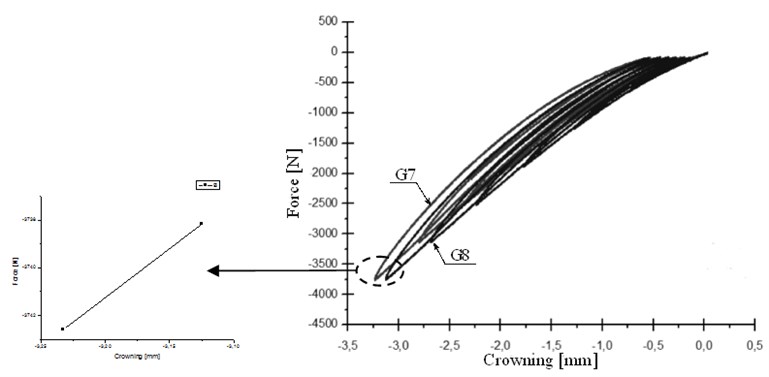
Fig. 8Susceptibility graphs for GREEN-type rollers with the shift of susceptibility characterization
5. Summary and conclusions
In the roller guides the time of idle work causes durable deformations of the roller cylindrical surfaces [6]. Usually such deformation is accompanied by decreased comfort of appliance work, as well as increased failure frequency. At such a durable deformation the lift needs a lot of time for the rollers to return to their primary shapes. In this article we decided to check what type of polyurethane band had better properties for fast return to primary shape in consequence of static and dynamic deformations. For that purpose a research method was used, involving static and dynamic loading of particular rollers on a manual press built for performing tests, as well as on a testing machine.
On the basis of the conducted studies and tests it was found that:
• The applied GREEN type polyurethane undergoes deformation to a greater extent (is more susceptible to deformation), than the two remaining polyurethanes – type BROWN and WHITE despite the same hardness of material, which is confirmed by both testing methods.
• Measurements of WHITE-type polyurethane susceptibility reveal the most repeatable susceptibility of all the three tested types, though in the static method the rollers showed different aptness to returning to their primary shape.
• Difference in hardness of the same type of polyurethane may result from the differences caused by the material structure or exposure to natural light. Changes in hardness of the examined polyurethanes are shown in Fig. 6.
• Comparing the deflection parameter in static assay and in hardness measurement shows that the material, which is most resistant to static deformations, is WHITE type material, whereas the most susceptible is GREEN-type material, which is shown in Figures 4(a) to 4(d).
• The shapes of obtained graphs 7(a-c) and 8 result from the changing volume of roller material in the effect of changing load. Cylindrical shape, at radial compression demonstrates progressively increasing rigidity. At the initial stage a straight line can be observed that changes its shape into a curved ellipse with the increase of deformed volume.
• As it was shown in figures 4(a) to 4(d) the ranges of durable deflections of rollers in static tests are as follows:
– For GREEN-type rollers: from 0.3 to 0.42 mm,
– For BROWN-type rollers: from 0.075 to 0.25 mm,
– For WHITE-type rollers: from 0.1 to 0.15 mm.
Finally, it has to be emphasized that the choice of material for guide rollers is crucial for proper lift exploitation. Applying too soft or too hard material for guide rollers would cause decreased riding comfort in the lift car or increased failure frequency in some elements of the appliance. Furthermore, the authors’ own studies confirm that the most appropriate material for roller coating is BROWN-type polyurethane. This is also confirmed by materials presented on websites [1] of roller manufacturers, as well as by the literature data [6-11].
References
-
Documentation of H13-type hydraulic lift manufactured by Lift Service S. A.
-
Lonkwic P. Disk springs in passenger lifts. Technical Inspection, Issue 4, 2012.
-
Technical-movement documentation of the frame RH4 manufactured by Lift Service S. A.
-
Leng Jinsong, et al. Synergic effect of carbon black and short carbon fiber on shape memory polymer actuation by electricity. Journal of Applied Physics, 2008.
-
Lonkwic P. Modernization of already existing lifts. Construction Engineering, Issue 12, 2011.
-
Shanmugasundaram O. L. Shape memory polymers and their applications. The Indian Textile Journal, 2009.
-
Brennan M. Suite of shape-memory polymers. Chemical and Engineering News, Vol. 79, 2001.
-
Havens E. Light-activated shape memory polymers and associated applications. Proc. SPIE5762, 2005.
-
Lendlein A., Kelch S. Shape-memory polymers. Angew. Chem. Int., 2002.
-
Toensmeier P. A. Shape memory polymers reshape product design. Plastics Engineering, Issue 2, 2009.
-
Tuleja J., Chmiel J. Polymer materials identification and research. Marine Academy in Szczecin, 2008.
About this article
