Abstract
In the article the results of studying a vibration exciter for vibration machining of the surface of the parts with a pneumatic vibratory drive, which showed its high efficiency when used in highly explosive and associated with fire risk productions, as well as for various technological processes of inertia machining parts based on beryllium oxide, are presented. As a result of the carried out analytical studies of an installation with a pneumatic vibratory drive, a mathematical model of vibration machining process dynamics was determined.The adequacy of the mathematical model of the compressed air flow effect on the roller in the pneumatic grinding set, as well as the roller mass effect on the oscillation amplitude was proved experimentally.The oscillation amplitude dependencies on pressure and the feeding nozzle diameter, when vibration process technology (vibration grinding, vibration polishing and others) of machining of parts is realized, are presented.
1. Introduction
The development of principally new efficient technologies, highly productive equipment and tools which are competitive at the world market, is one of the main tasks of present day machine building. At the enterprise JSC “Ust-Kamenogorsk Condenser Plant” a lot of manufactured small component parts (such as bases, paddings, holders for discrete units of the type of diodes, transistors, solid-state circuits, microchips and others) are subjected to abrasive machining which has a number of drawbacks, namely: low productivity and great dust emission in the process of manufacturing.
A lot of tools used in the process of machining are made based on beryllium oxide which is toxic in the powdered state (the first class of danger). Besides, in the process of machining of parts it is needed to perform the dust suction immediately from the zones of machining, and the workrooms dust content increases the risk of their fire and explosion hazard. To do these operations at the enterprises mainly the equipment with electric drive is used, the use of which in explosive and fire risky productions is dangerous and is not recommended. The equipment with pneumatic drive having no such drawback is not widely spread [1].
Thus the studies in the direction of increasing productivity, production and ecological safety in manufacturing of products based on beryllium oxide due to developing multi-function technological equipment with a pneumatic vibratory drive for inertia vibroabrasive machining are urgent.
2. Object of the study
A vibration exciter for the vibroabrasive machining of surfaces of parts with a pneumatic vibratory drive was developed after studying the process of interaction of compressed air with the roller freely located in the turbulence chamber. The rolling action across the inner wall of the turbulence chamber takes place due to irregularity of the air pressure distribution on its surface. Technological possibilities of using such type of device for the surface machining include the following succession of the process: placing paste-like coverings, their smoothing or cutting after polymerization and the following abrasive machining. The complicated planetary motion of the tool ensures high quality machining, there is no need to fix it mechanically, it eliminates the time consumption for sticking and re-sticking of the products.
The analysis of the existing vibration drives revealed their following drawbacks [2, 3, 4]: low ecological compatibility and quick wear of the working elements due to transverse oscillations and due to a lot of mechanical force ties.
Fig. 1A set for vibroabrasive machining: 1 – base; 2 – movable frame; 3 – resilient supports; 4 – inner cylindrical surface of vibroblock case; 5 – inlet opening; 6 – located outlet openings; 7 – outer tubing; 8 – inner tubing; 9 – filtering element; 10 – unbalanced mass
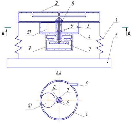
In the work a more efficient and simple pneumatic vibratory drive for a vibration exciter is suggested (an application for issuance of an Innovation Patent No. 2010/042.2 – A set for vibroabrasive machining). Besides, when designing and developing the equipment for vibroabrasive machining based on the Technological Park “Altai”, new engineering solutions patented in the Republic of Kazakhstan (Nos. 18692, 18693, 19161) were used. The main purpose of the suggested equipment is increasing the device wear resistance and ecological safety. The technical result of using the suggested useful models consists in removing and filtering the waste products formed in the process of machining of parts, using the compressed air flow as a force kinematic tie and using the exhausted gas for operating a built-in ejector and a centrifugal filter. The set for vibroabrasive machining operates as follows (Figure 1): unbalanced mass 10 is moved by the compressed air flow entering through tangentially located inlet opening 5, rolling the inner cylindrical surface of vibroblock case 4, forms oscillations that, respectively, cause the oscillations of movable frame 2 on resilient supports 3 mounted on the base 1. The exhausted gas comes out through tangentially located outlet openings 6 in the outer tubing 8 and the inner cone groove of the outer tubing 7, thus forming an ejector spray head. It forms a zone of evacuation in front of inner tubing end 8 that is on the other side connected with the outer surface of the movable frame, where there the vibroabrasive machining of parts and removal of the machining waste products takes place. The exhausted gas mixed with the machining waste products enters filtering element 9.
The defining parameters of the pneumatic vibration exciter for inertia vibroabrasive machining of surfaces of a part are the amplitude and frequency of vibration of the abrasive tool fixed in the vibrating hopper and the efficiency of the collection of powdered waste products.
Pneumatic vibratory drives realize the effect of interaction of compressed air flow with the unfixed object in the form of a solid of rotation located in the closed cylindrical chamber.
Characteristics of the oscillation process include the kinematic-geometrical parameters of the vibratory drive case, the unfixed object in the cylindrical chamber, characteristics of elastic elements (springs), the compressed air flow speed and rate.
Due to the flexibility of the changing of the process characteristics there appears the possibility without significant costs to change the oscillations amplitude and frequency of the tool fixed in the vibrating hopper.
In order to carry out the studies an experimental vibration exciter was developed (Fig. 1) and a methodology of experimental studies of the pneumatic vibration exciter for various technological processes of inertia machining parts based on beryllium oxide was also developed.
3. Experimental studies and modeling of the process
An experimental vibration exciter for studying the process of vibroabrasive machining presented in Fig. 2 consists [5, 6, 7] of case 1, on which there is a loaded spring with the possibility of horizontal motion, vibrating hopper 2 with the abrasive tool fixed on it. In alignment with the vibrating hopper, on its bottom surface there is fixed vibratory drive 3 connected with compressed air source 4. On the abrasive tool there are freely located parts to be machined 5. On top the vibrating hopper is covered with transparent shield 6. The vibratory drive consists of free roller 7, rolling across the inner surface of cylindrical case 8, input 9 and output 10 nozzles. In the lower part of the vibratory drive recording element 11 is fixed.
Fig. 2Diagram of experimental pneumatic vibration exciter for studying the process of inertia vibroabrasive machining: 1 – case; 2 - vibrating hopper; 3 – vibratory drive; 4 – compressed air source; 5 – freely located parts to be machined; 6 – transparent shield; 7 – free roller; 8 – cylindrical case; 9 – input nozzles; 10 – output nozzles; 11 – recording element
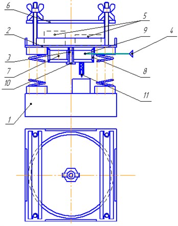
The experimental vibration exciter operates as follows. When compressed air is fed to the vibratory drive, the latter actuates the oscillation motion of the vibrating hopper with amplitude and frequency . With a corresponding speed and amplitude of the oscillating process the machined parts under the action of their own inertia remain relatively stationary and due to the relative motion of the abrasive tool metal removal from the machined surface takes place.
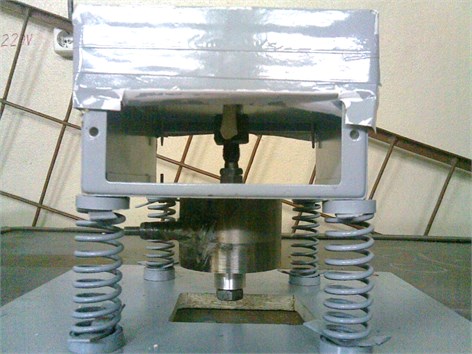
In Fig. 3 a general view of the experimental vibration exciter for studying the process of inertia vibroabrasive machining is presented.
The mathematical model of the pneumatic vibration exciter consists of two models: a model describing the compressed air effect on the roller in the pneumatic drive of the vibration exciter, and a model of the interaction of the abrasive tool fixed in the pneumatic vibration exciter vibrating hopper (in our case grinding paper) with the machined part.
In this work the first model is mainly considered, nonlinear dependencies relating to the process of vibroabrasive machining itself are considered in the works of other authors [8, 9].
Fig. 3Experimental vibration exciter for studying the process of inertia vibroabrasive machining
In order to determine one of the main parameters of the oscillation process, i.e. frequency (), from the condition of the balance of the forces acting on the object in the cylindrical chamber of the pneumatic drive, the dependence of the tool oscillation frequency on the changes of the main kinematic-geometrical parameters of the vibration exciter was analytically derived:
where is head resistance factor; is air rate coefficient; is compressed air feeding pressure, МPа; is the feeding nozzle cross-section, mm2; is acceleration of gravity, m/s2; is the roller mass, g; is the factor of sliding friction between the roller end and the case cap; is the roller radius, mm; is the factor of rolling friction between the case and the cylindrical surface of the roller; is inner radius of the vibratory drive case, mm.
Then in order to determine the next main parameter of the oscillating process of the pneumatic vibration exciter, i.e. amplitude (), from the balance of the forces acting on the vibrating hopper the mathematical dependence of the tool oscillation amplitude on the kinematic-geometrical parameters of the vibration exciter was analytically derived:
where is the roller mass, g; is the angular speed of the roller motion, rad/s; is the radius of the roller axe motion, mm; is elastic coefficient with four springs shift, N/mm.
In order to check the analytical dependencies, a decision to carry out the complete factorial experiment was made.
The main criteria of workability of the pneumatic vibration exciter designed for realizing the technology of vibroabrasive machining of part surfaces are the parameters of the oscillation process, i.e. amplitude () and frequency () of the case oscillations and under-pressure in the ejector central channel. Increasing of oscillation amplitude () and frequency () lead to the growth of machining productivity. Starting from this, the optimization parameters are taken as the vibratory drive amplitude () and oscillation frequency ():
where is the roller mass, g; is the roller radius, mm; is the tangential feeding nozzle radius, mm; is the air pressure fed by the tangential feeding nozzle in the chamber, Pa; is the atmospheric opening radius, mm; is the case mass, g; is the case inner radius, mm; is the machined part mass, g.
In order to solve the problem of optimization, it is necessary to weed out the least important and to select the most important kinematic-geometrical parameters of the vibration exciter that effect immediately the tool oscillation amplitude () and frequency (), for realizing various technological vibration processes. Besides at the stage of the experiment planning by the method of statistical analysis of expert estimates the main kinematic-geometrical parameters were selected. On the analysis of the ranging results an a priori ranges diagram was built, from which the most significant parameters were selected: , the input nozzle radius (), , pressure () and , the roller mass ().
The remaining factors were established as follows: total hardness of the 4 springs 7 N/mm; the roller radius 30 mm; the vibratory drive case radius 80 mm; rolling friction coefficient 0.01; sliding friction coefficient 0.01; head resistance coefficient 0.8; compressed air rate factor 0.9. These parameters were selected starting from the expert evaluations.
The feeding pressure is established by the manometer using pressure regulators up to necessary values. The diameters of the input and output nozzles are changed using replaceable brasses. The rollers are made of different mass. In order to minimize eventual errors the work was done at the same time of day and by the same researcher.
There were three repeated experiments.
The methodology of carrying out the experiment and the interpreting of the results were carried out in accordance with works [10, 11].
An experiment of 23 type was carried out, where the number of factors was 3, the number of levels 2, the number of experiments 8, the number of repeated experiments 3.
The degree of freedom () is calculated by the formula:
Then the tabulated value of the correlation coefficient will be equal to 0.811. Since in our case there is , we make a conclusion that the derived empiric dependence reflects the vibration exciter processes adequately.
The regression equation for amplitude () will have the form:
By the calculated regression equation a graph presented in Fig. 4 was built.
The regression equation for oscillation frequency () has the form:
By the calculated regression equation the graphs shown in Fig. 5 were built.
By the obtained arrays the correlation coefficients for amplitude () that is equal to 0.96 and for frequency () – 0.98 were calculated.
Thus the derived analytical dependencies of amplitude () and oscillation frequency () on the vibration exciter’s kinematic-geometrical parameters correspond to the real experimental specimen, and maximum deviation of the results obtained analytically and experimentally is not more than 12 %.
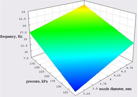
Fig. 4Graph of oscillation amplitude dependence on pressure and the feeding nozzle diameter according to the calculated formula of the regression equation
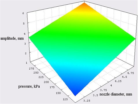
Fig. 5Graph of oscillation frequency dependence on pressure and the feeding nozzle diameter according to the calculated formula of the regression equation
Parallel to the analytically derived formulae of the regression equations for amplitude () and frequency () of oscillations of the vibration exciter in Fig. 6, 7 and 8 the comparison of the main parameters obtained by the derived analytical and experimental dependencies (with the same parameters as in the carried out experiments) is presented.
Fig. 6Comparison of the main parameters of oscillations by the derived analytical and experimental dependencies (variable parameter is the fed pressure, P)
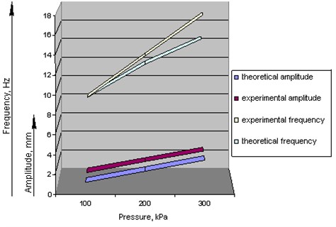
Fig. 7Comparison of the main parameters of oscillations by the derived analytical and experimental dependencies (variable parameter is the input nozzle radius, rc)
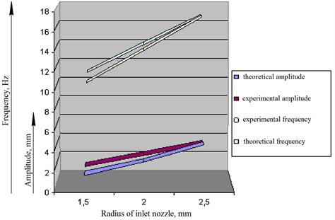
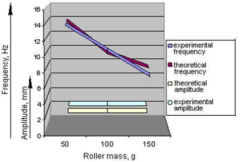
Fig. 8Comparison of the main parameters of oscillations by the derived analytical and experimental dependencies (variable parameter is the roller mass, mp)
Let’s compare the main oscillation parameters (amplitude and frequency ) obtained by the derived analytical dependencies and experimentally obtained regression equations depending on the meaningful kinematic-geometrical parameters of the vibration exciter (input nozzle radius is , pressure is and roller mass is ) (Table 1).
Table 1Main parameters of oscillations by the derived analytical and theoretical dependencies and experimentally obtained regression equations depending on the three parameters of the vibration exciter
Input nozzle radius, mm | 1.5 | 1.5 | 1.5 | 1.5 | 2 | 2.5 | 1.5 | 1.5 | |
Pressure, kPa | 100 | 200 | 300 | 150 | 150 | 150 | 150 | 150 | |
Roller mass, g | 100 | 100 | 100 | 100 | 100 | 100 | 50 | 100 | |
Experimental amplitude, mm | 1.4 | 2.5 | 3.6 | 2 | 3.1 | 4.2 | 2 | 2 | |
Experimental frequency, Hz | 8.6 | 12.9 | 17.2 | 10.7 | 13.7 | 16.7 | 14 | 10.7 | |
Analytically derived amplitude (theoretical), mm | 1 | 2.2 | 3.3 | 1.66 | 2.9 | 4.6 | 1.6 | 1.6 | |
Analytically derived frequency (theoretical), Hz | 8.1 | 11.6 | 14.3 | 10 | 13.4 | 16.8 | 14.3 | 10 | |
Angular speed (theoretical), rad/s | 51.4 | 73.2 | 89.8 | 63.2 | 84.6 | 106 | 89.8 | 63.2 | |
4. Analysis of the obtained data
Let’s explain the physical meaning of the regression equations obtained. The obtained ratio shows the interconnection between the vibratory drive amplitude and oscillation frequency with such factors as the input nozzle radius , pressure , the roller mass .
The second optimization parameter, i.e. frequency , depends proportionally on the mentioned factors as is indicated by the linear dependencies. With increasing the first two factors ( and ) frequency () is to increase and with increasing the third factor () it is to decrease. Pressure has the greatest effect, the pair interactions of all the factors turned out to be negligible.
The first optimization parameter, i.e. amplitude (), depends proportionally on the first two factors ( and ). When these factors are increased, then the amplitude also increases. Pressure has the greatest effect, the pair interactions of all the factors appeared to be negligible. The third parameter, i.e. the roller mass (), its effect turned out to be negligible, as the pair interactions of all the factors.
Explanation of this phenomenon is to be found in the fact that the centrifugal force is approximately the same at any roller mass (with increasing the roller mass () the angular speed reduces, and with decreasing the roller mass the angular speed grows, and with their product the force changes negligibly).
The maximum value of the amplitude was reached with the input nozzle diameter 5 mm, pressure 300 kPa, roller mass 150 g and was equal to 6.3 mm.
The maximum value of the frequency was reached with the input nozzle diameter 5 mm, pressure 300 kPa, roller mass 50 g and was equal to 28 Hz.
The results of the analytical and experimental studies were implemented at LLP “Proba” (Limited Liability Partnership “Proba”) as recommendations for designing and calculating the equipment with a pneumatic vibratory drive.
5. Conclusions
1. A mathematical model of a pneumatic vibratory drive was developed in the form of dynamics differential equation.
2. The analytical dependencies of the tool oscillation amplitude and frequency on the kinematic-geometrical parameters of the vibration exciter were obtained, as well as the main dynamic conditions under which the vibratory process technology of machining of parts was realized (vibration grinding, vibration polishing, etc.).
3. It was proved that the suggested kind of machining is possible only with exceeding the machined part inertia force over the friction force between the machined part surfaces and the vibration exciter rubbing surface.
4. It was established experimentally that the developed mathematical model of compressed air flow effect on the roller in the pneumatic grinding set is adequate to that of the real set.
5. In the process of the complete factorial experiment it was established that the roller mass effect on the oscillation amplitude appeared to be negligible and the maximal discrepancy between the analytical and experimental results was no more than 12 %.
6. An original version of a pneumatic drive for a vibration exciter was developed providing, due to the compressed air feed, the tool rotational oscillation movement, ejection of waste products and their filtration.
References
-
Saltykov V. A., Semyonov V. P., Syomin V. G. Machines and Equipment of Machine-Building Enterprises. SPb.: BHV, Petersburg, 2011, 288 p.
-
Tongue Benson Principles of Vibration. Oxford, Oxford University Press, 2001, 367 p.
-
Inman Daniel J. Engineering Vibration. Prentice Hall, 2001, 295 p.
-
Thompson W. T. Theory of Vibrations. Nelson Thornes Ltd. 1996, 295 p.
-
Goltsev A. G., Kurmangaliyev T. B., Timoshin V. I. RK Patent 18692. IPC В07В 1/281. Vibration Exciter, 15.08.2007, Bul. No. 8.
-
Goltsev A. G., Kurmangaliyev T. B., Timoshin V. I. RK Patent 18693. IPC В07В 1/28. Vibration Exciter, 15.08.2007, Bul. No. 8.
-
Goltsev A. G., Kurmangaliyev T. B., Timoshin V. I. RK Patent 19161 РK. IPC В07В 1/28. Vibration Exciter, 14.03.2008, Bul. No. 3.
-
Prokopets A. A. Analyzing mechanisms of abrasive working medium wear in vibroabrasive machining. DSTU Bull., Vol. 10, No. 1(44), 2010.
-
Shevtsov S. N. Computer Modeling of Granulated Media Dynamics in Vibration Technological Machines. HS SKNC, Rostov/Don, 2001, 194 p.
-
Lavrov V. V., Spirin N. A. Methods of Planning and Processing Engineering Experiment Results. GOU VPO USTU-UPI, Yekaterinburg, 2004, 257 p.
-
Zubarev Yu. M., Nechayev K. N., Katenev V. I., Shishov G. А. Using Methods of Theory of Planning Multifactor Experiments in Machine Building Technology. SPb.: PIMmash, 2000, 130 p.
About this article
