Abstract
Vibration torque are existence obviously during operation of stepping motor, it is a periodic structure vibration problem. In this paper, the motion model of motor is deduced and is compared with the motion mathematic model of pendulum; then actual vibration torque testing of stepper motor is executed through a self made vibration torque sensor, including single-step operation, low frequency continuous operation, low frequency lost step oscillation and continuous operation, the experimental results show that the stepping motor vibration torque of single three shot operation is more bigger than the six shot, and obvious reply oscillation existence in two operations; sharp vibration torque is generated on low frequency lost step oscillation; the vibration torque of single step operation is greater than the continuous operation, and vibration torque is decreasing with the frequency increasing; last, the generation of these experimental phenomena are analyzed, and the relationship between the stepper motor vibration torque peak value and frequency of the normal continuous operation are found, it can provide a certain reference for controller or control algorithm designation of stepper motor.
1. Introduction
Stepper motor is a kind of micro motor which convert electric pulse into angular displacement or line displacement, its angular displacement is proportional to the number of pulses and has no relation to voltage or out condition in the load capacity scope, and it is used mainly as the implementation components in the open-loop control system, such as printers, NC machine tools, robots and other places where needs to be located accurately [1-4]. But the stepper motor exist obvious oscillation in operation process, it is manifested as the motor speed fluctuation (resonance or jitter), even cause displacement and vibration on extremely cases, and it is the main factors for step motor speed stability, because the torque angle characteristic of stepper motor is nearly sine function, and the magnetic field of the stator turning as jumping.
In recent years, the torque fluctuation or speed fluctuation of stepper motor is studied by some experts and scholars. According to the starting out-of-step and mechanical impact of stroke termination effectively on linear stepper motor, a control system based on DSP2407 was proposed by HongMin Zheng [5]. A new type of stepper motor controller is designed by Bo Qu [6], the performance of the microprocessor STM32F103RBT6 and the driving principle of stepper motor driver chip L6208 are analysed. To solve the problems existed in traditional stepper speed control algorithm, a novel algorithm based on space control instead of time control was introduced by Baoshan You [7]. The measurement of the stepper motor rotation stability by optical encoder and its evaluation criterion were presented by Pan Jin Yu [8], it is based on the analysis of effect for rotation performance of stepping motor in low-speed scan. Based on repetitive control of time-varying periodic signals, a new method of restraining toque ripple for 5-phase hybrid stepping motor system is proposed [9], and the principle of torque ripple is analyzed. By analyzing two-phase hybrid type stepping motor mechanical structure, a variety of factors impacting on the starting process of stepping motor were deduced theoretically, and a set of measurement system of stepping motor performance based on the photoelectric sensor was constructed [10].
In this paper, a self-made vibration torque sensor is used for measuring the stepper motor torque fluctuation [11]. The sensor is able to detect instantaneous torque fluctuation relative to the grating and photoelectric encoder method in the reference. Last, the experimental results are analyzed and studied, it can provide a certain reference for controller or algorithm designation of stepping motor.
2. Stepper motor motion model
The reluctance torque of reactive step motor produced by different reluctance of teeth, and the static torque is refer to a electromagnetic torque, which generated on conditions that a windings going through DC current, the expression of stepping motor static electromagnetic torque can be induced through the principle of energy balance relationship, which exist in energy conversion between mechanical and electrical. When phase windings of stepper motor going through DC current :
In Eq. (1), is control voltage applied in phase windings; , are resistance and inductance of phase windings respectively; the input energy of windings in is:
Inductance is magnetic chain number produced by unit current, then , so we can receive:
It can indicated that the energy of phase windings one part is converted into heat energy , it is consumption of the windings resistance , the other part is converted into electromagnetic energy stored in the magnetic field of phase windings, it is the source of torque to do foreign power. When the response electromagnetic torque drive the rotor turned the deflection angle , the stepping motor output mechanical energy which is converted from the storage magnetic field energy, so according to the energy balance relationship, then:
According to the magnetic energy expression:
By the definition of inductance and the following relation:
In Eq. (6), is magnetic chain of phase windings; is magnetomotive force of magnetic circuit; is the magnetic resistance of phase windings magnetic circuit; is the magnetic conductivity of phase windings magnetic circuit, it can be considered as the air gap magnetic conductivity when the magnetic circuit unsaturated; so the variation of storage magnetic energy is:
The rotor deflection angle is converted into electric angle, then , namely:
Substituted Eq. (7) and (8) into Eq. (4):
In the equation, is magnetomotive force of each phase windings, and ; is the teeth number of rotor; is the change rate of air gap magnetic conductivity for rotor angle deflection.
Stepping motor air gap can be showed as ratio magnetic conductance , it is defined as one blade space magnetic conductance between stator and rotor on unit core length of motor, so air gap magnetic conductivity can be written as:
In this equation, are numbers of small teeth of each stator pole; is the length of core. Due to the is a periodic function of rotor position , and the period are teeth number . The can be shown in the form of Fourier series:
In the type, is the average of air gap ratio magnetic conductance; is harmonic amplitude in air gap ratio magnetic conductance; the Eq. (11) can be expressed as Eq. (12) if the high harmonics are ignored:
Substituted Eq. (12) and (10) into Eq. (9):
Visibly, the static torque is produced when single phase windings of motor going through DC current, and it is sine function of disorder angle if ignoring the influence of high harmonics. Its action are always make the rotor disorder angle tending to zero, and the direction is contrast to increasing. The static torque is proportional to the secondary of current under the condition of stable structure and unsaturated magnetic circuit.
The stepping motor is effected by air friction drag torque when in actual no load running, according to the torque balance equation:
In this equation, is coefficient of air resistance moment; is rotary inertia of system. Substituted Eq. (8) and (13) into Eq. (14):
3. Torsional pendulum motion model
Input an initial force to the torsion pendulum, the spiral spring turned angle , and generated the restoring moment , and is the stiffness coefficient of spiral spring. The initial force disappeared, and the whole system begin to reverse swing under the action of restoring moment, and in this process, the system is also effected by air resistance moment , is the air resistance coefficient. Set the inertia of torsion pendulum system is , according to torque balance equation:
Set and , is system damping coefficient, is system natural oscillation frequency, so:
Then we know , is the initial amplitude of torsional pendulum angular displacement; is system damped oscillation frequency; damping ratio is ; and .
Visible, the regularity of torsional pendulum angle is sine, and the amplitude decreased with time, thus the recovery torque of torsion pendulum system is:
Thus, the mathematical expressions form of torsion pendulum system restoring torque is similar to stepper motor static torque, and its properties are also drive system reaches equilibrium state, namely the drive torque is zero on this position.
The differences are is proportional to initial angle , and torsion angle always decreased with time, so the restoring torque is reducing in the whole process. Stepper motor static torque amplitude is proportional to square of motor windings average current , and the rotation angle is also decreasing with time, but the static torque is not always reduced, such as the initial angle is big than , the static torque changed into big first and then into small.
4. Experimental results and mechanism analysis
The experimental platform is made by Fangyuan Industrial Technology Co. Ltd. of Zhejiang University, its type is NMCL-II, stepping motor model is M10, the DC resistances of each phase windings are 45 Ω, and the supporting drive power type is NMEL-10.
4.1. Experiment 1
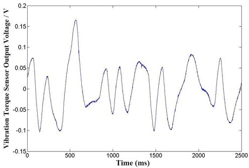
Stepping motor and homemade vibration torque sensor are connected coaxially, three phase three clap and six clap of single step operation without load, the vibration torque of motor are shown in Figures 1 and 2 respectively.
Fig. 1Vibration torque on three phases single three claps
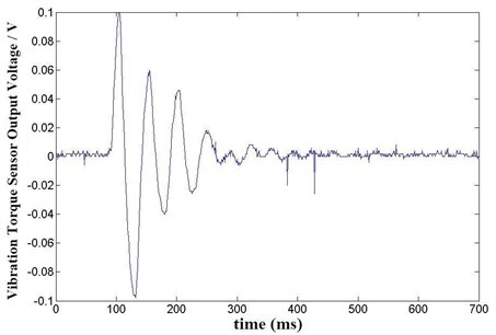
Fig. 2Vibration torque on three phases six claps
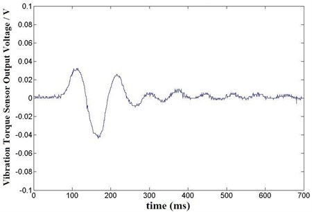
From the experimental results, the vibration torque amplitude of stepper motor operation in three-phase three beat is greater than six beat, the reasons are shown in Fig. 3.
Fig. 3Torque angle characteristic of stepping motor
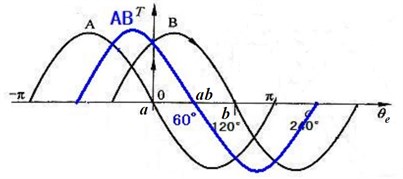
In Fig. 3, sine wave is the torque angle characteristic of stepping motor when phase windings going through DC current; sine wave is the torque angle characteristic of stepping motor when phase windings going through DC current; sine wave is the torque angle characteristic of stepping motor when phase windings and phase windings going through DC current at the same time; then:
Energizing sequence for stepping motor working on single three clap is ; and six clap is . The staring position is , which is the balance position of angle characteristic , and this time ; if phase windings going through DC current, the angle characteristic change into instantaneously, and the static torque is:
If and phase windings going through DC current simultaneously, the angle characteristic change into instantaneously, and the static torque is:
Therefore, if stepping motor operation on single step, the torque fluctuation amplitude of three clap and six clap are same in theoretically when take changing electric pulses, but due to the rotor must be turning and then the sensor output signals, it is namely the stepping motor rotor has turned certain angles. As shown in Fig. 3, it is known that the static torque of three clap is bigger than six clap, then leading to the large vibration torque.
In addition, when the stepper motor operating on no-load, as shown in Fig. 3, the acceleration interval of three clap is 120 electrical degrees, and the acceleration is increased firstly and then decreased; the acceleration interval of six clap is 120 electrical degrees, and the acceleration is always decreased.
The rotor is effected not only by the static torque, but also by the air friction resistance torque and bearing friction resistance torque during actual operation, so the acceleration interval is less than the theoretical value, and we still know that acceleration interval of three clap is greater than six clap. So, the rotor speed at balance position of three clap operation is greater than at the balance position of six clap operation. Due to the inertia, the rotor is not stop immediately when reaches the equilibrium position, and its rotation direction will away from the equilibrium position, which is similar to the pendulum motion process. The function of static torque is drive the rotor to return the balance position, so stepping motor rotor will produce reciprocating motion, and the six clap operation will generate obvious reciprocating oscillation than three clap operation.
4.2. Experiment 2
Stepping motor and homemade vibration torque sensor are connected coaxially, three claps of single step operation without load, and the frequency of pluses are about 2 Hz, the vibration torques are shown in Fig. 4.
According to Fig. 4, the vibration torque of rotor do not influence each other on low frequency continuous operation, because the next step is always coming when the forth step reaches steady state.
4.3. Experiment 3
Stepping motor and homemade vibration torque sensor are connected coaxially, three claps of single step operation without load, and the frequency of pluses are about 170 Hz, the vibration torque is shown in Fig. 5.
The reason of stepper motor lost steps is shown in Fig. 6, the stepper motor rotor is located in the equilibrium position when the phase windings going through DC current, then the phase windings power cut off and phase windings power turn on, the rotor is turning to balance position under the affection of static torque, and it is an accelerated state in the process; when the rotor reaches balance position , a reply oscillation will be generated on the rotor due to the inertia; if the rotor is at the position , then phase windings power cut off and phase windings power turn on, the rotor is subjected to static torque which direction is negative as shown in Fig. 10, and the speed at the same direction, so the rotor is to acceleration at negative direction, which causes the stepping motor generates lost step; and according to the graph 6, there is a static torque jump at position ,which changes static torque positive into negative, and it is always negative in the location process ; if the phase windings going through DC current at this process, there will generate another static torque jump, which is driving the static torque from negative to positive; and the stepper motor is generated intense torque fluctuation if this processes is repeated.
Fig. 4Vibration torque on low frequency continuous operation
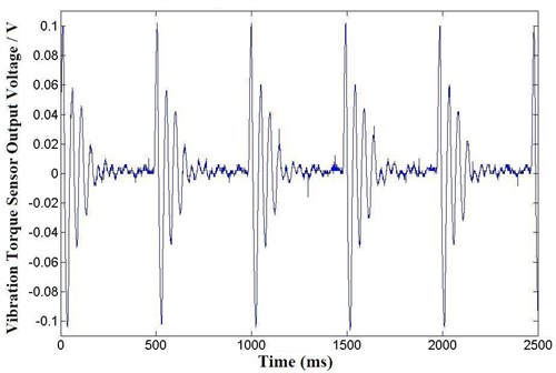
Fig. 5Vibration torque on low frequency oscillation of lost step
4.4. Experiment 4
Stepping motor and homemade vibration torque sensor are connected coaxially, three claps of single step operation without load, and the frequency of pluses are about 300 Hz, 375 Hz and 460 Hz, the vibration torques are shown in Fig. 7.
Fig. 6Principle analysis of low frequency lost step oscillation
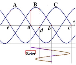
Fig. 7Vibration torque on differences pulse frequency
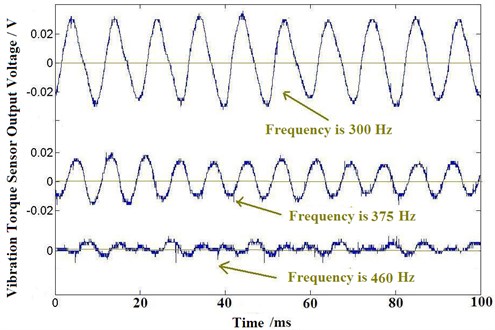
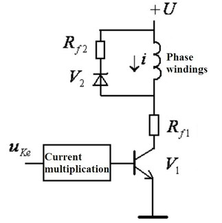
Fig. 8Stepping motor driver circuit of each phase windings
According to experimental results, the stepper motor torque fluctuation is reduced gradually with increasing the frequency, and compared Fig. 1 with Fig. 7, the torque ripple amplitude on continuous operation is smaller than on the single-step operation. The reason for this is shown in Fig. 8.
Fig. 8 is the driving circuit of each phase windings of the stepping motor, is the driving voltage pulses; is the triode, in order to amplify the windings current, is the limiting resistor; the windings discharge circuit is formed by and ; is the DC voltage of windings; when a pulse through the triode , the current is generated in phase windings.
Due to the phase windings existence inductance, the phase windings average current will be reduced when the pulse frequency is increased, as the Eq. (13) shows, the maximum static torque is proportional to the square average current of windings, so the amplitude of motor torque angle characteristic is decreased with the pulses frequency increased. Besides, the stepper motor speed is up with improving the pulse frequency, then the friction resistance moment becomes larger, and according to the torque balance Eq. (14), the torque fluctuation amplitude will be reduced.
Table 1Experiments data
Frequency of stepper motor / Hz | Vibration torque sensor peak voltage / V | Average voltage / V | ||
200 | 0.198 | 0.192 | 0.194 | 0.195 |
225 | 0.136 | 0.138 | 0.14 | 0.138 |
250 | 0.094 | 0.092 | 0.094 | 0.093 |
275 | 0.08 | 0.078 | 0.08 | 0.079 |
300 | 0.062 | 0.064 | 0.062 | 0.063 |
325 | 0.05 | 0.052 | 0.05 | 0.051 |
350 | 0.04 | 0.042 | 0.042 | 0.041 |
375 | 0.032 | 0.036 | 0.03 | 0.034 |
400 | 0.026 | 0.024 | 0.024 | 0.025 |
425 | 0.018 | 0.016 | 0.018 | 0.017 |
450 | 0.012 | 0.01 | 0.008 | 0.01 |
Fig. 9Stepping motor vibration torque peak value-frequency curve
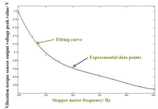
In order to acquire the relationship between the stepper motor vibration torque peak value and frequency of the normal continuous operation, experiment 4 is operated several times, and the results data are shown in Table 1, the experiments data of Table 1 were fitted by a polynomial function as shown in Fig. 9, and the corresponding mathematical expressions are obtained as Eq. (22):
In this equation and the SSE is 0.0000542; R-square is 0.9983; adjusted R-square is 0.9972; RMSE is 0.0003005.
5. Conclusions
The static torque of stepping motor is induced through the law of conservation of energy in this article, so the stepper motor mathematical model is gained, and it is studied by comparing with the torsion pendulum motion mathematical model. Stepper motor torque fluctuations were tested, including single-step operation, low frequency operation, low frequency lost step operation and high frequency operation, the test results are analyzed, and the corresponding conclusion are received. In order to reduce the torque fluctuation of motor on the practical operation, the following work and research is to design a new step motor controller, which controls the winding current input according to the torque fluctuation, it can improve the performance and extend the application range of stepping motor.
References
-
P. Krishnamurthy, F. Khorrami TriM: an ultra-accurate high-speed six degree of freedom manipulator using planar stepper motors. Journal of Intelligent and Robotic Systems, Vol. 51, Issue 2, 2008, p. 137-157.
-
Maki K. Rashid, Zahi A. Khalil Configuration design and intelligent stepping of a spherical motor in robotic joint. Journal of Intelligent and Robotic Systems, Vol. 40, Issue 2, 2004, p. 165-181.
-
P. Melin, O. Castillo Intelligent control of a stepping motor drive using a hybrid neuro-fuzzy approach. Soft Computing, Vol. 8, Issue 8, 2004, p. 546-555.
-
Tomoaki Yano Simulation results of a hexahedron octahedron based spherical stepping motor. Journal of Mechanical Science and Technology, Vol. 24, Issue 1, 2010, p. 33-36.
-
Hong Min Zheng, Wen Feng Cui Design of controlling system for linear stepper motor based on DSP2407. Advances in Electronic Commerce, Web Application and Communication Advances in Intelligent and Soft Computing, Vol. 149, 2012, p. 335-341.
-
Bo Qu, Hong Lin Design of the stepper motor controller. Electronics and Signal Processing, Lecture Notes in Electrical Engineering, Vol. 97, 2011, p. 525-531.
-
Baoshan You, Liying Pei A novel stepper speed control algorithm based on FPGA. Advances in Computer Science and Education Applications, Communications in Computer and Information Science, 2011, p. 202-209.
-
Pan Jin-Yu Analysis and determination of stepping motor rotation stability. Aerospace Shanghai, Vol. 22, Issue 5, 2005, p. 54-57.
-
Sun Yao-Jie, Zuo He, Kang Long-Yun Time-varying repetitive control of restraining torque ripple for hybrid stepping motor system. Proceedings of ME CSEE, Vol. 24, Issue 11, 2004, p. 18-17.
-
Zheng Xiao-Dong, Zou Kun, Sun Yi-Ze Rotating speed fluctuation and response speed of two-phase hybrid type stepping motor. Journal of Donghua University (Natural Science), Vol. 35, Issue 4, 2009, p. 463-487.
-
Zhao Hao, Feng Hao Research of a new permanent magnet angular acceleration sensor based on electromagnetic induction. Chinese Journal of Sensors and Actuators, Vol. 25, Issue 9, 2012, p. 1257-1261.
About this article
The work was sponsored by in part by the Jiaxing Science and Technology Research Project of China under Grant (2012AY1021), in part by the Zhejiang Provincial Department of Education Scientific Research Project of China under Grant (Y201226082), in part by the Zhejiang Province Major Science and Technology Project of China under Grant (2008C01011-4) and in part by the Jiaxing University Nanhu College Key Scientific Research Project.
