Abstract
The method of investigation of morphology of the surface of flock materials using a photoelement is proposed. Two methods which enable to improve the quality parameters of such materials in the process of their production are investigated. They are based on excitation of a tape of flock material by using vibrations of definite characteristics using different types of vibration exciters. Diagnostics of geometrical locations of glued hairs on the surface of flock material has been performed. It is shown that by exciting definite modes of vibrations on the surface of flock material it is possible to make the hairs glued on the surface of the tape of flock material more continuous and straighter. It is assumed that flock material consists from a number of narrow two dimensional elastic strips with the displacements of the corresponding nodes in the direction of the x axis of adjacent strips being mutually equal. Also in another model of flock material it is assumed that flock material consists from a number of narrow two dimensional elastic strips and between them there are narrow gaps. The gaps are assumed to have small stiffness in the direction of the x axis. For both models of flock material the first eigenmodes are determined and investigated. The obtained results indicate that from the locations of elastic elements with respect to each other on the upper surface of flock material it is sometimes possible to identify the number of eigenmode. So the measurement of the number of excited eigenmode can be performed from the interpretation of the image of the upper surface of flock material. But sometimes the image indicating the motion of elastic elements over their length is required. The obtained results are used in the process of measurement of eigenmodes performing design of packages made from flock material.
1. Introduction
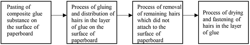
In recent years for packaging of exceptional souvenir type products the flock printing materials find wide application, because they have exceptionally nice visual appearance. The technological process of production of such materials consists from the stages shown in Fig. 1.
Fig. 1Stages of technological process of production of flock printing materials
If there are violations at least in one of those stages during the process of production the material with defects is produced. There may be various defects of coating of hairs on the basis of paper or paperboard: hairs are located incorrectly, they stick to one another, they are of incorrect shape. Great influence to the quality of such materials have the components which are used: type of glue, type of hairs, such as cotton, viscosis, polyester, nylon.
As shown in microscopic photos (Fig. 2) the hairs glued on the surface of flock printing material are located not continuously, the hairs are glued to one another or have bendings.
Fig. 2Microphoto of flock printing material: a) coated by nylon hairs: diameter – 20 μm, length – 1mm [1]; b) image of the material with glued flock enlarged by the electronic microscope, where: 1 – the background material, 2 – the layer of glue, 3 – the glued flock [2]
![Microphoto of flock printing material: a) coated by nylon hairs: diameter – 20 μm, length – 1mm [1]; b) image of the material with glued flock enlarged by the electronic microscope, where: 1 – the background material, 2 – the layer of glue, 3 – the glued flock [2]](https://static-01.extrica.com/articles/10006/10006-img2.jpg)
a)
![Microphoto of flock printing material: a) coated by nylon hairs: diameter – 20 μm, length – 1mm [1]; b) image of the material with glued flock enlarged by the electronic microscope, where: 1 – the background material, 2 – the layer of glue, 3 – the glued flock [2]](https://static-01.extrica.com/articles/10006/10006-img3.jpg)
b)
A number of papers are devoted to the investigations of morphology of the surface of flock materials. By applying various methods and devices (atomic force microscope, electronic spectroscope, time of flight secondary ion mass spectrometry) investigations of morphology of surfaces of various materials have been performed [3-6].
But in the above mentioned papers the morphology of the surface of flock materials has not been investigated. Thus the main purpose of this paper is to propose a method for the measurement of geometry and diagnostics of hairs of flock material.
The problem of straightening of hairs in the flock printing material may be solved by investigating the eigenmodes of vibrations of hairs, when they are excited by an external generator of vibrations by using vibrations from various frequency intervals.
The model for the analysis of vibrations of flock printing material is proposed on the basis of the material presented in [7, 8].
A flocked finish imparts decorative and/or functional characteristics to the surface. Quality of the flock is strongly influenced by the flock density on the finished flock surface. The flock density depends on flock motion in the electric field. The flock motion analyses found in the literature are based on simplified physical constraints in the flocking zone and charges on flocking fibers [3-6].
The use of superfine fibers as piles to produce flocked fabrics is underreported despite their excellent properties. Therefore, a superfine polyamide fiber was used for piles to produce flocked fabric in those studies, and a full factorial design was employed with three design factors at three levels to optimize the process parameters in terms of flocking density [7-10].
In the research papers [11-12] the authors by using the electronic microscope investigated the influence of the structure of the surface of the paper and paperboard, of the flock type and its parameters and also of various additives in the coated material to the orientation of the glued flock. Some related investigations of characteristics of flock printing materials are presented in [13-19]. The investigations of packages produced from those materials are described in those papers also.
In the first model of flock material it is assumed that flock material consists from a number of narrow two dimensional elastic strips with the displacements of the corresponding nodes in the direction of the axis of adjacent strips being mutually equal. An element with linear interpolation in the direction of the local coordinate and with quadratic interpolation in the direction of the local coordinate is used. But it is assumed that each degree of freedom of the element is a separate node. Thus the element has 12 nodes with one degree of freedom in each of them. This enables to easily implement the described conditions of equal displacements in the direction of the axis, while the displacements in the direction of axis are not necessarily equal.
In the second model of flock material it is assumed that flock material consists from a number of narrow two dimensional elastic strips and between them there are narrow gaps. The gaps are assumed to have small stiffness in the direction of the axis.
The first eigenmodes for both models of flock material are determined and investigated.
For the flock printing materials higher requirements of mechanical strength are applied: for bending, vibrations, compression and so on. Thus, in this paper vibrations of flock printing materials are investigated experimentally for two cases: when the material is of good quality and when it has defects.
The obtained results are used in the process of measurement of eigenmodes performing the design of packages made from flock material.
2. Measurement of morphology of surface of flock printing material
For the estimation of morphology of surface of flock printing materials optical method of measurement is proposed. It is shown in Fig. 3. The presented data of measurement show rather great non uniformities of the surface of flock printing material (see Fig. 4).
Fig. 3Schematic representation of measurement of morphology of the surface of flock material, where: 1 – flock material, 2 – tube, 3 – photodiode
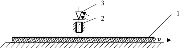
Fig. 4Morphology of the surface of flock material: S – width of a sheet of paperboard, h – height of non uniformities of the surface
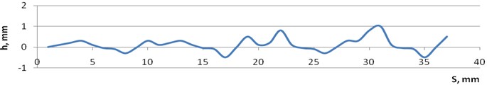
The obtained results of investigations enable to conclude that it is necessary to look for methods for improvement of the quality of such materials.
3. Proposed methods for improvement of quality parameters of flock materials
Flocking process is usually performed by using the electrostatic method (Fig. 5). But this method does not ensure uniform glueing of hairs in the layer of glue on the paper or paperboard. Also the glued hairs on the surface of paperboard experience bending (see Fig. 2).
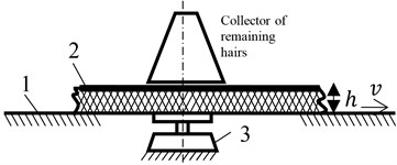
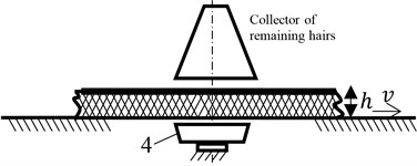
During the process of production of flock material the application of two technological methods is proposed: the electrodynamical (Fig. 6a) and the acoustical (Fig. 6b) methods of excitation of vibrations.
Fig. 5Simplified diagram of the technological process of flock glueing by applying the electrostatic method [13]
![Simplified diagram of the technological process of flock glueing by applying the electrostatic method [13]](https://static-01.extrica.com/articles/10006/10006-img6.jpg)
Fig. 6Electrodynamical (a) and acoustical (b) methods of excitation of vibrations for straightening of hairs glued in the flock material, where: h – amplitude of vibrations, v – velocity of motion of the tape of paper, 1 – directing elements, 2 – tape of paper, 3 – electrodynamic exciter of vibrations, 4 – acoustic exciter of vibrations
a)
b)
The use of such technical solutions by applying vibrations of some specified characteristics to the produced material substantially improves qualitative parameters of the surface of flock material.
The quality of surface of flock material may be improved by exciting eigenmodes of vibrations of flock material. Further numerical investigation of such eigenmodes is performed.
4. Diagnostics of geometry of location of hairs on the surface of paperboard in flock material
4.1. Model of flock printing material without gaps
Further and denote the axes of the system of coordinates. The local coordinates of the nodes are (–1, –1), (1, –1), (–1, 0), (1, 0), (–1, 1), (1, 1) and the corresponding shape functions are , 1, 2, …, 6. It is assumed that each node is repeated twice and thus the finite element has 12 nodes. The first node with local coordinates (–1, –1) represents the displacement in the direction of the axis. The second node with local coordinates (–1, –1) represents the displacement in the direction of the axis. The third node with local coordinates (1, –1) represents the displacement in the direction of the y axis. The fourth node with local coordinates (1, –1) represents the displacement in the direction of the axis. The fifth node with local coordinates (–1, 0) represents the displacement in the direction of the axis. The sixth node with local coordinates (–1, 0) represents the displacement in the direction of the axis. The seventh node with local coordinates (1, 0) represents the displacement in the direction of the axis. The eighth node with local coordinates (1, 0) represents the displacement in the direction of the axis. The ninth node with local coordinates (–1, 1) represents the displacement in the direction of the axis. The tenth node with local coordinates (–1, 1) represents the displacement in the direction of the axis. The eleventh node with local coordinates (1, 1) represents the displacement in the direction of the axis. The twelfth node with local coordinates (1, 1) represents the displacement in the direction of the x axis.
The following matrixes of shape functions are introduced:
The jacobian is calculated as:
where and are the coordinates of the nodes.
Thus it is obtained:
The matrix of shape functions relating displacements inside the element with the nodal displacements has the following form:
The matrix relating strains inside the element with the nodal displacements has the following form:
Those matrixes are used in the usual expressions of the mass and stiffness matrixes of the plane strain problem.
4.2. Results of analysis of vibrations of flock printing material without gaps
Length of the structure is equal to 0.2 m and thickness of the structure is equal to 0.08 m. The following parameters are assumed: modulus of elasticity 6×10⁸ Pa, Poisson’s ratio 0.3, density of the material 785 kg/m3.
On the lower boundary all the displacements are assumed equal to zero. 64 elastic strips are taken into account.
The first eigenmode is presented in Fig. 7, the second eigenmode is presented in Fig. 8, …, the seventh eigenmode is presented in Fig. 13.
Fig. 7The first eigenmode
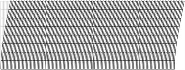
Fig. 8The second eigenmode
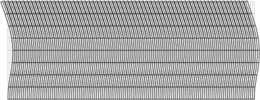
Fig. 9The third eigenmode
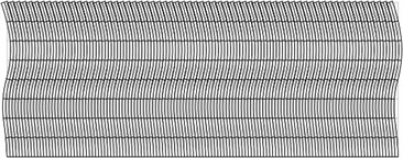
Fig. 10The fourth eigenmode
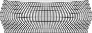
Fig. 11The fifth eigenmode
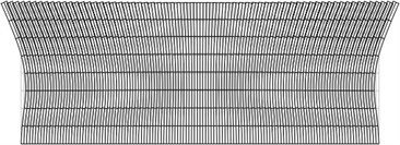
Fig. 12The sixth eigenmode
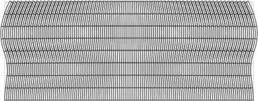
Fig. 13The seventh eigenmode
From the obtained results it is seen that adjacent elastic elements of flock material move together in the direction of axis, while in the direction of axis slippage of adjacent elastic elements with respect to one another takes place. Thus the obtained results indicate that from the locations of elastic elements with respect to each other on the upper surface of flock material it is sometimes possible to approximately identify the number of eigenmode. So the measurement of the number of excited eigenmode can be approximately performed from the interpretation of the image of the upper surface of flock material. But sometimes the image indicating the motion of elastic elements over their length is required, for example in order to identify the difference between the first three eigenmodes.
As indicated by experimental investigations the hairs on the surface of flock material may be straightened under the action of vibrations of various frequency ranges (from 110 Hz up to 950 Hz).
4.3. Model of flock printing material with gaps
and denote the axes of the system of coordinates. Each node has two degrees of freedom: the displacement in the direction of the axis and the displacement in the direction of the axis. Usual expressions of the mass and stiffness matrixes of the plane strain problem are assumed for the flock material, while the gap is represented as having only longitudinal stiffness.
Thus the stiffness matrix of the element of the gap:
where is the modulus of elasticity in the direction of the axis and:
where , 1, 2, …, 6 are the shape functions of the finite element.
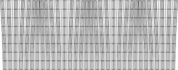
Fig. 14The first eigenmode
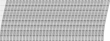
Fig. 15The second eigenmode
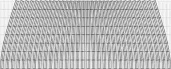
Fig. 16The third eigenmode

Fig. 17The fourth eigenmode
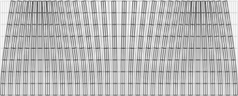
Fig. 18The fifth eigenmode
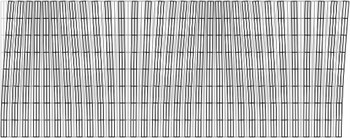
Fig. 19The sixth eigenmode
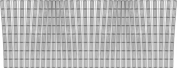
Fig. 20The seventh eigenmode
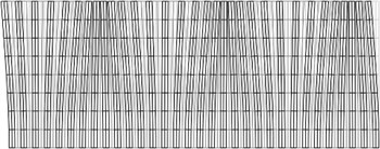
Fig. 21The eighth eigenmode
4.4. Results of analysis of vibrations of flock printing material with gaps
Length of the structure is equal to 0.2 m and thickness of the structure is equal to 0.08 m. The following parameters of flock material are assumed: modulus of elasticity 6×10⁸ Pa, Poisson’s ratio 0.3, density of the material 785 kg/m3. The modulus of elasticity of the gaps 8000 Pa.
On the lower boundary all the displacements are assumed equal to zero. 63 strips are taken into account: odd strips represent elastic flock material and even strips represent gaps.
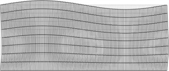
The first eigenmode is presented in Fig. 14, the second eigenmode is presented in Fig. 15, the eighth eigenmode is presented in Fig. 21.
From the obtained results it is seen that the vibrations of each elastic element takes place according to the first eigenmode of bending vibrations of a beam. The gaps synchronize the vibrations of elastic elements. Thus on the upper surface of flock material the intervals between the elastic elements in the higher eigenmodes are gradually changing. From the locations of elastic elements with respect to each other on the upper surface of flock material it is possible to identify the number of eigenmode. Thus the measurement of the number of excited eigenmode is performed from the interpretation of the image of the upper surface of flock material.
5. Conclusions
The method of investigation of morphology of the surface of flock material is proposed. It is based on the use of the optical principles.
Two technological solutions which enable to improve the quality of flock materials by using vibrations are proposed.
Diagnostics of geometry of location of hairs located on the surface of paperboard is performed.
It is shown that by exciting definite eigenmodes of vibrations of hairs located on the surface of material it is possible to make them continuous and straight.
Two models of flock material are proposed. The first model is without gaps, while the second one is with gaps.
For the model of flock material without gaps on the lower boundary of the investigated structure all the displacements are assumed equal to zero. Totally 64 elastic strips are taken into account. The first seven eigenmodes are determined and investigated.
The proposed approach of considering each degree of freedom as a separate node enables to easily implement the necessary boundary conditions and to investigate the interaction of elastic elements of the flock material. From the obtained results it is seen that adjacent elastic elements of flock material move together in the direction of axis, while in the direction of axis slippage of adjacent elastic elements with respect to one another takes place. Thus the obtained results indicate that from the locations of elastic elements with respect to each other on the upper surface of flock material it is sometimes possible to approximately identify the number of eigenmode. So the measurement of the number of excited eigenmode can be approximately performed from the interpretation of the image of the upper surface of flock material. But sometimes the image indicating the motion of elastic elements over their length is required, for example in order to identify the difference between the first three eigenmodes.
For the model of flock material with gaps on the lower boundary of the investigated structure all the displacements are assumed equal to zero. Totally 63 strips are taken into account: odd strips represent elastic flock material and even strips represent gaps. The first eigenmodes are determined and investigated.
From the obtained results it is seen that the vibrations of each elastic element takes place according to the first eigenmode of bending vibrations of a beam. The gaps synchronize the vibrations of elastic elements. Thus on the upper surface of flock material the intervals between the elastic elements in the higher eigenmodes are gradually changing. From the locations of elastic elements with respect to each other on the upper surface of flock material it is possible to identify the number of eigenmode. Thus the measurement of the number of excited eigenmode is performed from the interpretation of the image of the upper surface of flock material.
The obtained results are used in the process of measurement of eigenmodes while performing the design of packages made from flock material.
References
-
Burkhart J., Piacitelli C., Schwegler-Berry D., Jones W. Enviromental study of nylon flocking process. J. Toxicol. Environ. Health A, Vol. 57, 1999, p. 1-23.
-
Sudeep Vaswani, Jere Koskinen, Dennis W. Hess Surface modification of paper and cellulose by plasma-assisted deposition of fluorocarbon films. Surface and Coatings Technology, Volume 195, Issues 2-3, 2005, p. 121-129.
-
Chong P. H., Man H. C., Yue T. M. Microstructure and wear properties of laser surface-cladded Mo–WC MMC on AA6061 aluminum alloy. Surface and Coatings Technology, Volume 145, Issues 1-3, 2001, p. 51-59.
-
Krista Koljonen, Monika Österberg, Marjatta Kleen, Agneta Fuhrmann Precipitation of lignin and extractives on kraft pulp: effect on surface chemistry, surface morphology and paper strength. Cellulose, Vol. 11, 2004, p. 209-224.
-
Maximova N., Osterberg M., Koljonen K., Stenius P. Lignin adsorption on cellulose fibre surfaces. Effect of surface chemistry, surface morphology and paper strength. Cellulose, Vol. 8, 2001, p. 113-125.
-
Ragulskis M., Ragulskis L. Plotting isoclinics for hybrid photoelasticity and finite element analysis. Experimental Mechanics, Vol. 44, 2004, p. 235-240.
-
Zienkiewicz O. C. The Finite Element Method in Engineering Science. Moscow: Mir, 1975.
-
Bathe K. J. Finite Element Procedures in Engineering Analysis. New Jersey: Prentice-Hall, 1982.
-
Kleber W., Schmidt H. J. Computer aided optimizing of electrical fields for flocking operation. Proceedings of 11th International Flock Seminar, Buedingen, Germany, 1992, p. 10-1 to 10-24.
-
Bershev E. N. Developing the Physical Principles of Electrostatic Flocking Procedures. Moscow, 1977.
-
Kim Y. K., Lewis A. F. F97-D01: “Scientific Study of Flock Materials and the Flocking Process”. Annual Report 1998, National Textile Center, 1998.
-
Bershev Е. N., Lobov V. F. Technology and Equipment for Nap Causing in the Powerful Electric Fields. Moscow: VNIIESM, 1976, 60 p., (in Russian).
-
Zhong J., Liu L. F., Yu J. Y., Xie H. Electrostatic flocking of superfine fiber. Proceedings of International Conference on Fibrous Materials,China, 2009, p. 276-278.
-
Yang S. Z., Yu J. Y., Liu L. F.,Yang J. S. Investigation on electrostatic flocking process of sea-island fiber. Textile J., Vol. 28(7), 2007, p. 9-11, 18, (in Chinese).
-
Sung B. J., Aly A., Lee S. H., Takashima K., Kastura S., Mizuno A. Fine-particle collection using an electrostatic precipitator equipped with an electrostatic flocking filter as the collecting electrode. Plasma Process. Polym., Vol. 9, 2006, p. 661-667.
-
Lifang Liu, Longdi Cheng, Jianyong Yu, Hao Xie Evaluation of the availability of easy cationic dyeable copolyester fibers as electrostatic flocking piles. Journal of Applied Polymer Science, Volume 120, Issue 1, 2011, p. 195-201.
-
Havenko S., Mizyuk O., Rybka R., Kibirkštis E., Zubrickaitė L. Study of physical aspects of electro-flocking (flock printing). J. Materials Science (Medžiagotyra), 2007, Vol. 13, No. 3, p. 206-209.
-
Mizyuk O., Kibirkštis E. Study of mechanical characteristics of package from flock printing materials at compression. Strain. Malden: Blackwell Publishing Ltd., Vol. 46, No. 2, 2010, p. 205-208.
-
Kabelkaitė-Lukoševičė A., Gegeckienė L., Kibirkštis E., Havenko S., Bivainis V., Ragulskis K., Ragulskis L. Analysis of vibrations and stability of flock printing material. Journal of Vibroengineering, Vol. 13, No. 2, 2011, p. 237-244.
About this article
