Abstract
The article is devoted to the development of a vehicle suspension with a nonlinear characteristic based on a torsion bar and an elastic hinge with a given characteristic on the example of tracked vehicles for constructing oil and gas pipelines. The characteristic of the elastic hinge is such that when the existing torsion bar suspension and the elastic hinge are connected in parallel, the desired characteristic is obtained. For this non-linear characteristic in the static displacement region, low stiffness was obtained, but the total stored energy at the maximum deflection of the balance bar of the resulting suspension is greater than that of existing torsion suspensions. The smoothness of the tracked vehicles with a low stiffness of the suspension increases significantly. The calculation of vibrations of the proposed suspension under kinematic excitation was carried out. A harmonic function is considered as the trajectory of the profile; a function corresponding to a single obstacle and a function corresponding to an ascent to a ledge of a given height. The elastic hinge is a pneumatic spring moving between the guides of the design form. The force characteristic of the hinge depends on the shape of the guides and on the pressure in the air spring. The calculation of the circular shapes of the guides of the elastic hinge is given. The values of the forces arising between the pneumatic spring and the guides are determined.
1. Introduction
Torsion bar suspensions are widely used in tracked vehicle suspensions [1], such as bulldozers, excavators, etc. A torsion bar suspension is a combination of a torsion bar (an elastic shaft) and a balancer, which converts the torque on the torsion bar into a vertical force that perceives the weight of the vehicle. Through the suspension on the body are transmitted impacts from the side of road irregularities. Their advantages are simplicity and reliability, ease of layout. The advantages of a torsion bar suspension compared to leaf springs are lighter weight, higher energy consumption, and better layout options [2]. Torsion suspensions are also used for cars [3]. One of the most important requirements for modern tracked vehicles used in the construction of oil and gas pipelines is to increase mobility when driving over rough terrain [4]. Torsion suspensions are widely used, in particular, in in vehicles used in the construction of oil and gas pipelines [5]. The force characteristic of the torsion suspension is close to linear [5]. The stiffness of the suspension is one of the most important parameters that determine the smoothness of the tracked vehicle. The lower the stiffness of the suspension, the smoother the ride of the car. Rigid suspensions are characterized by significant vertical accelerations of the hull from uneven terrain, which reduces people comfort.
With a linear suspension characteristic, it is impossible to obtain a working area with a given low stiffness, which is so important for tracked vehicles. This is only possible with a non-linear characteristic. It should be noted systems with quasi-zero stiffness, first proposed by Professor Alabuzhev P. M. [6]. These vibration protection systems have non-linear power characteristics with a quasi-zero stiffness section. Most modern systems with quasi-zero stiffness are varieties of Alabuzhev systems, in which the region with quasi-zero stiffness is obtained by adding the characteristic of the von Mises system with a region of negative stiffness to the characteristic of a spring with positive stiffness, for example, [7]. It is possible to obtain systems with quasi-zero stiffness using vibration isolators, in which an elastic element, a spring or an air spring, moves between the guides of the design form [8]. In this case, due to this form, it is possible to obtain a wide variety of types of power characteristics. There are elastic hinges with a given angular force characteristic (the dependence of the restoring moment on the angle of rotation), in which the elastic element moves between the angular guides of the design form [9].
The idea of this work is the parallel connection of the elastic hinge to the torsion bar suspension. The characteristic of the elastic hinge is such that when it is added to the characteristic of the torsion bar suspension, the “desired” characteristic of the proposed suspension is obtained. In the region of the static displacement of the suspension, low stiffness was obtained, which helps to improve the smoothness of the transport vehicles. But the energy stored by the proposed suspension with a non-linear characteristic, at the maximum displacement, is greater than the energy stored by the classical torsion bar suspension at the same displacement.
2. Suspension with nonlinear force characteristics, having a part with a given low stiffness
Consider obtaining the desired characteristics with a low stiffness section using the example of one torsion bar suspension of the DET 320 or DET 400 bulldozers. The number of torsion bar suspensions of the bulldozer is 12. Assume the mass per torsion equal to 3200 kg [5]. We take the mass acting on one torsion bar suspension as the mass of the bulldozer divided by the number of suspensions. Let us take the average stiffness of the bulldozer suspension as 220 kN/m [5].
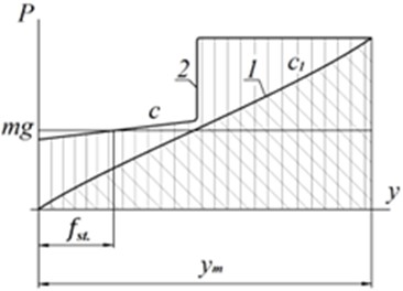
The task of this study is to obtain a characteristic with low stiffness, and at the same time, so that the stored energy at maximum suspension travel is significantly greater than that of the existing one (Fig. 1(a) curve 1, ). It is proposed to obtain characteristic 2. In the working area determined by the static displacement under the action of gravity of the suspended mass mg, we will have a given low stiffness . This stiffness is significantly less than the stiffness of , which will increase the smoothness of the vehicle. As can be seen from the figure, the area under curve 2 is noticeably larger than the area under curve 1. Fig. 1(b) shows the proposed “desired” suspension characteristic after loading.
Fig. 1Suspension force characteristics: a) 1 – classic torsion bar suspension; 2 – proposed characteristic; bb) performance after loading with a given mass
a)
b)
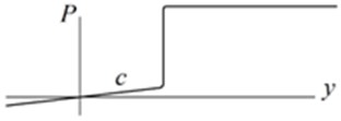
In fact, the force characteristic of the torsion bar suspension is not strictly linear due to the classical design, in which the torque of the torsion bar is converted into a vertical force due to a balancer with a length (Fig. 2(a)). We accept 0.38 m. The vertical displacement of the end of the balance bar (point A) depends on the angle of rotation of the torsion bar and is described by Eq. (1):
where is the initial deviation of the balancer relative to the horizontal, we accept 49° [5].
Since Eq. (2) is valid, Eq. (3) determines the relationship between the force and the angle :
where is the arm of the action of the vertical force relative to the center of rotation of the balance bar; – torsional stiffness of the torsion bar [5]. Accepted value:
where from Eq. (1).
The intersection of this curve and gravity determines the static displacement 0.14 m. The idea of this study is to obtain a non-linear characteristic 2 (Fig. 2(b)). In the region of static displacement, 0.09 m a low stiffness was obtained. To increase the energy stored by the proposed suspension at maximum displacement, the shape of the non-linear characteristic is such that in a certain area (in this example from 0.18 m to 0.35 m) the restoring force is constant (). This energy determines the height at which the vehicle is dropped and the suspension breaks down.
The shape of curve 2 (Fig. 2(b)) is given by the following formula:
where 0.18 m; 50000 N/m; 9.82 m/s2; 0.35 m and:
The proposed characteristic 2 can be obtained by adding to the existing characteristic 1 for the torsion bar suspension Eq. (3), which is obtained by the following formula:
Eq. (3) according to Eq. (5) is shown in Fig. 2(b). This dependence is supposed to be obtained with the help of an elastic hinge 3 (Fig. 2(a)).
Natural frequency of the considered torsion bar suspension before changes 8.28 s-1. After installing elastic hinges, the natural frequency will decrease by more than half. 3.95 s-1. If necessary, it is possible to achieve stiffness of the resulting suspension 0, but in this case, a change in the mass of the vehicle is no longer desirable.
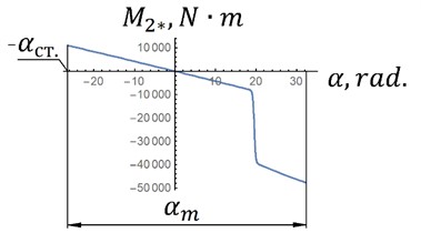
The angular characteristic of the elastic hinge is determined by Eq. (6):
where is the equation according to Eq. (4) with the change of variable according to Eq. (1).
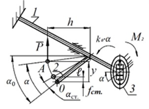
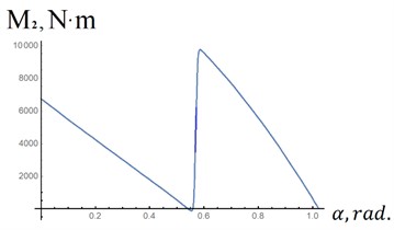
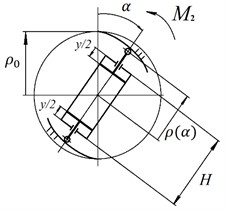
The equation according to Eq. (6) is shown in Fig. 3(a). To obtain this characteristic, an elastic hinge is designed, the scheme of which is shown in Fig. 3(b). The pneumatic spring moving between the guides of the design form is made with symmetrical pistons. The guides are shaped so that the reactions between the air spring and the guides create a given moment . It is assumed that the guides of the elastic hinge are rigidly connected to the vehicle body, and the air spring is connected to the torsion bar (Fig. 2(a)) (or vice versa).
Fig. 2a) Scheme of the proposed suspension at a parallel connection of the torsion bar and elastic hinge 8 (1 – torsion; 2 – balancer; 3 – elastic joint with a given characteristic); b) force characteristics (1 – force characteristics of torsion suspension; 2 – proposed force characteristic of the torsion suspension; 3 – force characteristic of the elastic joint); l= 0.38 m; α0= 49°; αCT.= 26.27°; k0= 23698 (N∙m)/rad; f1CT= 0.14 m; f2CT.= 0.09 m; ym= 0.35 m; y0= 0.18 m; c= 50000 N/m; m= 3208 kg
a)

b)
The results of previous calculations are summarized in Table 1.
Table 1Suspension parameters of standard values for equipment operating parameters
Parameter | Suspension stiffness, N/m | Stored energy at maximum suspension compression, J | Suspension natural frequency, s-1 |
Torsion bar suspension | 22000 | 12384.2 | 8.28 |
Linear suspension with low stiffness | 50000 | 10290 | 3.95 |
Nonlinear characteristic | 50000 | 15087.8 | 3.95 |
Let’s calculate the energy stored by the torsion bar suspension (curve 1), the proposed suspension (curve 2) and the suspension with low rigidity (indicated by the dotted line, Fig. 2(b). To do this, we numerically integrate these three dependencies from 0 to . For the variant shown in Fig. 2, the following results were obtained. For curve 1, 12384.2 J; for curve 2 – 15087.8 J; for a linear dependence with stiffness –10290 J. That is, a suspension with low stiffness (shown by hatching, Fig. 2(b) does not meet the requirements for tracked vehicles. But for the proposed characteristic, the stored energy is much greater. When changing the parameters of characteristic 2, for example, increasing the constant force, this excess can become even greater.
Fig. 3a) Angular characteristic of the elastic joint; b) scheme of elastic hinge
a)
b)
3. Calculation of guides of elastic hinge
To determine the shape of the guides of the elastic hinge, the characteristics of which are shown in Fig. 3, we use Eq. (7). We take the radius of the rollers in contact with the guides equal to 0 (Fig. 3(b)). With such an angular response, the resulting response of the proposed suspension will be similar to that in Fig. 2(b) (curve 2):
where – angular characteristic of the elastic hinge; ; is the height of the air spring cylinder; 1.25 – polytropic index; is the diameter of the air spring piston (Fig. 3(b)); – air spring piston area; – initial pressure in the air spring; – displacement of each piston of the air spring; is the polar coordinate; is the initial polar coordinate at .
Consider the left integral Eq. (7) as defined (from 0 to ):
From relation Eq. (8), taking into account Eq. (7), omitting calculations, we obtain:
where is determined numerically.
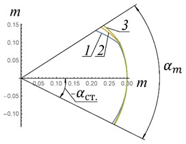
Fig. 4(b) shows the shapes of the elastic hinge guides, calculated by Eq. (9) at different initial pressures in the air spring.
Fig. 4a) characteristic of the elastic hinge; b) shape of elastic hinge guides at different initial pressures in the air spring; 1 – p0= 30∙105 N/m2; 2 – p0=50∙105 N/m2; 3 – p0= 70∙105 N/m2; H= 0.4 m; n= 1.25; Ad=πd2/4; d= 0.2 m; ρ0=H/2+0.1, m
a)
b)
Let’s determine the magnitude of the reactions occurring at the point of contact of the pneumatic spring and the guides. To do this, we will substitute the maximum value of the piston displacement into the formula for determining the restoring force , where . The analysis of Eq. (9) showed that 0.25 m. Then 0.05 m and (3∙106 N/m2) = 111368 N. With such values of reactions, the problem of choosing the material of the elastic hinge guides will arise. Perhaps special shoes will be used instead of rollers to reduce contact pressure.
4. Calculation of oscillations
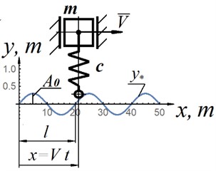
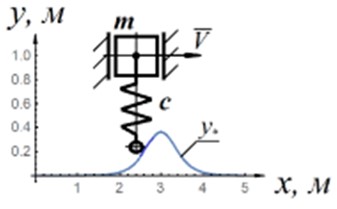
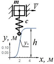
Let us consider oscillations of the sprung mass with the obtained characteristic during kinematic excitation [10] (Fig. 5(a)). Fig. 5(b) shows the proposed force characteristic of the suspension, taking into account the sprung mass. The differential equation describing the fluctuations of the sprung mass in the case of the proposed suspension, taking into account the damper, the resistance force of which is proportional to the first power of the speed, is as follows:
where 3208 kg – the mass attributable to this suspension; – constant coefficient [(N∙c)/m]; – coordinate of the sprung mass; is the profile amplitude; – length of irregularities (Fig. 5(a)); – equation of the profile coordinate on time, and proposed characteristic (with kinematic excitation):
Fig. 5a) design scheme for kinematic excitation of oscillations; b) force characteristic with taking into account the oscillating mass
a)
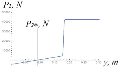
b)
Oscillations in the case of a linear characteristic of a classical torsion suspension (Fig. 2(b) curve 1) are determined by the differential Eq. (11):
where 220 kN/m [10].
When modeling the movement of tracked vehicles by geometric dimensions, the irregularities of typical tracks are usually divided into five types [5]. The first microprofile-irregularities with a height of 0.02-0.05 m. This is a microprofile of a hard pavement of roads. The fith microprofile-irregularities 6-12 m long and 0.25-0.50 m high, and in some cases even more. For calculations, we will accept the following parameters of the route profile: 0.06 m; 0.2 m; 8 m; 20 m/s; 500 N∙s/m.
Fig. 6 shows the oscillations of the sprung mass (Fig. 5(a)) obtained by the numerical solution of differential Eqs. (10) and (11). As can be seen from this example, the oscillation amplitude in the case of low stiffness (Fig. 5(b)) is almost 40 times less than the oscillation amplitude in the case of a classical torsion bar suspension.
Fig. 6a) fluctuations in the sprung mass in the case of the characteristic shown in Fig. 5(b) (P2*); b) fluctuations in the sprung mass in the case of a torsion bar suspension (Fig. 2(b), curve 1)
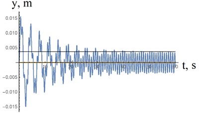
a)10000 N / m
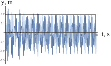
b)220000 N / m
Fluctuations of the sprung mass were investigated when passing a single obstacle and when climbing a ledge of a given height (Fig. 7). We use differential Eqs. (10) and (11). For variant (a), the function , which determines the kinematic excitation, is as follows:
where , , – parameters determining the shape of a single obstacle (Fig. 7(a)).
For case (b), the function is as follows:
where is the height of the ledge; is an arbitrary constant.
When substituting Eq. (12), i.e. kinematic excitation with a single obstacle, Fig. 7(a) and Eq. (13), i.e. kinematic excitation with lifting, into Eq. (10), that describes the vertical movement of the body with the proposed nonlinear suspension characteristic, and 11, that describes the vertical movement of the body with a classical suspension, vibrations of the vehicle body were obtained for the variants of obstacles presented in Fig. 7. For option “a” the maximum displacement of the body turned out to be equal to 0.09 m for the proposed suspension and 0.03 m for the classical suspension at 0.2 m and 500 N·s/m. When lifting (Fig. 7(b), 0.2 m), the maximum displacement of the body for the suspension with the proposed characteristic is 0.2 m. For the classical suspension, the maximum displacement of the body was 0.4 m (the stiffness coefficient of the classical suspension was taken = 220000 N /m with a mass per spring 3200 kg).
Fig. 7Shapes of obstacles: a) a single obstacle; b) a ledge
a)
b)
5. Conclusions
The proposed suspension of vehicles, primarily tracked vehicles, which is a combination of a classical torsion bar suspension and an elastic hinge connected in parallel to the torsion bar, allows obtaining non-linear power characteristics with a working area of low stiffness. The energy stored by the proposed suspension when it is fully compressed can significantly exceed the energy stored by the classical torsion bar suspension, which is relevant, for example, for bulldozers. Due to the given low stiffness in the working section of the characteristics of the proposed suspension, the smoothness of the vehicles is significantly improved. It should be noted that the maximum force transmitted to the body in this case is constant. The proposed suspension can be used not only for tracked vehicles, but also for other vehicles. The suspension considered may be especially relevant for passenger cars. In this case, the maximum reactions between the pneumatic spring and the hinge guides will significantly decrease. The disadvantage of the proposed suspensions is the large reactions between the air springs and their guides. In the future, it is planned to develop specific designs of elastic hinges with a given characteristic, calculate the shape of the guides, and select the materials of the guides.
References
-
E. Sarach, A. Ivanov, M. Kurasova, and Y. Tkachev, “Mathematical model for engineering tracked vehicle suspension system connections influence assessment,” (in Russian), IOP Conference Series: Materials Science and Engineering, Vol. 971, No. 5, p. 052088, Nov. 2020, https://doi.org/10.1088/1757-899x/971/5/052088
-
I. F. Dyakov, “The choice of the optimality criterion for the torsion suspension of vehicles,” (in Russian), Technical Science, Vol. 1, No. 33, pp. 142–150, 2015.
-
J. Reimpel, Car Chassis: Suspension Design. (in Russian), Mashinostroenie, 1989.
-
F. M. Mustafin, L. I. Bykov, and G. G. Vasiliev, Technology of Construction of Gas and Oil Pipelines. (in Russian), Ufa: Oil and Gas Business, 2007.
-
“Bulldozer DET 320 technical characteristics,” https://buldozertop.ru/buldozer-djet-320-tehnicheskie-harakteristiki.html?ysclid=lnhfsehodh62533888
-
A. Zotov and A. Valeev, “Vibration isolating and impact protecting systems with quasi-zero stiffness providing wide operating area,” Lecture Notes in Mechanical Engineering, pp. 299–307, Dec. 2019, https://doi.org/10.1007/978-3-030-22041-9_34
-
G. Sui, X. Zhang, S. Hou, X. Shan, W. Hou, and J. Li, “Quasi-zero stiffness isolator suitable for low-frequency vibration,” Machines, Vol. 11, No. 5, p. 512, Apr. 2023, https://doi.org/10.3390/machines11050512
-
A. Zotov, “Systems with quasi-zero-stiffness characteristic,” in IPACS Open Access Electronic Library, Open Library, 6th EUROMECH Nonlinear Dynamics Conference, 2008, https://doi.org/10.1177/1077546320972904
-
A. Zotov, A. Sviridov, and A. Tokarev, “Two-stroke single-cylinder engine with elastic hinges with preset force characteristics,” in 10th European Nonlinear Dynamics Conference, 2022.
-
Ya. G. Panovko, Fundamentals of Applied Theory of Oscillations and Impact. (in Russian), Polytechnic, 1990, https://doi.org/10.1002/9783527695942.ch1
About this article

The authors have not disclosed any funding.
The datasets generated during and/or analyzed during the current study are available from the corresponding author on reasonable request.
Alexey Zotov is responsible for conceptualization, data processing, research and preparation of the original project. Anvar Valeev and Artem Tokarev are responsible for modeling, visualization, writing-review and editing.
The authors declare that they have no conflict of interest.
