Abstract
The goal of this article is to present a method for vehicle dynamics development based on multibody system approach in combination with real vehicle testing and data analysis. Described technique consists of two multibody models with the same level of complexity. First direct multibody model of the complete vehicle is suitable mainly for sensitivity analysis. The other inverse multibody model is used for real vehicle dynamic states reconstruction from measured data. Results of these two models are then post-processed and visualized together in a custom-made data analysis software.
1. Introduction
The computer-based multibody method (MB) is a well-known tool for engineers since the 1980s. Several commercial MB programs were developed and offered for sale such as MSC ADAMS, SIMPACK and DADS [1]. It is obvious that MB software became very popular in vehicle development specially to solve problems of vehicle ride and handling. Therefore, also general MB programs were extended with packages specialised for vehicle dynamics tasks, such as MSC ADAMS Car and SIMPACK Automotive. In addition to the commercial software packages available at markets, many custom MB programs were developed mainly by experts at universities. This paper presents practical application of non-commercial specific MB program developed at the Institute of Automotive Engineering – Brno University of Technology (IAE-BUT) called SAMS.
Development of vehicles is constantly advancing. Therefore, it is necessary to have more sophisticated tools for development of a complete vehicle and its individual parts and take advantage of specialized commercial MB packages. The packages are continuously developed by teams of experts in software companies and tested by users all over the world. Method described in this article uses combination of custom-made MB program SAMS with commercial MB program MSC ADAMS Car.
It is obvious that physical testing on proving ground and collecting data for vehicle dynamic analysis are important part of the vehicle development. The main problem is that it is not physically possible to directly measure all needed parameters, such as wheel forces, wheel slip and so on. Therefore, software SAMS allows for development of a detailed multibody model that could be effectively build and linked with the measured signals through specialized custom-made data analysis software called TeleMatrix. By combining these two programs, it is possible to calculate the missing parameters from measurement and rebuild the complete vehicle dynamic states in every moment of vehicle ride. The last chapter of this paper details this tool for general data processing of measurements and calculations that is used in all developmental stages of the vehicle.
2. Commercial MB tool for vehicle dynamics – Adams/Car
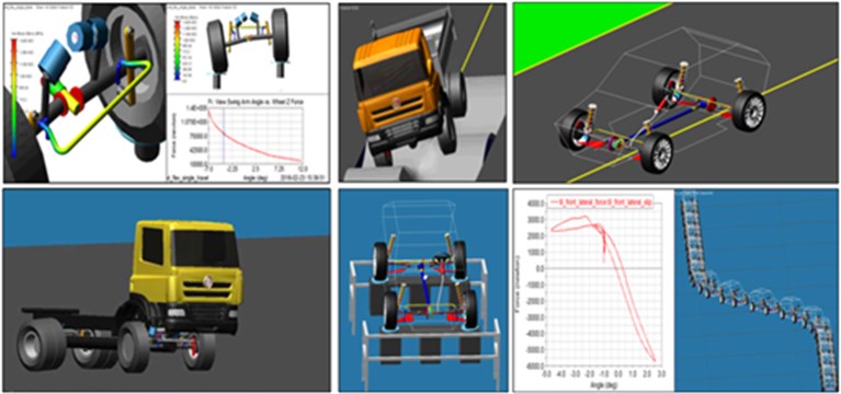
Through the multibody method of mechanism analysis, it is possible to perform static, kinematic and dynamic simulations of individual subsystems and the whole vehicle, and thus analyse the resulting properties using the virtual prototype. MSC ADAMS Car software is the worlds most widely used solution in the field of linking multibody system and the vehicles dynamics theory. Models using this system, however, require numerous input parameters and interdisciplinary experience. Based on the sophisticated databases of the already verified models of individual subsystems, it is possible to significantly shorten the time needed to build the basic and also more advanced analyses, while achieving sufficient robustness of calculation. For validation of the direct complete vehicle ADAMS model, the combination of measured channels from real vehicle testing and computed channels from SAMS multibody model is used.
Predefined as well as custom test rigs for axles, drivetrain and the entire vehicle are employed to simulate the various events. During driving simulations, it is possible to use a variety of standardized maneuvers and multiple levels of feedback driver algorithm [2]. These allow to find and analyse situations that are at the stability limit of the vehicle. Finished models offer virtual testing and analysis of the impact of the construction changes on the vehicle characteristics. The main benefits of the direct vehicle MB model allow for exploration of multiple “what if” scenarios and sensitivity studies. Moreover, it is possible to simply transmit the model to the industrial partners.
Fig. 1Multibody simulations using ADAMS/Car
3. Data analysis using multibody model of vehicle
In addition to simulations of the vehicle and component testing, test drive of the vehicle is further required. These tests verify the function and mutual co-operation of all subsystems, and also perform a synchronisation of all setting elements – the final setting. For these purposes, it is important to have a means which would simplify the data analysis: either with their effective processing or by providing quantities which are essential for the analysis processes. In many cases, these quantities cannot be measured, or it is very difficult to do so. Therefore, a method and software tools are developed to effectively build a detailed multibody model which could be linked with the measured signals and calculate dynamic states of the vehicle while tested.
This chapter describes the resources which make it possible to enclose the driver – test vehicle – mathematical model into one computational loop. These resources are taken advantage of during test drives to analyse the dynamic behaviour of the vehicle, its subsystems and final optimization of their settings.
Application of this approach requires three types of tools which make the process not only doable but also effective.
First indispensable tool is a measurement system. The system has to be able to provide information about every degree of freedom of the vehicle, be it a record of kinematic quantity or force affecting the motion (acceleration). The group of measured quantities differs based on the modelled automobile. At the IAE-BUT, a special measurement system, based on National Instruments components, was developed.
The other tool is software which allows for analysis of measured data as well as bidirectional connection with the computational model. This software is described in detail further in the paper (see Chapter 4).
The third tool is software for mathematical modeling of the vehicle. Objective is to test and assess design of the vehicle. Therefore, it is necessary for the mathematical model to be at least as detailed as the simulation tool used for its development. Nowadays, very detailed multibody models are used in vehicle dynamics. These models may be developed, for example, by ADAMS software which was discussed before. Multibody software SAMS [3] was developed at IAE-BUT and allows to create models at the same level as commercial software ADAMS, for example. Since SAMS was developed by one of this paper´s authors, it was possible to implement functions into the software which feed the measured data into the computational model.
Based on the 3D topology of the mechanism, the software generates model equations in symbolic form (the programming language C++), generally for solving kinematics, statics and dynamics (direct and inverse problems). Multibody formalism that has been applied is briefly described in the appendix. In order to interconnect the measured data with the computational model, the formalism is adapted and supplemented by modelling elements, allowing the model to include forces and torques of unknown size.
This tool very effectively facilitates development of a vehicle’s detailed model with an arbitrary type of axle. Further, it is very easy to arbitrarily parametrise the model.
The generated code (symbolic equations extended with functions for their calculations) is compiled into a dynamic link library (DLL). The software TeleMatrix works with DLL for data analysis and that’s why the DLL involves functions for bidirectional communication with this software.
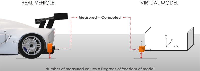
The interconnection of the measured data with the mathematical model is based on a simple notion. Signals from sensors mounted on the vehicle in motion must at every moment correspond with calculated signals from modelled sensors “mounted” on the modelled vehicle (Fig. 2). Inverse mathematical model of the vehicle is extended with the condition for equality of both signals (measured and virtual) and the state of the vehicle which complies with this condition is calculated.
Fig. 2Interconnection of virtual vehicle (model) with data measured at a real vehicle
Based on the calculated state, basically any quantity in the mathematical description of the vehicle may be then calculated. This arrangement provides the automotive engineer with many quantities which are hard to measure yet very useful for analysis of the vehicle’s behaviour, for example, the camber angle measured relatively to the road surface or the forces generated between tires and the road and gather useful characteristics from these quantities.
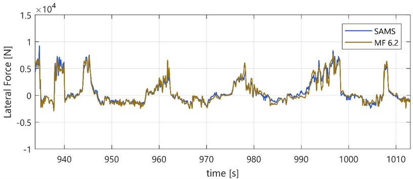
This approach provides several benefits compared to conventional simulations. If the structure of the model and measured quantities is adequate, then there is no need to model some of the vehicle’s parts. This is, of course, unimaginable with the conventional models for simulation computing. Drivetrain is one of the parts that may not have to be modelled, provided that moments and rotation of drive shaft are measured. Other parts that don’t need to be modelled are tires. Parameters of tire models may be adjusted for various road surfaces using kinematic quantities and forces calculated from vehicle dynamics. What is more, the measured quantities may even help to identify those parameters. Fig. 3 displays comparison of lateral forces calculated in SAMS from dynamics of a vehicle in motion, and forces calculated from Magic Formula 6.2 tyre model [4] with parameters from laboratory measuring. Measurement and parameters fitting process were performed by TASS International. Tire lateral forces were calculated by vehicle model where input signals were measured during ride on test track.
All quantities important for reconstruction of motion calculated from the multibody model are acquired by the vehicle itself during the ride, which is another advantage, compared to conventional simulation. This configuration allows for basically immediate reconstruction of the vehicle’s states after the vehicle stopped. In contrast to that, an accurate simulation would require tedious preparatory work. That’s why the conventional simulations are predominantly used for calculation of short moves, and only under simplified conditions, such as steady-state circular test or lateral transient response tests (step, sinusoidal or pulse steering wheel input).
The presented method is also very useful for professional racing. Conventional ride simulations of a racing car on closed, relatively short circuits are intensely studied. The simulation is as accurate as detailed is the description of the racing circuit, including tilts, bumps, and friction coefficients. Such a simulation requires a lot of work. Further, adaptation of tyre model parameters must be done, and the most accurate model of aerodynamics and the driver must be developed. This amount of work limits the simulations to predominantly circuit applications. Conventional simulations cannot effectively be used to describe behaviour of a vehicle in rallyes due to the length and variety of the track (among other issues).
Fig. 3Comparison of lateral forces calculated in SAMS from a vehicle’s ride and forces calculated from Magic Formula 6.2 tyre model
4. Data analysis – TeleMatrix
TeleMatrix [5], which is an extension to MATLAB, helps interconnect the above discussed simulations and computations. The main purpose of TeleMatrix is to concentrate and interconnect various analytical tools that can then be easily and quickly applied in the analysis and processing of heterogeneous data. The program also allows to create math channels, scripts and automated procedures, which can then be advantageously applied during all developmental stages of the vehicle. It is important for comparison of the results, e.g. from partial developmental stages – the pre-prototype simulation, verification measurements of the prototype, or test drives during the final tuning of the vehicle. In addition to the wide range of traditional tools for data analysis and the ability to import it from many different formats and data loggers, the program also allows to work with events, commentaries, intelligent search of conditions, compiling final reports, and an overall management of large projects.
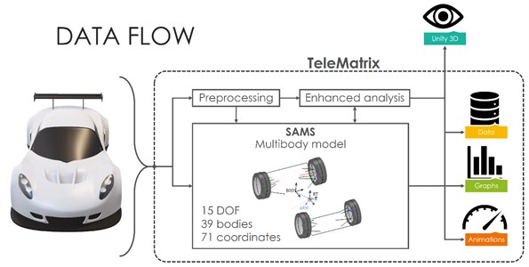
Fig. 4 displays ways to process measured data using SAMS multibody co-simulation. TeleMatrix is responsible for complete project data management as well as for data analysis, filtration, distribution into particular parts of the computational model, and for final visualization. Visualization may be done using integrated tools or external programs, such as 3D engine Unity.
Fig. 4Processing and visualization of data in TeleMatrix
5. Conclusions
A sophisticated combination of commercial and custom-made tools for development and testing of vehicle dynamics and mechatronic systems is described in this article.
For the simulation of a vehicle drive and parameter sensitivity studies, MSC ADAMS/Car software is used.
To reconstruction of whole dynamic states of real vehicle from measured data, the own multibody system SAMS is used. It utilizes an inverse dynamic model and allows to compute an unknown force and other parameters of vehicle.
Complex assessment and comparison of data from all individual stages of the project are then performed by TeleMatrix program which includes a number of integrated general and also specialized tools.
References
-
Blundel M., Harty D. The Multibody Systems Approach to Vehicle Dynamics. Elsevier Buterworth-Heinemann, Oxford, 2004.
-
Fojtášek J. Lane change maneuver of virtual heavy vehicle equipped with yaw moment control. Perners’ Contacts, Vol. 11, Issue 4, 2016, p. 24-31.
-
Porteš P. Utilisation of Mathematical Vehicle Models in Analysis of Measured Data. Habilitation Thesis, Brno University of Technology, 2014, (in Czech).
-
Pacejka H. B. Tire and Vehicle Dynamics. Elsevier Ltd., Oxford, 2012.
-
Zháňal L., Porteš P. Universal tool for data analysis. Perners’ Contacts, Vol. 11, Issue 4, 2016, p. 136-143.
About this article

The research leading to these results has received funding from the MEYS under National Sustainability Programme I (Project LO1202) and Specific Research Project of the Faculty of Mechanical Engineering, Brno University of Technology (FSI-S-17-4104).
