Abstract
In this work the experimental researches of dynamics of a model of a chain-type two-mass oscillatory system with two unbalance vibration exciters are carried out. The method of smooth variation of the debalances speed is used to analyze the amplitude-frequency response of the model. The modes of synchronous rotation of debalances are studied depending on the control parameter – the frequency of the supply voltage. The power characteristics of the electric drive and the influence of the carrying body oscillations on the power consumed by the exciter are established. It is shown that the effect of adaptive self-synchronization of debalances occur in the mechanical system, when the oscillation modes of carrying body vary with the excitation frequency.
1. Introduction
In this paper the oscillations of experimental model of a chain-type two-mass oscillatory system are studied. The vibration is excited by two unbalance exciters driven by asynchronous electric motors. Such a dynamic scheme of the model, in particular, imitates one of the possible schemes of vibrating machines used for crushing, classification, transporting etc. [1-7]. The necessity of the study is related to absence in the existing literature of data on the instability of the self-synchronization forms of unbalance exciters in a wide range of excitation frequencies. Note that when developing such type of vibrating machines, as a rule, the issue of their stable operation at a predetermined excitation frequency, usually at a pre-resonant or beyond-resonant frequency, is investigated [1, 4, 7, 8]. For machines with automatic control systems for vibration modes, and in particular resonance machines, it is of considerable interest to analyze synchronous motion regimes in resonant regions in which, due to the occurrence of finite displacements and nonstationary nature of the technological load, the nonlinear features of the system behavior are appeared to the greatest degree [3, 5, 8-11].
To reveal main features of the dynamic processes occurring in a two-mass mechanical system with self-synchronizing exciters in a wide range of excitation frequencies, the results of experimental studies of the model's oscillations at different rotational speeds of the debalances are described in the present article. Control of their speed is provided by changing the frequency of the supply voltage supplied through the inverter to the winding of the asynchronous electric motors with a squirrel-cage rotor.
2. Experimental model
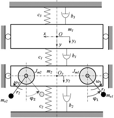
The experimental model, Fig. 1, is made in the form of a chain-type two-mass system, with movable upper weight 1 of mass m1= 2.63 kg, simulating the working body of a vibrating machine including a technological load, and a lower weight 2 of mass m2= 4.57 kg. Two motor-vibrators 3 of an asynchronous type are rigidly attached to the lower weight, symmetrically about the vertical axis Oy passing through its center of mass. The weights are connected to each other by a coil spring 4, the weight 2 is connected to the rigid frame 5 by means of two same springs 6, and the weight 1 is connected to the rigid frame 5 by means of two leaf springs 7. Each of the weights is equipped with ball rolling bushings 8 on the edges, which are able to move along cylindrical rail guides 9 fixed parallel to each other on the frame 5. Thus, each of the weights can move only in the vertical direction along the axis Oy in parallel with the longitudinal axes of the cylindrical guides. Each motor-vibrator has two pairs of poles, i.e. the frequency of its rotation at idling is half of the supply voltage frequency. Both motor-vibrators are powered by a single inverter, which allows to regulate the frequency of the debalances rotation by changing the frequency of the supply voltage. At the same time, the connection of the motor-vibrators to the power supply is carried out in such a way that when the supply voltage is applied, the debalances rotates in opposite directions towards each other. So, the experimental model corresponds to the design scheme of vibrating machines shown in Fig. 2.
Fig. 1Experimental model
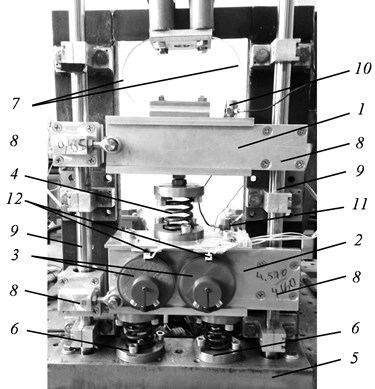
Fig. 2Design scheme
3. Measuring system
Oscillations of the model are measured by two piezoelectric accelerometers 10 and 11 (Fig. 1), rigidly attached to the weights. Optical encoders 12, generating an electrical impulse at the upper position of debalance are used for measuring the rotational speed of each debalance. The electric power consumed by the electric drive is measured by a wattmeter at the site of connection of the inverter to the power supply net. Stroboscopic lighting is used to visualize both oscillations modes and relative position of the rotating debalances.
4. Experimental technique
The testing procedure is in determining the amplitude-frequency response of the system from vibration signals measured by accelerometers, estimating power consumption depending on the excitation frequency by the wattmeter, and establishing the relationship between the power supply frequency and the speed of rotation of the debalances. Determination of these characteristics was carried out with a slow stepwise increase in the power supply frequency (acceleration), and, accordingly, the speed of rotation of the debalances in the range from 10 rot/s to 35 r/s. In order to identify possible non-linearities of the system, the investigation of these characteristics was also carried out with a decrease in the speed of the debalances (run-out), i.e. when first they were accelerated to a frequency of 35 rot/s and then the frequency slowly decreased. The rate of change in the rotational speed was set so that it did not affect the amplitudes of the resonance oscillations. Comparison of the phases of oscillations measured by piezoelectric accelerometers makes it possible to reveal the forms of the system oscillation. All the accelerometers were calibrated so that for a given acceleration of the vibro-calibrator their readings were in-phase and identical in amplitude values.
In accordance with the chosen technique of experimental determination of the dynamic characteristics, a virtual instrument was created in the LabVIEW software package, allowing for a given program to increase (or decrease) the frequency of the voltage applied to the motors, record the measured signals, process them – determine the amplitudes and frequencies of oscillations, debalances rotational speed, to obtain frequency response. All the results of measurements and signal processing were generated into the corresponding numerical arrays and graphic files with the output of the latter on the PC screen.
5. Analysis of the model oscillation
Fig. 3 shows frequency responses obtained at measuring oscillation of the upper weight (curve 1) and the lower weight (curve 2) at slow increase (Fig. 3(a)) and decrease (Fig 3(b)) in the debalances rotational frequency. One can see that there are two resonance frequencies at 13,7 and 27,5 Hz. Moreover, during acceleration, an apparent disruption of the oscillation amplitudes and a sharp change in the oscillation frequency after passing through the resonant frequencies are observed. Note that during acceleration and run-out the resonant frequencies are practically the same, but the amplitudes of the resonance oscillations differ significantly.
Fig. 3Frequency response of the weights at: a) increase, b) decrease of the power supply frequency: curve 1 – upper weight, curve 2 – lower weight
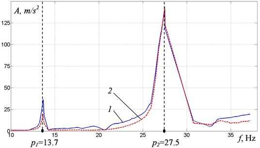
a)
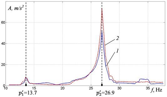
b)
To determine the vibration modes at resonant frequencies, a comparative analysis of the accelerometers signals was carried out. When oscillations are excited at the first resonant frequency, the weights oscillate in phase, while at the second resonant frequency the oscillation form corresponds to the antiphase motion of the weights.
Simultaneously with the determination of the resonant frequencies and modes of the model oscillation, measurements of the debalances rotational speeds were made with the help of encoders. Fig. 4 shows relations between power supply frequency and debalances rotational speed obtained at slow increase (Fig 4(a)) and decrease (Fig. 4(b)) in frequency of the power supply. There are characteristic manifestations of the Sommerfeld effect in the form of jamming of the rotation frequency with a change in the frequency of power supply in the near-resonance zones, as well as their sharp change when the oscillations are disrupted.
Fig. 4Frequency n of debalances rotation at: a) slow increase, b) decrease in frequency of the power supply
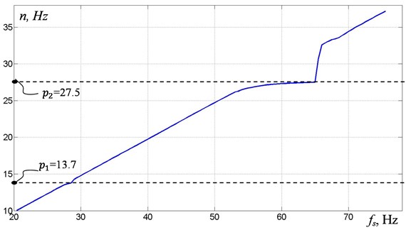
a)
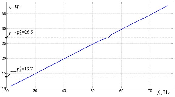
b)
Additional observation of the debalances relative position in stroboscopic illumination has shown that the disruption of oscillations during the transition through resonant frequencies is accompanied by a sharp change in both the mutual phasing of the debalances and the frequency of their rotation. Note that as the power supply frequency was increased, a stable form of synchronization of the debalances was observed in the frequency range from 25 Hz, while the phase shift was determined by the shape of the system oscillations. Near the first and second resonances, the phase shift was established near 0°, when the second resonance was disrupted, the value of the phase shift was established near 180°. With a decrease in the power supply frequency near the second resonance a periodic change in the phase shift near 180° was observed, which was caused by the occurrence of beats. After disruption of the oscillations, the value of the phase shift was established near 0°.
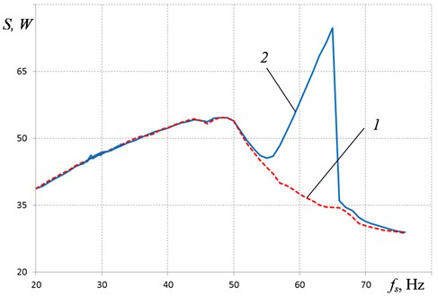
Fig. 5 shows the results of measuring the power S consumed by the electric drive with increasing frequency of the supply voltage. Curve 1 corresponds to the characteristic of the power consumed by the electric drive when installing unbalance exciters on a stationary base, curve 2 – when exciting oscillations of the model. It can be seen that significant increase in the power consumption occurs only near the second resonance of the system. In the rest of the frequency range, no significant increase in power is observed, which indicates a relatively small friction in the system.
Fig. 5Consumed power S
6. Conclusions
The experimental researches have shown that, despite the linearity of the elastic system, the signs of a nonlinear system that are due to the non-ideality of the moment characteristics of asynchronous motors of unbalance exciters clearly appear in its oscillations. The change in frequency of the debalances synchronous rotation leads to the appearance of various forms of vibration of the carrying body, which in turn leads to a different mutual phase shift of the debalances. The described features of the two-mass system dynamics should be taken into account when developing control systems for its oscillations.
References
-
Blekhman I. I. Theory of vibration processes and devices. Vibration Mechanics and Vibration Technology. ID “Ruda and Metally”, St. Peterburg, 2013.
-
Blekhman I. I. Vibrational Mechanics. Nonlinear Dynamic Effects, General Approach, Applications. World Scientific, Singapore, 2000.
-
Lavendel E. E. Vibratsii v tekhnike: Spravochnik v 6-ti tomakh (Vibrations in Engineering. Handbook in 6 Vols.), Vol. 4: Vibratsionnye protsessy i mashiny (Vibration Processes and Machines). Mashinostroenie, Moscow, 1981, (in Russian).
-
Vaisberg L. A., Zarogatsky L. P., Turkin V. Vibratory crushers. Fundamentals of calculation, design and technological application. Izdatelstvo VSEGEI, St. Peterburg, 2004, (in Russian).
-
Shishkin E. V., Kazakov S. V. Vibratory crusher forced oscillations in resonance frequency range. Mineral Processing, Vol. 5, 2015, p. 42-45, (in Russian).
-
Antipov V. I., Palashova I. V. Dynamics of a two-mass parametrically excited vibration machine. Journal of Machinery Manufacture and Reliability, Vol. 39, Issue 3, 2010, p. 238-243.
-
Li Xiaohao, Shen Tao. Dynamic performance analysis of nonlinear anti‑resonance vibrating machine with the fluctuation of material mass. Journal of Vibroengineering, Vol. 18, Issue 2, 2016, p. 978-988.
-
Blekhman I. I. Synchronization of Dynamical Systems. Nauka, Moscow, 1971.
-
Panovko G. Y., Shokhin A. E., Eremeikin S. A. Experimental analysis of the oscillations of a mechanical system with self-synchronized inertial vibration exciters. Journal of Machinery Manufacture and Reliability, Vol. 44, Issue 6, 2015, p. 492-496.
-
Panovko G., Shokhin A., Eremeykin S., Gorbunov A. Comparative analysis of two control algorithms of resonant oscillations of the vibration machine driven by an asynchronous AC motor. Journal of Vibroengineering, Vol. 17, Issue 4, 2015, p. 1903-1911.
-
Eremeikin S. A., Krestnikovskii K. V., Panovko Ya G., Shokhin A. E. Experimental analysis of the operability of a system to control the oscillations of a mechanical system with self-synchronizing vibration exciters. Journal of Machinery Manufacture and Reliability, Vol. 45, Issue 6, 2016, p. 553-558.
About this article

The research was supported by Russian Science Foundation (Project No. 18-19-00708).
