Abstract
To more realistically describe the operation of an eddy current brake under intensive impact load, a magnetic-thermal bidirectional coupling model of the eddy current brake is established considering the existence of temperature. The variation of material and convective heat transfer coefficient with temperature are considered in the model. The iterative method is used to decouple the model. Through the analysis of the numerical simulation results, the temperature distribution and transmission of the brake during operation are obtained. By comparison, it is found that the calculated braking force of the magneto-thermal coupling model is lower than the calculated value without considering the temperature field due to the influence of temperature. And the higher the temperature, the greater the decrease.
Highlights
- A magnetic-thermal bidirectional coupling model of the eddy current brake is established.
- The temperature rise of permanent magnets is not large.
- The temperature peak on the inner cylinder reaches 340K.
- The braking force drops when the temperature field is taken into account.
1. Introduction
According to electromagnetic induction theorem, eddy currents are caused due to relative motion of the field source and conductor. They create magnetic fields and cause a repulsive force proportional to the relative velocity of the field and conductor [1].
The eddy current brake is a new type of brake device designed based on the above principle. Eddy current brakes are divided into electromagnetic brakes, permanent magnet brakes and hybrid brakes depending on the excitation source. Compared with electromagnetic brakes and hybrid brakes, permanent magnet brakes do not require external excitation power supply and excitation winding. They save electricity and copper usage, reduce the size of the device, and simplify the structure of the device. On the other hand, their reliability is higher because there is no danger of brake failure during power failure [2-4].
The braking characteristics of permanent magnet linear eddy current brakes have been studied by domestic and foreign scholars. Bae et al. [5] obtained a mathematical model of the eddy current braking force according to Biosal’s law and Lorentz force formula. However, they ignored the effects of armature reaction and skin effect at high speed. Chen et al. [6, 7] derived the damping coefficient of the plane type eddy current brake, and explored the influence of each design parameter on the brake according to theoretical derivation and experiments. Yin [8] applied the theory of hierarchies to deduce the magnetic vector potential and introduced the demagnetization coefficient to consider the demagnetization effect.
At present, the research on permanent magnet linear eddy current brakes is focus on the case of low-speed steady state. However, the response to transient impact loads under extremely severe working conditions is less studied. From the perspective of energy conversion, the mechanical energy of the moving parts is firstly converted into electrical energy on the conductive material, and then converted into heat energy by the electric resistance during the operation of the eddy current brake. Transient impact loads are often accompanied by large kinetic energy, which will eventually generate heat in a relatively closed space. Therefore, considering magnetic field and temperature field during operation will be closer to the real situation [9, 10].
This paper establishes a magneto-thermal dynamics model of the eddy current brake. The braking force of the eddy current brake under intensive impact load are analyzed according to the numerical simulation results. The role of the temperature field in the operation of the eddy current brake is demonstrated by the comparison with a dynamic model with only magnetic fields.
2. Magneto-thermal coupling dynamics model of the eddy current brake
2.1. Mesh division of the eddy current brake
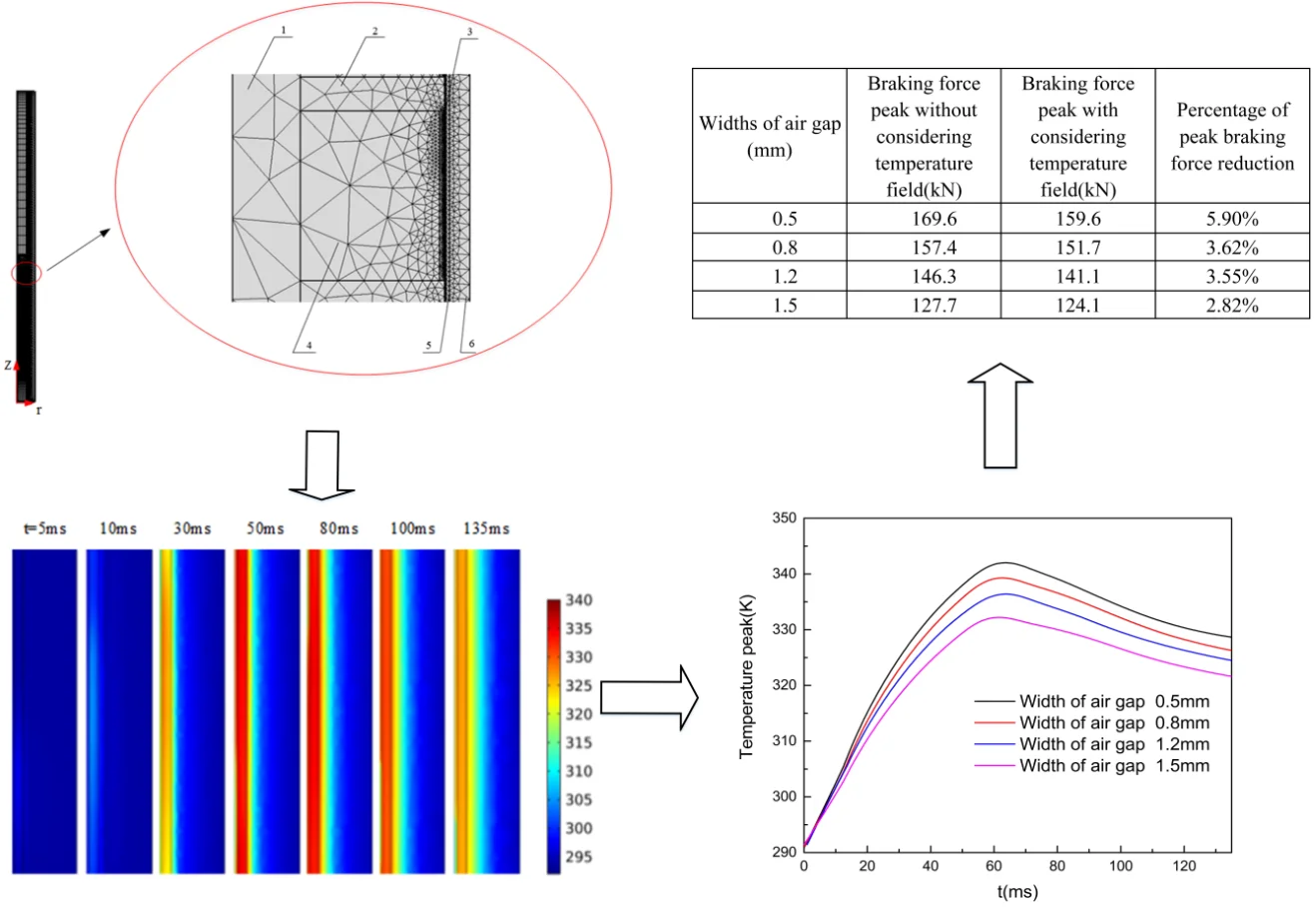
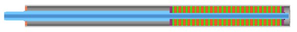
As Fig. 1 shows, the eddy current brake is divided by using the two-dimensional axisymmetric analysis method of AC/DC module in COMSOL. The eddy current brake includes primary: magnetic shoes, permanent magnets, the moving rod, secondary: the outer cylinder, the inner cylinder and the end cover. The primary moves under the impact load and the secondary is stationary when the eddy current brake is in operation. The relative motion between the primary and secondary will induce eddy currents on the inner cylinder. According to Lenz’s law, the magnetic flux generated by the eddy current will interact with the primary magnetic flux and then braking force is generated.
Fig. 1Structure diagram and mesh diagram of the eddy current brake
a)
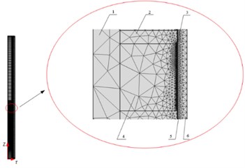
b) 1 – the moving rod; 2 – magnetic shoes; 3 – air gap; 4 – permanent magnets; 5 – the inner cylinder; 6 – the outer cylinder
2.2. Physical properties of the material
The magneto-thermal coupling has two forms: unidirectional coupling and bidirectional coupling. Unidirectional coupling makes the results of electromagnetic field analysis the initial conditions for thermal analysis. Thermal analysis does not affect the results of magnetic field analysis. Bidirectional coupling analysis is based on the data exchange of magnetic field and temperature field. When calculating in this way, the temperature field will affect the calculation of the magnetic field by affecting the magnetic properties of the material. In the bidirectional coupling model of this paper, the effects of temperature on the remanence of permanent magnets and the conductivity of the inner cylinder are considered.
(1) The effects of temperature on the remanence of permanent magnets.
In the permanent magnet eddy current brake, the strength of the magnetic field provided by the permanent magnets plays a decisive role in the magnitude of the braking force.
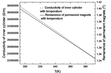
The permanent magnet used in this simulation is M-type sintered NdFeB. According to GB/T 13560, the relationship between remanence and temperature of NdFeB is shown in Fig. 2. Remanence is input to the simulation model in the form of a fitting function as follows:
(2) The effects of temperature on the conductivity of the inner cylinder
The inner cylinder is the carrier that generates eddy currents. When the temperature rises, the conductivity of the inner cylinder decreases. This will directly lead to a decrease in the braking force. Conductivity is also input to the simulation model in the form of a fitting function as follows:
Fig. 2Curve of inner cylinder conductivity and permanent magnet remanence with temperature
2.3. Temperature field physical model of eddy current brake
The three-dimensional heat transfer differential equation of temperature field is established according to the first law of thermodynamics and Fourier’s law:
where , , , and are the brake’s thermal conductivity, specific heat capacity, density time and, heat flow per unit time and volume, respectively.
During the temperature transmission of the linear eddy current brake, only heat conduction and convection are considered and the influence of radiation is ignored due to the limited temperature rise. The specific transmission process is shown in Fig. 3.
The convective of the inner cylinder to the air gap and the outer cylinder to the outside air is represented by the third type of boundary condition of the temperature field.
The inner and outer boundary condition are:
where , , , and are the temperature of the inner cylinder, the outer cylinder, the air gap and the external air, respectively. , are convective heat transfer coefficient of inner and outer boundary.
According to experimental research, the following formula can be used to express the convective heat transfer coefficient [11]:
where subscript means that the qualitative temperature is the membrane temperature. The membrane temperature is calculated as follows:
where and are the temperature of air and surface, respectively.
and are the Grachev and Prandtl numbers. According to the literature, the coefficient 0, 0.53, and the index 0.25:
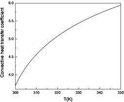
The thermal conductivity , viscosity , and expansion coefficient of air are defined as a function of temperature. The relationship between the convective heat transfer coefficient and temperature is shown in Fig. 4.
Fig. 3The route of temperature transfer
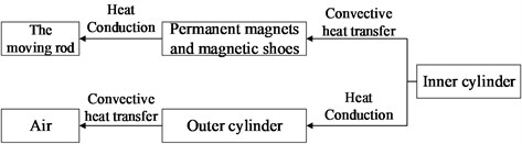
Fig. 4Curve of convective heat transfer coefficient with temperature
3. Simulation results and analysis of magneto-thermal coupling model
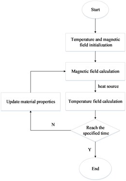
The intensive impact load shown in Fig. 5 is loaded into the magneto-thermal coupling model and then the model is solved by the distribution iteration method. The solution flow is shown in Fig. 6.
Fig. 5Curve of the intensive impact load
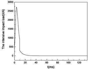
Fig. 6Flowchart of the distributed iterative computation
3.1. Temperature distribution of the eddy current brake in working process
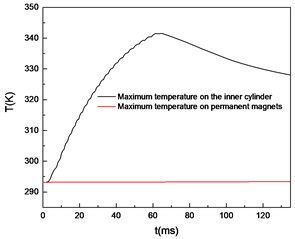
It can be seen from Fig. 7 and Fig. 8 that the heat source is mainly generated in the inner cylinder and diffuses from the inner cylinder to both sides. The temperature on the inner cylinder is higher during the 50-80 ms period and the temperature peak reaches 340 K. After that, the temperature gradually expands to the outer cylinder region and the air gap layer. Due to the presence of the air gap layer, the temperature is not excessively transmitted to the permanent magnet region and the temperature rise of permanent magnets is not large.
Fig. 7Contour of temperature distribution over time
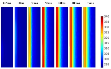
Fig. 8Curves of maximum temperature over time
3.2. Effect of temperature field on magnetic field
By comparing two pictures in Fig. 9, it is found that there is a difference in the calculation results between the simulation models with and without considering the temperature field. The braking force is smaller when the temperature field is taken into account. Table 1 lists the percentage of peak braking force reduction with different widths of air gap.
Fig. 9Braking force characteristics with widths of air gap uncoupled a) and coupled b) temperature field
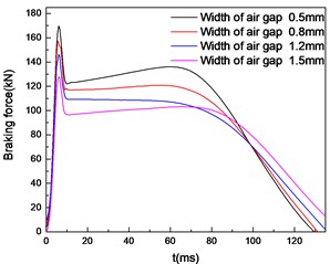
a)
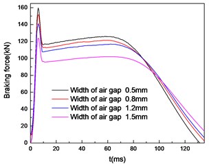
b)
Fig. 10Temperature peak of the brake with widths of air gap
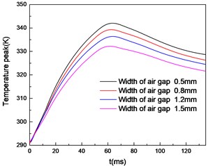
It can be found that the smaller the air gap width is, the greater the percentage of braking force reduction caused by temperature field is. This is because when the width of air gap decreases, the temperature increases as Fig. 10 shows. The weakening effect of temperature on braking force increases. So it is necessary to pay attention to heat dissipation while ensuring the magnitude of the braking force. This can avoid excessive influence on the braking performance of the brake.
Table 1Comparison of braking force peaks with or without temperature field
Widths of air gap (mm) | Braking force peak without considering temperature field (kN) | Braking force peak with considering temperature field (kN) | Percentage of peak braking force reduction |
0.5 | 169.6 | 159.6 | 5.90 % |
0.8 | 157.4 | 151.7 | 3.62 % |
1.2 | 146.3 | 141.1 | 3.55 % |
1.5 | 127.7 | 124.1 | 2.82 % |
4. Conclusions
In this paper, the magneto-thermal coupling model of the eddy current damper is established, the temperature distribution in the working process of the eddy current brake is explored, and the influence of the temperature field on the braking force is analyzed. The research results show that:
1) During the operation of the eddy current brake, the heat source is mainly generated in the inner cylinder region, and the temperature of the inner cylinder rises rapidly. At about 65 ms, the inner cylinder temperature reaches 340 K, and the temperature rise of the permanent magnet portion is not large. Therefore, the temperature field mainly changes the electrical conductivity of the inner cylinder and thus affects the braking force.
2) By comparing the simulation results of coupled temperature field and uncoupled temperature field under different air gap width, it is found that the smaller the air gap width is, the greater the braking force is; meanwhile, the higher the temperature rise in the magneto-thermal coupling model, the greater the weakening effect of temperature on the braking force is.
References
-
Kou Bao-Quan, Jin Yin-Xi, Zhang He, et al. Development and application prospects of the electromagnetic damper. Proceedings of the CSEE, Vol. 35, Issue 12, 2015, p. 3132-3143.
-
Graves Ryan Effects of Magnetic Material on Performance of Permanent Magnet Synchronous Machines. Master Thesis, The University of Alabama, 2014.
-
Tang Yong-Chun, Ye Yun-Yue Analysis of permanent magnet eddy-current brake with finite element method. Micromotors, Vol. 3, 2006, p. 34-36.
-
Niu Hua Wei, Chen Zheng Qing, et al. Mitigation of wind-induced vibrations of bridge hangers using tuned mass dampers with eddy current damping. Smart Structures and Systems, Vol. 22, Issue 6, 2018, p. 727-741.
-
Bae J., Hwang J., Park J., et al. Modeling and experiments on eddy current damping caused by a permanent magnet in a conductive tube. Journal of Mechanical Science and Technology, Vol. 23, Issue 11, 2009, p. 3024-3035.
-
Chen Zheng-Qing, Zhang Hong-Yi, Huang Zhi-Wen FEM simulation and parameter optimization of a planar eddy current damper. Journal of Vibration and Shock, Vol. 35, Issue 18, 2016, p. 123-127.
-
Chen Zhengqing, Tian Jing-Ying, Huang Zhi-Wen, Wang Jian-Hui Calculation and test correction method of plane type eddy current damping coefficient. China Journal of Highway and Transport, Vol. 29, Issue 10, 2016, p. 46-53.
-
Yin Xiang-Rui Research on long stroke secondary moving permanent magnetic linear eddy current brake. Harbin Institute of Technology, 2017, p. 10-19.
-
Chen Tao, Yan Ye-Cui, Ma Qi-Hua, Zhang Lu-Lu Research on magneto-thermal coupled methodology of in-wheel motor. Light Industry Machinery, Vol. 36, Issue 5, 2018, p. 57-62.
-
Ye Le-Zhi, Li De-Sheng Demagnetization characteristic analysis of permanent magnet retarder in high temperature. Mechanical Science and Technology for Aerospace Engineering, Vol. 29, Issue 5, 2010, p. 566-569.
-
Yang Shi-Ming, Tao Wen-Quan Heat Transfer. 4th ed., Higher Education Press, Beijing, 2006, p. 211-252.
About this article

