Abstract
This paper describes several key aspects about multi-axis sine vibration test control techniques including the identification of the system frequency response function, synchronization of the input and output signals, the generation of the sinewave, the control algorithm, etc. A multi-axis sine vibration controller is developed based on these key techniques and the major framework of the controller is introduced. Finally, a dual axial experiment is carried out by the controller. The test results show the feasibility of the control algorithm and the good control strategy of the multi-axis sine vibration controller in which the key techniques are realized.
1. Background
The spacecraft experiences complicated vibration environments during it launch, flight and re-entry stage. These vibration environments would affect the structure of the spacecraft or the equipment through the dynamic transfer process, and sometimes result in the damage of the structure, the degradation of the equipment function and malfunction.
Based on the influence of these vibration environments to the structure or the equipment of spacecraft, it is necessary to reproduce those environments experienced by the spacecraft to ensure the successful launch and normal function of the spacecraft during its life period.
In vibration testing, it is common that the test level requirements are specified as an acceleration level spectrum that needs to be reproduced at a certain control location. Such a test is typically performed in a single-axis setting, where the test article is subjected to vibrations in one direction only. If more than one direction is of interest, consecutive tests are performed after rotating the test article or using a slip table configuration. In the vibration control literature following typical drawbacks of sequential single-axis/single shaker testing reported:
– The time to change the test set-up twice and repeating the control test can be excessive.
– During the set-up changes, the risk of damage of the sometimes very expensive and fragile test articles exist.
– There is definitely some lack of realism in single-axis testing, as the stress loading conditions will differ from the true three-dimensional stress situation.
In some cases it is therefore necessary to subject the test article to a three-dimensional, six degrees of freedom (DOF) vibration environment. A multi-axis/ multi-shaker configuration has the following benefits:
– A highly realistic vibration environment is achieved during the qualification test. The fatigue failure predictions from such a test will be very accurate.
– All structural modes are simultaneously excited. The qualification test data could be used for a complete modal analysis of the structure.
– For very heavy structures, often the excitation level from a single shaker is not sufficient. For very slender structures, a single shaker could damage the structure due to concentrated stresses. In both situations it is desirable to use multiple shakers to provide sufficient or distributed forces [1-6].
In order to reproduce those multi-axis vibration environments, the most important step is to obtain a multi-axis vibration controller which mainly includes multiple exciter applications, such as multi-axis swept sine, random, shock and replication etc. In the following of this paper, we will introduce some key techniques in detail for the development of the multi-axis swept sine vibration controller. Then a dual-axial experiment is carried out by the multi-axis shaker and controller. Finally, the test results are analyzed and the feasibility of the control algorithm is verified.
2. The multi-axis sine control techniques
2.1. System identification
The first step to solve a multi-axis control problem is to identify the system transfer function matrix . For this purpose, n independent low level random signals are injected into the system and the system’s responses are measured. Then the transfer function matrix can be determined as following:
where:
is the auto-spectrum of input signals, which is invertible due to the independence of the input signals, and:
is the cross-spectrum of the response signals and the input signals. Other approaches to system identification have been tested, such as exciting one shaker at a time using a random signal or a swept sine signal. These two approaches require much longer time but do not provide better results [7].
2.2. Signal synchronization
The synchronization of the input response signal and output drive signal is an important technique in the development of the multi-axis vibration controllers. For multiple A/D converter boards, signal synchronization is able to ensure the consistency of all measurement channels. While for A/D and D/A converter boards, this technique is to ensure the accuracy of the system transfer function matrix measurements between the input response signals and output drive signals.
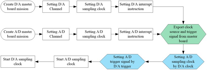
For the PXI A/D or D/A converter boards, the master board and slave board need to be defined before signal synchronization. The sampling clock source and triggering signal exported from the master board are applied to the slave’s board. The clock of all slave boards shall be activated before the master board to ensure the normal function of signal synchronization. Fig. 1 shows the flow chart of the signal synchronization between PXI converter boards.
2.3. Drive signal generation
However, in order to have satisfied phase control, the sine wave generation needs to be accurate, fast and smooth for any combination of amplitude, frequency and phase. Sinewave generation can be accomplished either by the control system computer and a software algorithm or by special dedicated computer-controlled hardware such as a programmable function generator [8].
Fig. 1Flow-chart of signal synchronization for PXI boards
The software generation can be implemented in the following manner. Assume an allocation of core locations to store N values of a complete sine function (0 to 2 radians). The sine values can be generated and stored in these allocated core locations by performing the following integer arithmetic:
where 1, 2, 3,…, , and is the number of points of a complete single-period sineware. If all points have been sent out through D/A converter at a clock rate of , then a sinewave will be generated with a frequency of according to the following equation:
In order to increase the frequency in accord with the above equation, it is necessary to output the sine values in the allocated core locations at a faster rate, and if the clock that works the digital-to-analog (D/A) converter operates at a constant rate, fewer values must be put out as the frequencies increases. This means that the software algorithm will pick up the values from the sinewave table at a faster rate. For the generation of two sinewave signal with the phase difference of , then the number of points that one sinewave signal must overtake the other signal can be determined as following:
Generally, the time that the overtake process spend is within one fifth period of the current excitation signal to ensure the smooth and stable transition. The pick-up points sent out by the D/A converter is passed through a low-pass filter to guarantee that even a very minimum number of values will yield a clean sinewave of low distortion.
2.4. Loop control algorithm
The reference spectrum for the multi-axis sine vibration control is specified by the magnitude spectrum and phase spectrum in the frequency domain:
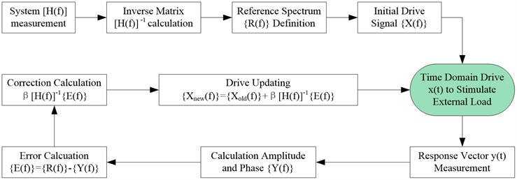
The loop control algorithm’s mission is to find the appropriate drive signal to ensure the response vector meet the requirements of the reference vector. The drive signal vector can be determined according to the following equation:
Because of the existence of nonlinearity and system error, we don’t expect the drive signals computed according to the above equation can produce the exact response that we need. So, the loop control is needed to update the drive signal in a real time during the test process. The drive signal can be updated according to the following equation group [9]:
Fig. 2Flow-chart of the multi-axis sine vibration control algorithm
3. Test setup and validation
3.1. Test system introduction
It is shown in Fig. 3 that the triaxial vibration test system consists of three shakers, hydrostatic bearings, platform, power amplifiers, controller etc. Each shaker’s thrust force is 60 kN. The size of the platform is 600 mm×600 mm. The working frequency for this system is from 5 Hz to 2000 Hz.
Fig. 3Triaxial vibration test system
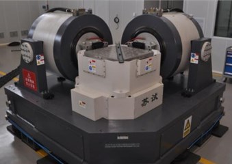
Fig. 4Multi-axis sine vibration controller
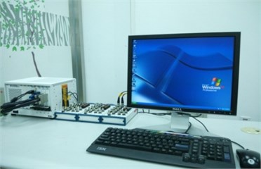
By using the above critical sine control techniques, BISEE has successfully developed a multi-axis sine vibration control system, consisting of A/D and D/A converter boards, PXI host and control software etc. This control system incorporates sixteen A/D channels which acquire the system responses from accelerometers and eight D/A channels which send the drive signal to the shakers.
3.2. The reference for the test
Table 1The reference for the dual-axis sine vibration test
-Axis | -Axis | |
5-8 Hz | 4.65 mm | 6.98 mm |
8-200 Hz | 0.6 g | 0.9 g |
Phase | 0° | 90° |
Sweeping rate | 2 Oct/min | |
3.3. Test and analysis
The multi-axis sine control techniques outlined in previous sections are implemented in the new multi-axis vibration control software under Windows XP. The drives are generated and the control and measurement channels measured using PXI hardware. In order to verify the performance of the implementation, a real-life dual-axis sine vibration control experiment was carried out using a triaxial vibration test system.
Fig. 5X Axis magnitude control spectrum
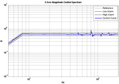
Fig. 6Y axis magnitude control spectrum
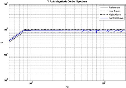
Fig. 7X axis phase control spectrum
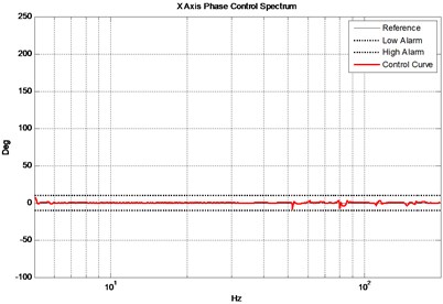
Fig. 8Y axis phase control spectrum
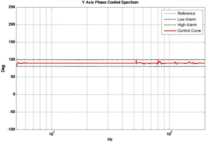
It is now the task of the multi-axis sine control algorithm to find suitable excitation signals that generated the desired responses. The reference at the 3 control locations are shown in Table 1. Fig. 5 and Fig. 6 show the actual magnitude control results compared to the reference while Fig. 7 and Fig. 8 show the phase control results. Note that most part of the magnitude control curve are well within 10 % alarm tolerances and the phase control curve are well within ±10° alarm tolerances except for several level control points nearly 80 Hz as a result of the platform modes. The test results basically meet the test requirements.
4. Conclusions
This paper presented some key multi-axis sine vibration control techniques. The performance of the techniques was verified by a real-life control experiment using a tri-axial shaker. The multi-axis sine control results were excellent. The test results show the feasibility of the control algorithm and the good control strategy of the multi-axis sine vibration controller in which the key techniques are realized.
References
-
Peeters B., Debille J. MIMO random vibration qualification testing: algorithm and practical experiments. Proceedings of ESTECH, Anaheim, USA, 2002.
-
Keller T., Underwood M. A. An application of MIMO techniques to satellite testing. Proceedings –Institute of Environmental Sciences and Technology, USA, 2001.
-
Underwood M. A. Multi-exciter testing applications: theory and practice. Proceedings – Institute of Environmental Sciences and Technology, Anaheim, CA, 2002, p. 1-10.
-
Underwood Marcos A., Keller Tony Applying coordinate transformations to multi degree of freedom shaker control. Proceedings of the 74th Shock and Vibration Symposium, San Diego, CA., 2003
-
Smallwood D. O. Random vibration testing of a single test item with a multiple input control system. Proceedings of Institute of Environmental Sciences, USA, Dallas, 1982, p. 42-49.
-
Smallwood D. O. Multiple shaker random control with cross coupling. Proceedings of the IES, 1978, p. 341-347.
-
Min Chen, Delbert Wilson R. The new triaxial shock and vibration test system at Hill Air Force Base. Journal of the IEST, Vol. 41, Issue 2, 1998, p. 27-32.
-
Chapman P. Digital Vibration Control Techniques. Jet Propulsion Laboratory California Institute of Technology Pasadena, California, 1974.
-
Fan Shichao, Feng Yaoqi Study on Simulation test technology of dynamics environment of multi-DOF. Spacecraft Environment Engineering, Vol. 23, Issue 1, 2006, p. 23-28.
About this article

