Abstract
Mechanical stress and fracture analysis of the human lumbar intervertebral discs are important in assessing disorders related to lower back pain and ageing. Finite element modelling and simulation approaches assist in easier prediction of the disc behaviour under different load conditions. The causes of mechanical failure and morphological changes still remain partially speculative. The present study addresses the issue by developing a finite element model of an L3-L4 lumbar intervertebral disc subjected to different axial compressive loadings. The morphological deformations and stress concentration regions within the disc are analyzed and reported. A mathematical relation is established to estimate the breaking strength of an L3-L4 intervertebral disc, thus indicating the risk of disc failure based on the applied load.
1. Introduction
The biomechanical analysis of the human body is a challenging area for many researchers. The vertebral column is one among the widely studied sub-systems of the human body for the past six decades. The vertebral column plays an important role in supporting the entire body during sitting, standing, gait and various mechanical activities such as weightlifting, etc. In addition, it plays a major role in providing structural integrity to the entire upper body. One of the most commonly faced disorders among people is lower back pain, irrespective of age. Common lower back disorders include strain, lumbar disc degeneration, sciatica, lumbar spinal stenosis and spondylosis. These disorders are known to induce high amount of mechanical strain in the intervertebral discs (IVD) of the lumbar vertebrae. The causes of mechanical failure of the intervertebral disc still remain partially unclear. As engineers, it is important to address these issues by analyzing the lumbar intervertebral segment behaviour from a mechanical perspective. Researchers have carried out various deformation, stress, strain and fatigue analyses either through experimentation or simulations. Ethical restrictions limit the researchers from carrying an in-depth experimental analysis on actual specimens of the lumbar intervertebral discs. Experimental studies are not entirely reliable due to the variability of different species, depending on factors such as age, gender and size, as well as different experimental conditions. Besides, it is difficult to obtain large quantities of human specimens of intervertebral discs and are rather expensive.
Alternatively, analysis of the human lumbar intervertebral disc is quite commonly carried out using finite element (FE) simulations. FE simulation is a valuable computational tool due to its modification flexibility and reduction in cost and time of analysis. The most challenging step is developing an accurate FE model of the lumbar intervertebral disc. Conventional procedure of developing a model is by geometrical reconstruction of data obtained from CT scans. Several studies determined the deformation of the lumbar vertebrae and reported the degree of disc degeneration as a function of the disc displacements. Unfortunately, one cannot consider the disc displacement as a measure of the pain induced, rather the determination of the induced stress is to be considered.
Casaroli et al. [1] generated an FE model of an ovine lumbar intervertebral disc and tested it for complex loading conditions. The study concluded that flexion is the riskiest load condition and disc failure occurred at axial stresses greater than 10 MPa. It shows scope for the estimation of degree of safety for specific load conditions during activities. Schmidt et al. [2] developed FE models of the L4-L5 intervertebral segments for different grades of disc degenerations and investigated the intradiscal pressures and fiber strains under pure and complex loadings. The estimated results showed that the risk of disc failures majorly depend on the degenerative condition of the intervertebral disc and the intradiscal pressure is highest during compressive loads. Yu et al. [3] presented their study by subjecting specimens of porcine lumbar intervertebral discs under fatigue testing, to investigate their morphological changes. The results reported that the primary morphological changes included the bulging of the nucleus pulposus and also the bulging of the anteroposterior ligaments.
This paper is an attempt to present the essence of mechanical stress analysis approach to the biomechanical evaluation of induced stress in the intervertebral disc under varying axial load conditions. This study establishes a load and stress limit for an L3-L4 spinal segment to predict the probability of disc failure. Section 2 outlines the procedure considered in developing an FE model of the L3-L4 intervertebral disc. Section 3 discusses the stress analysis carried out for different load conditions. It provides a quantitative evaluation of the risk of disc injuries with respect to the stress induced.
2. Modelling and materials
A solid model of the L3-L4 lumbar intervertebral disc is developed by an extensive study of its anatomy. The developed disc model is composed of the nucleus pulposus (NP), annulus fibrosus (AF), annulus matrix (AM) and the cartilaginous endplate (CEP). The geometrical dimensions of the L3-L4 intervertebral disc are discussed elsewhere and borrowed from Zhou et al. [4]. The nucleus pulposus is initially modelled and concentrically surrounded by ten alternating layers of the annulus fibrosus and the annulus matrix i.e., AF1-AF5 and AM1-AM5. Subsequently, the cartilaginous end plates are placed in the superior and inferior surfaces of the disc. The models of the NP, CEP and each AF and AM are developed and assembled together in solid modelling software Solid Edge, as shown in Fig. 1.
Fig. 1FE model of L3-L4 IVD composed of NP, AF, AM and CEP
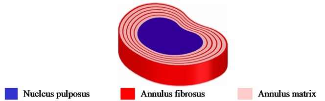
The fully developed disc model is shown in Fig. 1. The material property of each part is considered to be linear elastic; the values are borrowed from literatures and are tabulated in Table 1.
Table 1Material properties of lumbar intervertebral disc
Component | Density, (kg/m3) | Young’s modulus, (MPa) | Poisson’s ratio, | Ref. |
Nucleus pulposus | 1000 | 1 | 0.45 | [5] |
Annulus fibrosus | 1200 | 500 | 0.30 | [6] |
Annulus matrix | 1060 | 4.2 | 0.45 | [6] |
Cartilaginous endplate | 1060 | 24 | 0.40 | [5] |
The developed model is further imported into finite element analysis package Ansys 18.1. The entire model is meshed using adaptive size function. The generated mesh is composed of 4,785 elements and 35,850 nodes. The bottom surface of the disc model is assumed to be fixed as the cartilaginous endplate is rigidly attached to the bony endplate of the L4 vertebra. The load is applied uniformly over the upper surface of the disc i.e., the upper cartilaginous endplate. Torsional loads are not considered for the present study as it primarily affects the posterior elements of the adjacent vertebrae and not the intervertebral disc. No other constraints are provided to the FE model. The results for varying axial loads are evaluated and discussed in the following section.
3. Results and discussion
An axial compressive load is applied uniformly over the entire surface of the top cartilaginous endplate. Ten different load conditions are considered in the range of 100 N to 1000 N with increments of 100 N. The total deformation and equivalent von-Mises stress for each load condition are evaluated and presented. Fig. 2 shows the deformation contours (in mm) of the intervertebral disc under an axial compressive load of 100 N.
Fig. 2Total deformation of the L3-L4 IVD (in mm)
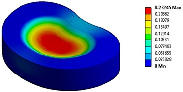
The initial observation made from the analysis is that the maximum deformation of the intervertebral disc occurred at the nucleus pulposus due to its viscous material characteristic. The deformation of the intervertebral disc increased linearly with respect to increase in the applied load. The analysis showed a large amount of fracture failure after the load exceeded a value of 700 N. With deformations related to the annulus fibrosus, the maximum deformation occurred at the posterior fibers due to the curvature of the spinal canal. This indicates that the extreme deformation of the nucleus pulposus leads to a significant increase in the intradiscal pressure, causing the posterior lamellae of the annulus fibrosus to bulge outwards. This bulging of posterior annulus fibrosus induces pressure onto the nerves of the spinal cord, which is a clear indication of the large amount of pain induced. Fig. 3 shows the stress concentration regions and contours of the intervertebral disc under a compressive load of 400 N.
Fig. 3Equivalent von-Mises stress within the L3-L4 annulus fibrosus (in MPa)
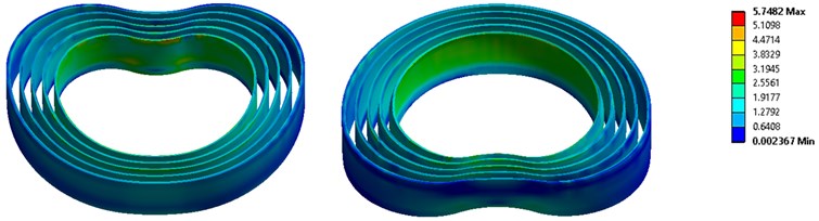
It is observed that the stress distribution throughout the intervertebral disc is not uniform. The primary regions of induced stress are observed at the cartilaginous endplates and the annulus fibrosus. The annulus fibrosus showed a greater amount of induced stress when compared to the cartilaginous endplate. The stresses within the annulus fibrosus increased towards the innermost layers of the fibers. Additionally, the stresses induced in the superior regions of the lamellae are greater and concentrated as compared to the inferior regions. The analysis also showed a higher concentration of stresses at the posterior regions of the annulus fibrosus.
From past studies, it is shown that the annulus fibrosus consist of several nerve endings at the posterior region. The present study proves that the stress concentration due to compressive loads is maximum at the posterior region of the annulus fibrosus. This suggests that the presence of nerve endings at the posterior region is actually the primary source of pain within the intervertebral disc. It is also inferred that the increased intradiscal pressure causes high amount of pain at these nerve endings.
Besides, the stress analysis is carried out for different increasing compressive loads to understand the resulting behaviour. The breaking strength of a component indicates the limit of stress to which it can withstand without any failure. In this present study, compressive loads in the axial direction over the top cartilaginous endplate are applied. The induced stress values are extracted and tabulated in Table 2.
Table 2Equivalent von-Mises stress values for different loads
Load (N) | 100 | 200 | 300 | 400 | 500 | 600 | 700 | 800 | 900 | 1000 |
Stress (MPa) | 1.43 | 2.87 | 4.31 | 5.74 | 7.18 | 8.62 | 10.05 | 11.49 | 12.93 | 14.37 |
The corresponding stress values for each loading are plotted using MATLAB. With reference to previous literatures, the obtained plot is broadly classified into three regions to illustrate the risk associated with disc injury. The stress versus applied load plot is as shown in Fig. 4.
Fig. 4Induced stress vs. load applied, indicating ranges of risk to injury
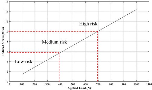
The deformation analysis carried out suggests that an applied load of 700 N and above leads to a significant failure in the posterior region of the intervertebral disc. This indicates that the corresponding stress induced for a load of 700 N is the breaking strength of the intervertebral disc. The L3-L4 intervertebral disc is shown to have a breaking strength of 10 MPa. An induced stress greater than 10 MPa will lead to disc failure. This is also inferred as, an average healthy person carrying an axial load of more than 700 N (approximately 71 kgs) is subjected to high risks of disc failure or fracture. Furthermore, there is no significant deformation observed for applied loads until 400 N. This indicates that, for loads lower than 400 N and a corresponding stress of 5.7 MPa, the probability of failure is low. An average healthy person carrying axial loads below 400 N (approximately 40 kgs) is subjected to low risks of disc injury. A range of load between 400-700 N (i.e., 5.7-10 MPa) is considered to be of medium risk of disc failure. However, the range and probability of disc failure might vary depending on factors such as the present health condition of the intervertebral disc.
From the generated stress-load curve, a relation is obtained to directly calculate the induced stress in an L3-L4 intervertebral disc as a function of the applied compressive load. Conventionally, stress is defined as the amount of force acting over a unit surface area. For a constant cross-sectional area, the stress induced is directly proportional to the load applied and represented as:
Eq. (1) can be written as:
where, is the induced stress (in MPa), is the applied load (in N) and is the factor of proportionality. From the obtained stress versus load curve in Fig. 4, the factor is calculated and the expression is given by Eq. (3).
where, for an L3-L4 intervertebral disc.
The value of for an L3-L4 disc is not constant and might vary depending on various factors such as height, size, age and degenerative condition of the disc. However, the value will not show a large variation with respect to these factors. A similar approach can be used to derive such a relation to estimate the induced stress for the other intervertebral discs of the human vertebral column.
4. Conclusions
A finite element model of the L3-L4 intervertebral disc is developed; it consists of the nucleus pulposus, five layers of annulus fibrosus each separated by the annulus matrix, and top and bottom cartilaginous endplates. Appropriate linear elastic material properties are assigned to each part and the FE mesh is generated. Ten different load conditions, 100-1000 N as axial compressive loads are applied. Total deformation and stress analysis to obtain the induced equivalent von-Mises stresses is carried out. The intervertebral disc deformations are higher as the loads increases, thus exhibiting increased intradiscal pressure. This causes the bulging of the nucleus pulposus and the posterior region of the annulus fibrosus, which is the main cause of disc injuries such as disc herniation. The stress analysis demonstrated greater stress concentrations at the innermost layers of the annulus fibrosus. In the circumferential direction, the stresses are greater at the posterosuperior region of the annulus fibrosus. The presence of nerve endings at the posterior annulus fibrosus indicates the instigation of large amount of pain. An induced stress greater than 10 MPa, or a compressive load greater than 700 N indicates high risk of disc failure. Additionally, a relation is established to calculate the induced stress in an L3-L4 intervertebral disc as a function of the load applied. A similar approach can be used to estimate the breaking strength of any intervertebral segment and present their consequent risks of failure.
References
-
Casaroli G., Villa T., Bassani T., Berger-Roscher N., Wilke H., Galbusera F. Numerical prediction of the mechanical failure of the intervertebral disc under complex loading conditions. Materials, Vol. 10, Issue 31, 2017, p. 1-14.
-
Schmidt H., Kettler A., Rohlmann A., Claes L., Wilke H. The risk of disc prolapses with complex loading in different degrees of disc degeneration – a finite element analysis. Clinical Biomechanics, Vol. 22, 2007, p. 988-998.
-
Yu C., Tsai K., Hu W., Lin R., Song H., Chang G. Geometric and morphological changes of the intervertebral disc under fatigue testing. Clinical Biomechanics, Vol. 18, Issue 6, 2003, p. S3-9.
-
Zhou S. H., McCarthy I. D., McGregor A. H., Coombs R. R. H., Hughes S. P. F. Geometrical dimensions of the lower lumbar vertebrae – analysis of data from digitized CT images. European Spine Journal, Vol. 9, 2000, p. 242-248.
-
Umale S., Yoganandan N. Mechanisms of cervical spine disc injury under cyclic loading. Asian Spine Journal, Vol. 12, Issue 5, 2018, p. 910-918.
-
Lu Y., Rosenau E., Paetzold H., Klein A., Puschel K., Morlock M. M., Huber G. Strain changes on the cortical shell of vertebral bodies due to spine ageing: A parametric study using a finite element model evaluated by strain measurements. The Proceedings of the Institution of Mechanical Engineers, Part H: Journal of Engineering in Medicine, Vol. 227, Issue 12, 2013, p. 1265-1274.
-
Hansson T. H., Keller T. S., Spengler D. M. Mechanical behaviour of the human lumbar spine. II. Fatigue strength during dynamic compressive loading. Journal of Orthopaedic Research, Vol. 5, 1987, p. 479-487.
About this article

