Abstract
In this paper, we find the violent vibration of the hot rolling mill is induced by the combination of the screw-down system and the strip, explain how the srew-down-strip combined excitation effects the rolling mill, and introduce an effective method to restrain the vibration. First, two experiments, stripless rolling and turning off the screw-down system, are conducted, the first experiment simulates the rolling process without strip and the second experiment simulates the rolling process without the screw-down system, the results indicate that the rolling mill vibration is induced by the srew-down-strip combined excitation. Then, to explain this phenomenon, the mathematical model of the rolling mill under screw-down-strip combined excitation is proposed, we find that few excitation frequency components can induce more response frequency components, therefore it’s more possible to approach the natural frequency of the rolling mill. Finally, a vibration suppression method is introduced by eliminating some specified frequency components of the screw-down system with a filter, and the result shows that the vibration decreased by 98.7 %.
1. Introduction
It is well known that mill vibration has become a bottleneck in thin steel strip manufacturing and a global problem [1]. Rolling mill vibration can cause unacceptable thickness variation and can severely damage mill equipment. Due to its complexity, the mechanism of rolling mill vibration is unclear and remains an open problem worldwide. Generally, rolling mill vibration research aims to analyze dynamic characteristics and obtain vibration suppression method based on mathematical modeling and data-driven methods. The sources of rolling mill vibration mainly include three factors: drive system, screw-down system and the strip.
As for the drive system, Zhang et al. [2] found the combination of the harmonics of electromagnetic torque and the rolling force induced the hot strip rolling mill vibration. Shi et al. [3] analyzed the influences on amplitude frequency characteristics of super-harmonic resonance, sub-harmonic resonance, and combination resonance under the variation of torque disturbance. Lin et al. [4] found the torsional vibration of the drive system effected the vibration characteristic of the work rolls. Yan et al. [5] conducted ANSYS finite element harmonic response analysis module to study the drive system, and found that the torsional vibration and axial vibration produced the phenomenon of coupled vibration under certain conditions. Shi et al. [6] established a dynamic model of multi-degree-of-freedom main drive system, by analyzing the model, found that the torque disturbance was one of the main factors resulted the vibration.
As for the screw-down system, Liu et al. [7] established a rolling mill model under non-linear constraint of the hydraulic screw-down cylinder, and studied the behavior characteristic of the rolls under the action of segment elastic force and friction force. Wang et al [8] found the hydraulic servo position system of the rolling mill drive side and operate side was inconsistent, which could result in position asynchrony of both sides, and proposed an active disturbance rejection synchronous control to improve anti-jamming capability. Jin et al. [9] studied the relationship between the dynamic stiffness of the displacement feedback mechanism of the rolling mill screw-down system and the vertical vibration of the mill, and analyzed the system vibration characteristics and step response property with dynamic stiffness parameter variation.
As for the strip and other factors at the roll gap, Gao et al [10] considered the equivalent elastic-plastic stiffness, established a dynamic model of structure-process coupling model of the rolling mill, and obtained the instability condition of the system and the velocity threshold of self-excited vibration. Liu et al. [11] considered the influence of roll vibration on the rolling force, established a nonlinear seven degrees of freedom vibration model of a four-roll cold mill and obtained the amplitude-frequency characteristic. Sun et al. [12] considered the roughness of the rolling interface, established the nonlinear dynamic model of the rolling mill system to obtain the nonlinear stiffness and natural frequency characteristics of the rolling system with variable rough surface topography.
All the above researches have made great contributions to rolling mill vibration. However, few of them considered the effect of the combination excitation, and no relevant literature studied the combination excitation of the screw-down system and the strip. In fact, the effects of the screw-down system and the strip on the rolling mill are interrelated, which is proved by field test and experiments in Section 2 of this paper. In Section 3, we propose a vibration dynamic model of the cold strip rolling mill under screw-down-strip system, and obtain the response frequency characteristics. In Section 4, a vibration suppression method is introduced and good effect is obtained.
2. Field test and experiment
2.1. Vibration testing of hot strip mill
When a 1720 hot strip mill rolled 2.0 mm thick strip, serious vibration occurred on F1 stand. The main rolling process parameters of F1 are shown in Table 1.
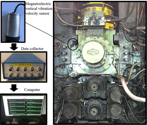
In order to obtain the vibration phenomena, the vertical vibration of the upper backup roll bearing seat of F1 stand was measured by using an electromagnetic vibration speed sensor. The parameters of the sensor are shown in Table 2.
And the parameters of the data collector are shown in Table 3. Set the sampling frequency to 1024 Hz.
The test instrument and the test site are shown in Fig. 1.
Table 1Rolling process parameters of F1 stand
Parameters | Value |
F1 speed (m/s) | 0.38 |
Rolling force (kN) | 20755 |
Bending force (kN) | 858.3 |
Table 2Parameters of the sensor
Technical specifications | Value |
Frequency response range | 1 Hz-500 Hz |
Sensitivity | 28.2 mV/(mm/s) |
Table 3Parameters of the data collector
Technical specifications | Value |
Bandwidth | 1 Hz-10 kHz |
Maximum analysis frequency | 100 kHz |
Rotation rate range | 0.01-400,00 rpm/min |
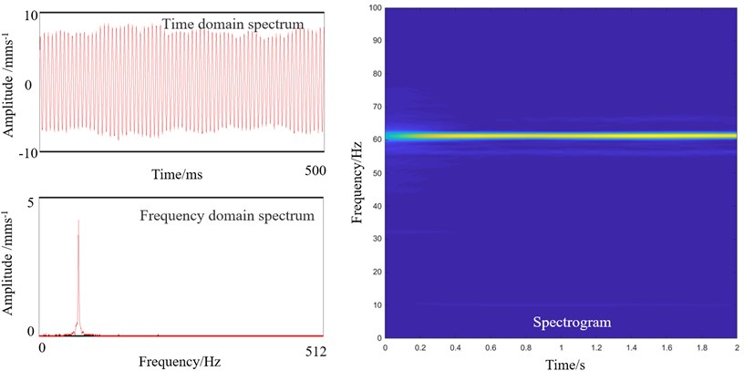
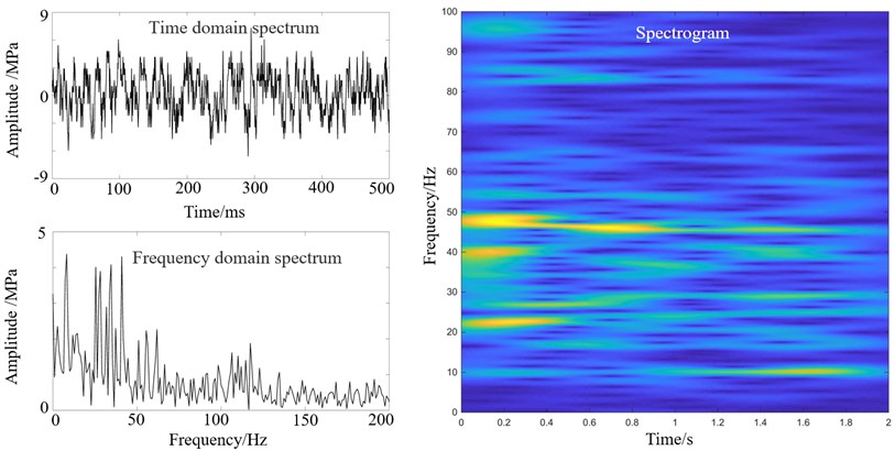
In Fig. 1, the vibration speed sensor at the bearing seat of the upper backup roll transmits the signal to the collector. The vibration signal of the bearing seat of the backup roll when rolling 2.0 mm thick strip is shown in Fig. 2.
Fig. 1Test site and test instruments
The time domain spectrum in Fig. 2 shows that the amplitude of the vibration RMS (Root Mean Square) approaches to 10 mm/s; there is a dominant frequency of 62 Hz in the frequency domain spectrum; and the spectrogram shows that the dominant frequency of 62 Hz is invariable.
After the field test, we conclude that when the 1720 hot strip mill rolls 2.0 mm thick strip, F1 stand vibrate violently with the frequency of 62 Hz, and the amplitude of the vibration RMS is large.
Fig. 2Vibration spectra of the backup roll bearing seat of F1 stand
2.2. Exploration on vibration source of hot strip mill
The strip thickness deviation and the hydraulic fluctuation of the srewdown system frequently induce rolling mill vibration, which are a significant object for scholars to study. The chatter marks on the strip result the thickness deviation with different frequencies at varied rolling speeds. Fig. 3 shows the chatter marks at the entry of F1 stand.
Fig. 3Stripes on the surface of the steel strip
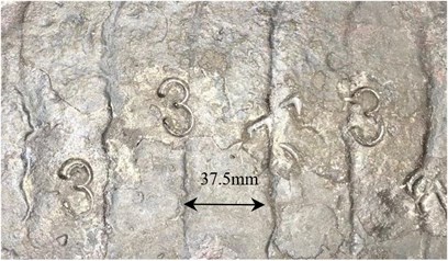
Fig. 4Spectra of strip thickness deviation and hydraulic pressure
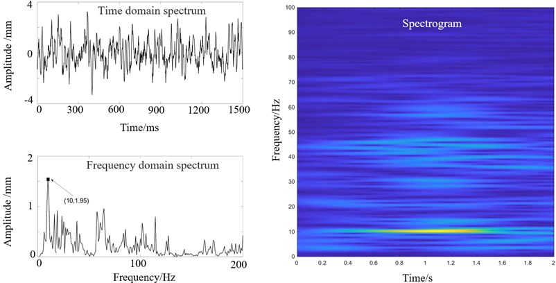
a) Spectra of the strip thickness deviation of F1 entrance
b) Spectra of the oil pressure of screw-down system of F1
In Fig. 3, we can see remarkable chatter marks on the steel strip with the width of 37.5 mm.
Fig. 4(a) shows the time-domain ,frequency-domain spectra and the spectrogram of the thickness deviation of the sample in Fig. 3 at the entrance velocity of 0.38 m/s; Fig. 4(b) shows the time domain ,frequency domain spectra and the spectrogram of the oil pressure at the outlet of the servo valve.
Fig. 4(a) indicates that the thickness deviation spectrum includes a dominant frequency of 10 Hz and other frequencies; Fig. 4(b) indicates that the oil pressure spectrum includes many frequencies in the range of 10 Hz to 50 Hz. To explore the effects of the strip and the screw-down system in vibration, following experiments are introduced.
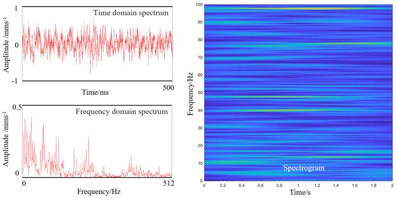
2.2.1. Stripless rolling
The experiment of stripless rolling was introduced to simulate the rolling without strip, the parameters of Table 1, except the roll gap, was applied in the experiment. The vibration spectra of the backup roll are shown in Fig. 5.
Fig. 5 shows that the frequency is dispersed with minor amplitude, and no violent vibration occurs, so we conclude that the vibration of rolling mill is related to the strip.
Fig. 5Stripless rolling vibration spectrum of the upper support roll of F1 stand
2.2.2. Turn off the AGC screw-down system
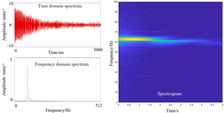
To explore the effect of the screw-down system in vibration, turning off the screw-down system was introduced. The parameters of Table 1 was applied in the experiment. Fig. 6(a) shows the vibration spectra when the screw-down system is turned off.
From Fig. 6(a), we can see that the vibration amplitude decreases rapidly in two seconds after turning off the screw-down system, and the spectrogram shows that the dominant frequency of 62 Hz remains unchanged during vibration attenuation stage. Then vibration remains weak and without dominant frequency as shown in Fig. 6(b). The results show that screw-down system has a great influence on the vibration of the rolling mill.
From the results of Fig. 5 and Fig. 6, we know that the vibration of F1 stand quickly decreases by removing the strip or turning off the screw-down system. While violent vibration occurs when two factors coexist. In conclusion, the violent vibration of the F1 stand in field test (Fig. 2) is induced by the interaction of the strip and the screw-down system.
3. The natural characteristic of the rolling mill
In order to obtain the natural characteristics of the rolling mill, the model of F1 stand of the hot strip mill is modeled and the modal is obtained by ANSYS, which are shown in Table 4.
Fig. 6Vibration spectrum of upper backup roll bearing seat of F1
a) Vibration spectra of F1 when AGC screw-down system is turned off
b) Frequency domain spectrogram of F1 after turning off the AGC screw-down system
Table 4The modal of rolling mill
Order | 1 | 2 | 3 | 4 | 5 |
Modal (Hz) | 15.455 | 22.494 | 50.428 | 61.955 | 72.031 |
Its typical fourth-order natural modal is shown in Fig. 7.
From Fig. 7 we can see that the upper half of the rack and the rolls vibrate more violently and the modal frequency is 61.955 Hz which is similar to the result of the field test in Fig. 2.
Furthermore, long-term monitoring found that the vibration frequency of rolling mill changed with the variation of the speed, and the vibration amplitude suddenly reached its maximum when the dominant frequency was 62 Hz. Therefore, combining the results of Fig. 7, we conclude that the dominant frequency of 62 Hz in field test is the natural frequency of the rolling mill.
4. Vibration characteristics of hot rolling mill excited by hydraulic pressure and strip
4.1. Mathematical model under combined excitation
In view of the weak nonlinearity of the AGC cylinder [13] of the screw-down system, the mathematical model of the rolling mill is considered as Duffing equation with a small parameter, . When an excitation includes two frequency components effects on a non-linear system, the response with more frequencies generates [14]. The response of the rolling mill with non-linear characteristics under combined excitation is introduced to interpret the reason of the resonance of in field test. The function sketch of the rolling mill is shown in Fig. 8.
Fig. 7Fourth-order natural mode of rolling mill
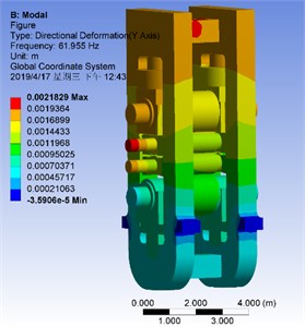
Fig. 8Drawing of rolling mill under combined excitation of hydraulic reduction and strip steel
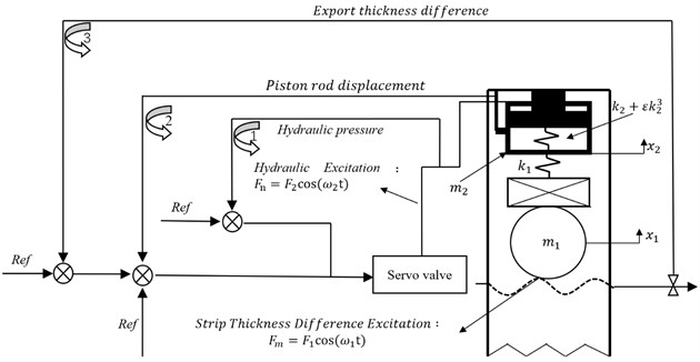
From Fig. 8 we can see that the rolls and the AGC cylinder is acted by the strip thickness difference excitation and the hydraulic excitation. Where and are the equivalent mass and the displacement of the rolls, respectively; and are the equivalent mass and the displacement of the AGC cylinder, respectively; is the contact stiffness between rolls and AGC cylinder; is the primary stiffness and is a small parameter; is the rolling force deviation induced by the hydraulic fluctuation, where is the corresponding amplitude; is the rolling force deviation induced by thickness deviation, , where is the corresponding amplitude. The dynamic equation of the mill is shown as follow:
where , (, 1, 2);; . Turns the second equation of Eq. (1) to:
and we have:
Substituted Eq. (2) and Eq. (3) (i.e. and ) to the first equation of Eq. (1), we have:
where:
The perturbation method [15] is introduced to weak nonlinear equations. Define as the periodic solution of the derived system, the solution of the original system is considered as a correction term on the derived solution. Therefore, the power series of the original system solution is obtained:
where, the subscript 1, 2. Substituting Eq. (10) to Eq. (4), and expanding the right side of Eq. (4), , into a power series of , and :
If Eq. (11) holds for any condition, the coefficients of the same power of parameter on both sides must be equal. Thus, a set of linear differential equations with approximate solutions of each order is derived. The equations of the first three orders (, and ) are shown as follow:
The derived system solution,, is obtained by solving Eq. (12), and substitute it to Eq. (13) and Eq. (14) to obtain and , then substitute them to Eq.(10) to obtain the original system solution. The solution of Eq. (12) is shown as follow:
where and are constants. Substitute Eq. (15)-(17) to Eq. (13), and combined with Eq. (9), we have:
The superscript of denotes the fourth derivative and is the coefficient of each cosine component. The solution of Eq. (18) is shown as follow:
where - is the coefficient of each cosine component. Eq. (15) and Eq. (19) are substituted to Eq. (10) to obtain :
Substitute Eq. (20) to the first equation of Eq. (1), we have:
The solution of Eq. (21) is shown as follow:
here - is the coefficient of each cosine component.
Eq. (20) and Eq. (22) show that, under the combined excitation with frequencies of , , the solution of the dynamic equations contain eight frequencies (i.e.). Thus, even if the system is only affected by two excitation frequencies, the response frequencies are very rich. Some response frequencies approach to the natural frequency of the mill can induce resonance. From Fig. 4 and Fig. 5, we can see that the screw-down-strip combination excitation frequencies are more than two, thus the response frequencies are more than that with two excitation frequencies, and it is more possible to induce vibration.
4.2. Frequency domain simulation of vertical system of rolling mill under combined excitation
The above theoretical analysis shows that the rolling mill generates multiple response frequencies under combined excitation of two frequencies. Simulink is introduced to obtain the response frequencies with three and four excitation frequencies. The responses and in Eqs. (12) and (13) are obtained with the state space module. Then substitute them to Eq. (20) to obtain (the displacement of the AGC cylinder). Eq. (12) is transformed into a state equation, and the state variables are shown as follow:
The matrix and vector are denoted with bold front. The derivative of Eq. (23) is shown as follow:
The output equation, , is defined as:
And the excitation, , is expressed as:
The matrix form of the state equation is denoted as:
where:
Eq. (13) is also converted to state equation with the same method. The simulation parameters are shown in Table 5.
Table 5Value of simulation parameters
Name | Code | Value | Unit | Note |
Equivalent mass of upper rolls | 0.93×10⁵ | kg | ||
Equivalent mass of AGC cylinder | 0.12×10⁵ | kg | ||
Contact stiffness between roll system and AGC cylinder | 1.12× 10⁸ | N/m | ||
The primary term of the nonlinear stiffness | 8.66×10⁶ | N/m | ||
Amplitude of exciting force of strip | 0.62×10⁶ | N | ||
Amplitude of exciting force under hydraulic pressure | 0.78×10⁶ | N | ||
Parameter 1 | 12.91×10⁵ | N(mkg)-1 | Defined in Eq. (5) | |
Parameter 2 | 24.44×10¹⁰ | N2(mkg)-2 | Defined in Eq. (6) | |
Parameter 3 | 6.97×10⁶ | N3m-2kg-3 | Defined in Eq. (7) | |
Parameter 4 | 4.59×10⁵ | N3m-2kg-3 | Defined in Eq. (8) | |
Nonlinear parameters | 0.02 |
The parameters selected in the state-space module in Simulink are A, B, C and D in Eq. (27), respectively. After substituting the parameters in Table 2. the simulation model of the rolling mill under combined excitation based on the perturbation method can be obtained, as shown in Fig. 9.
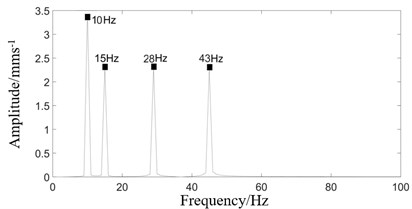
Fig. 9 shows the simulation model with three sinusoidal combined excitations. The vibration response of the model is shown in Fig. 10.
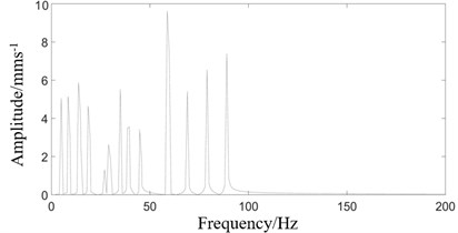
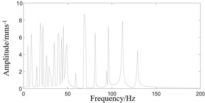
Fig. 10 shows that when the number of combined excitations is three, the number of frequencies in the response spectrum is more than that under two excitations. Similarly, when the number of combined excitations is four, the response spectrum is shown in Fig. 11.
Fig. 11 shows that when the number of combined excitations is four, the number of frequencies in the response spectrum is more than that under two and three excitations.
Combining the results in Fig. 10 and Fig. 11, we know that with the increase of the combined excitation frequencies, the response frequencies of the rolling mill also increase, which makes it more possible to generate the response frequencies approach to the natural frequency and induce the resonance.
Fig. 9Simulation model of vibration characteristics of vertical system of rolling mill under combined excitation
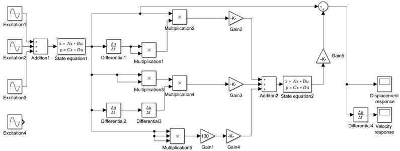
Fig. 10Frequency spectrum of rolling mill vibration response under three excitation combinations
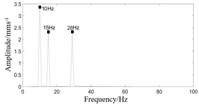
a) Three excitations spectrum
b) Response spectrum under three excitations
Fig. 11Frequency spectrum of rolling mill vibration response under four excitation combinations
a) Four excitations spectrogram
b) Response spectrum under Four excitations
5. Vibration suppression of rolling mill
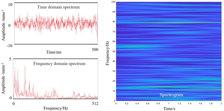
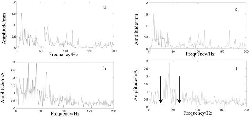
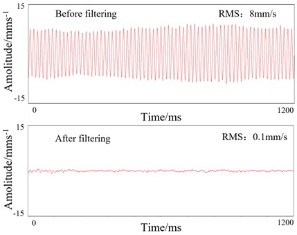
According to the conclusion of the previous chapters, the idea of vibration suppression is introduced by reducing the number of output frequencies of the system. There are far more than two excitation frequencies in the rolling mill under actual working conditions. Generally, the roll gap position regulator receives multiple reference signals and feedback signals. Therefore, a filter is added to the AGC system control loop to filter the input current signal of the servo valve to reduce the frequencies of the oil pressure at the outlet of the servo valve, and a monitoring system is installed at the bearing seat of the upper backup roll. By gradually adjusting the filtering range and observing the vibration signal in the monitoring system until the vibration signal of the upper roll system is not approach to the natural frequency (62 Hz) of the mill, the optimum filtering range is obtained. The effects before and after filtering are shown in Fig. 12, where a)-d) are the spectra without filtering, followed by the thickness deviation on strip surface, the input current of servo valve, the oil pressure of servo valve outlet and vibration of bearing seat of backup roll on F1; while e)-h) is the corresponding spectra after filtering. The arrow in the spectrum f is the filtering frequency range, which is 20 Hz-30 Hz and 57 Hz-67 Hz, respectively. We can see that the number of frequencies of oil pressure at the outlet of servo valve decreases after filtering. When the combined frequencies of the screw down system and the strip steel acts on the system, no response frequency approach to the natural frequency of the rolling mill (62 Hz), so the mill does not vibrate violently. Fig. 13 shows the time dominant spectrum of d and h in Fig. 12.
Fig. 12Vibration comparison of rolling mill before and after filtering
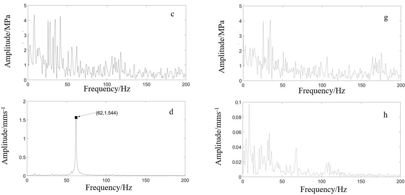
From Fig. 13 we can see that due to the absence of the dominant frequency of 62 Hz after filtering, the vibration RMS (Root Mean Square) decreased by 98.7 %, which indicated the proposed method achieves effective vibration suppression effect.
Fig. 13Vibration RMS of rolling mill before and after filtering
6. Conclusions
1) Field test shows that F1 stand of 1720 hot strip mill vibrates violently when rolling 2.0 mm thick strip. Two experiments, stripless rolling and turning off AGC cylinder, are introduced to obtain the relation among strip, screw-down system and the vibration. The result of stripless rolling shows that the vibration amplitude is weak, therefore we conclude that the vibration of rolling mill is related to the strip. And the result of turning off AGC cylinder shows that the screw-down system has a great influence on the vibration of the rolling mill. The results of the experiments indicate that the vibration of F1 stand can quickly decreases by removing the strip or turning off the screw-down system. In conclusion, the violent vibration in field test (Fig. 2) is induced by the interaction of the strip and the screw-down system.
2) Considering the non-linear of AGC cylinder of rolling mill, the dynamic model of the upper rolls and the AGC cylinder under the combined excitation of screw-down system and strip is established. The dynamic model is solved by perturbation method, and the solution shows that under the combined excitation with frequencies of and , the solution of the dynamic equations contain eight frequencies (i.e. ). Simulink is introduced to obtain the response frequencies when the number of the excitation frequencies is three and four, and the result shows that more combined excitation frequencies will generate more response frequencies, and it is more possible to have the frequency approach to the natural frequency of the rolling mill and induce the resonance.
3) A filter is introduced in the AGC control loop to filter the input current signal of the servo valve to reduce the frequencies of the oil pressure at the outlet of the servo valve, and a monitoring system is installed at the bearing seat of the upper backup roll to verify the effect of filtering, and we find that when the filtering frequency ranges are set to 20 Hz-30 Hz and 57 Hz-67 Hz, the vibration of F1 stand is weak with no dominant frequency. Due to the absence of the dominant frequency of 62 Hz after filtering, the vibration RMS (Root Mean Square) decreased by 98.7 %.
References
-
Gao Z., Zang Y., Zeng L. Review of modelling and theoretical studies on chatter in the rolling mills. Journal of Mechanical Engineering, Vol. 51, Issue 16, 2015, p. 87-105.
-
Zhang Yifang, Yan Xiaoqiang, Lin Qihui Research on torsional vibration of main drive system under multi-source excitation in CSP rolling mill. Journal of Mechanical Engineering, Vol. 53, Issue 10, 2017, p. 34-42.
-
Shi Peiming, Xia Kewei, et al. Non-main resonance characteristics of nonlinear torsonal vibration of rolling mill’s multi-degree-of-freedom main drive system. Journal of Vibration and Shock, Vol. 34, Issue 12, 2015, p. 35-41.
-
Lin Qihui, Yan Xiaoqiang, Zhang Qingdong, et al. Research on vibration characteristics of the hot rolling mill by dual power source driven. Vibration test and diagnosis, Vol. 34, Issue 3, 2014, p. 534-538+594.
-
Yan Xiaoqiang, Wu Xianfeng, Yang Xien, et al. Coupling research on torsional vibration and axial vibration of hot strip rolling mill. Engineering Mechanics, Vol. 31, Issue 2, 2014, p. 214-218.
-
Shi Peiming, Xia Kewei, Liu Bin, et al. Dynamics behaviors of rolling mill’s nonlinear torsional vibration of multi-degree-of-freedom main drive system with clearance. Journal of Mechanical Engineering, Vol. 48, Issue 17, 2012, p. 57-64.
-
Liu Fei, Liu Bin, Hou Dongxiao Vibration behavior of roll system under nonlinear constraints of the hydraulic cylinder. Journal of Mechanical Engineering, Vol. 50, Issue 24, 2014, p. 59-65.
-
Wang Zhe, Wang Jing, Zhang Yongjun, et al. Active disturbance rejection synchronous control for both sides of hydraulic servo position system of rolling mill. Control Theory and Application, Vol. 30, Issue 12, 2013, p. 1602-1608.
-
Jin Baoquan, Xiong Shibo, Liang Yiwei, et al. Modeling and simulation for rolling mill servo screw-down system involving dynamic stiffness of displacement feedback apparatus. China Mechanical Engineering, Vol. 11, 2008, p. 1330-1335.
-
Gao Zhiying, Bai Lulu, Li Qiang, et al. Research on critical rolling speed of self-excited vibration in the tandem rolling process of thin strip. Journal of Mechanical Engineering, Vol. 53, Issue 12, 2017, p. 118-132.
-
Liu Haoran, Zhang Ying, Shi Peiming, et al. Vibration characteristics of a cold rolling MLL with a model of seven degrees of freedom and their influence on dynamic rolling force. Journal of Vibration and Shock, Vol. 34, Issue 22, 2015, p. 98-102+120.
-
Sun Yunyun, Xiao Huifang, Xu Jinwu Nonlinear vibration characteristics of a rolling mill system considering the roughness of rolling interface. Journal of Vibration and Shock, Vol. 36, Issue 8, 2017, p. 113-120.
-
Wang Linhong, Wu Bo, Du Runsheng, et al. Nonlinear dynamic characteristics of hydraulic cylinder motion. Journal of Mechanical Engineering, Vol. 12, 2007, p. 12-19.
-
Liu Yanzhu, Chen Liqun Onlinear Vibration. Higher Education Press, Beijing, 2001.
-
Hou Dongxiao, Chen Hao, Liu Bin, et al. Analysis on parametrically excited nonlinear vertical vibration of roller system in rolling mills. Journal of Vibration and Shock, Vol. 28, Issue 11, 2009, p. 1-5.
-
Ou Jinping Structural Vibration Control-Active, Semi-Active and Intelligent Control. Science Press, Beijing, 2003.
About this article

