Abstract
In order to carry out a more in-depth study on the vibration characteristics of the marine power-spilt gear system, a nonlinear dynamic model of a certain type of marine gearbox was established, taking into account factors such as dynamic backlash and time-varying mesh stiffness. The numerical simulation method was used to calculate the variation of the system vibration response with input speed, the torsional stiffness of the linkage shaft and the stiffness of the output shaft under different backlach. The results show that the system will occur resonance as the input speed increases; the torsional stiffness of the linkage axis has an optimal value, so that the vibration response amplitude of the system is the smallest; as the support stiffness of the output shaft increases, the vibration acceleration of the output shaft does not change much, while the vibration displacement is significantly reduced.
1. Introduction
The backlash is one of the main factors causing the vibration of the gear system. Therefore, many literatures have studied the influence of the backlash on the dynamic characteristics. Kahraman [1] and Jeffrey L. Stein [2] studied the effects of the nonlinearity of the system with the amplitude of the backlash on the gear speed fluctuation. Fuhao Liu [3] established a vibration-shock model of gear system considering tooth surface lubrication and backlash. The power-spilt gear system was first applied in helicopters and has been studied in a large number of documents. Rsshidi [4] and Krantz [5] studied the dynamics and load sharing characteristics of the helicopter power-spilt drive system. Bechhoefer [6] studied the performance state quantification method of the power-spilt gearbox by using various gear analysis algorithms. The development of modern ship technology promotes the research and development of the marine power-spilt gear system. Zhang Ting [7] and Li Nan [8] solved the dynamic load coefficients of the power-spilt system. Chang Lehao [9] and Wang Feng [10] established a system model considering the factors of bearing stiffness, time-varying meshing stiffness and transmission error.
In this paper, a kind of marine dual-input power double-branch gear transmission system is taken as the research object, and a dynamic model considering nonlinear factors such as time-varying meshing stiffness and time-varying backalsh is established. The study of the influence of input speed, torsional stiffness of the linkage shaft and support stiffness on the vibration characteristics of the system provides a theoretical basis for the analysis and design of the marine power-splot train.
2. Dynamic model of system
The three-dimensional model structure of a power-split gear system is shown in Fig. 1. The input end is connected to the high-pressure output end and the low-pressure output end of the steam turbine respectively. The power transmission route of the system is naturally divided into a high-pressure set and a low-pressure set. In order to improve the transmission efficiency and increase the transmission power, the high and low pressure sides respectively adopt the form of power double branch, and the power from the main engine is finally transmitted to the output shaft through the meshing. In Fig. 1, donates gears, is used to indicate a I-stage pinion of high-pressure side; , indicate I-stage large gears of high-pressure side respectively; , donate II-stage small gears; is I-stage output large gear; , , , and are gears of low-pressure side correspond to the high-pressure side. The gear pairs of each stage are driven by herringbone gears. The I-stage large gears are connected to the II-stage small gears through the linkage shaft.
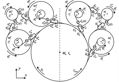
The dynamics model of a marine power-spilt gear system is shown in Fig. 2. It is assumed in the modeling that the hub is a rigid body and the gear teeth are elastic; the bearings at both ends of the gear shaft have the same parameters and dynamic characteristics; the two helical gears that make up the herringbone gear have the same meshing stiffness, meshing damping and static transmission error; considering the torsional deformation of the drive shaft.
In this model, the influence of tooth surface friction and eccentricity are not considered. It is considered that the bearing support stiffness and damping are constant, while ignoring the axial vibration of the herringbone gear. In Fig. 2, indicates the input torque ( for the high-pressure end, for the low-pressure end, the same below), the load torque is ; and are torsion angles of each gear, (1, 2,..., 5, the same below) is the inertia moment of each gear assembly; and are the concentrated mass of each gear assembly; (1, 4, 5; 2, 3, 6) indicates the dynamic meshing stiffness; is the meshing damping; donates backlash; indicates static transmission error. Based on the above analysis, the generalized displacement vector of the system can be expressed as:
Fig. 1Model structure of the marine power-spilt gear system
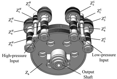
Fig. 2Dynamic model of power-spilt gear system
3. System dynamic differential equation
As the gear rotates and the bearing clearance changes, the center coordinate of the gear changes with time, which causes the meshing center distance and the meshing angle to change, so that the backlash is also in dynamic change. The dynamic backlash can be expressed as:
where donates initial backlash, ,, , are initial installation center distance and pressure angle, , are dynamic center distance and pressure angle respectively, where dynamic center distance can be expressed as:
According to the segmentation characteristics of the backlash, the nonlinear function of the dynamic backlash can be expressed by the following formula:
where is gear meshing dynamic transfer error function.
Considering the linear displacement of the gear torsion direction to the meshing line and the static transmission error , the dynamic gear transmission error can be expressed as:
The dynamic meshing force between the gears can be expressed as:
Considering that the high-pressure set and the low-pressure set structure in the transmission system are symmetrical, the differential equation is the same. This paper only deduces the differential equation of the high-pressure set transmission system. The force state of each gear is analyzed, and the Lagrange equation is used to obtain the differential equations of motion of each gear pair, the equation of system can be expressed as:
where , , , indicate bearing stiffness and damping in the and directions of the gear respectively; , , , donate meshing force. , , , are the angle between the end-direction meshing line and the x positive direction; indicates gear index circle radius; , are torque moments transmitted by the linkage shaft.
4. Analysis of vibration characteristics of system
This paper is numerically simulated on the basis of the mathematical model of the concentrated mass to study the effect of backlash, the input speed, the linkage shaft stiffness and the bearing support stiffness on the vibration characteristics of the system. The fourth-order fixed-step Runge-Kutta algorithm is used to solve the system differential equations. System parameters are shown in Table 1.
The initial backlash is taken as 0.3 mm, 0.8 mm and 1.3 mm respectively. The calculated output vibration acceleration and vibration displacement are found to be the root mean square value (RMS), which is used to indicate the vibration response of the system under given parameters.
Table 1Parameters of gears
Dimension parameters | I-stage pinion of high/low pressure set | I-stage large gear of high/low pressure set | II-stage pinion | II-stage large gear | |
Number of teeth | 32/40 | 138/130 | 30 | 278 | |
Normal modulus/mm | 5 | 8 | |||
Pressure angle/° | 20 | ||||
Helix angle/° | 25 | 20 | |||
4.1. Influence of input speed on system vibration characteristics
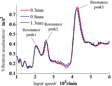
The input speed is increased from 1000 r/min to 6000 r/min. The response characteristics of the power-split system with input speed are studied under different backlash. The calculation results are shown in Fig. 3.
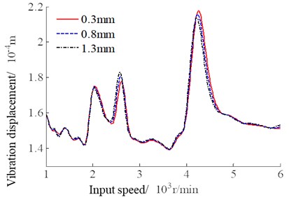
It can be seen from the curves in Fig. 3 that there is no significant difference in the vibration response of the system under different backlash, indicating that the backlash between the two gear pairs of the power-split train has little effect on the output vibration characteristics of the system. With the increase of the input speed, the vibration acceleration and vibration displacement curves of the output end show the same change trend, and the resonance peaks appear. As shown in Fig. 3, the main three resonance peaks are 2100 r/min, 2600 r/min and respectively 4300 r/min, and the amplitude of the resonance peak increases with the increase of the input speed, in which the vibration at the third resonance peak is the largest. Therefore, in order to ensure the safety and stability of the system work, the above input speed should be avoided during operation.
Fig. 3System vibration response with the changes of input speed
4.2. Influence of torsional stiffness of linkage shaft on vibration characteristics of system
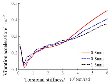
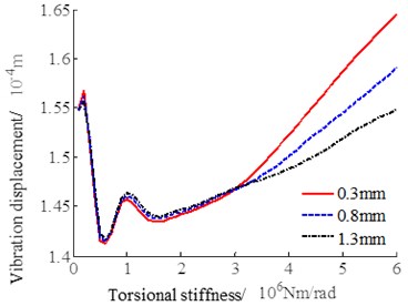
The torsional stiffness of the linkage shaft is increased from 105 Nm/rad to 107 Nm/rad, and the vibration response of the output shaft is numerically simulated. The calculation results are shown in Fig. 4.
It can be seen from the curves in Fig. 4 that within the range of torsional stiffness, the output vibration response decreases first and then increases with the increase of torsional stiffness. When the torsional stiffness is 5×10⁵ Nm/rad, the system vibration response amplitude is minimum. When the torsional stiffness is less than 3.1×10⁶ Nm/rad, the influence of the backlash on the vibration response is not significant. When the torsional stiffness is greater than the above value, the influence of the backlash increases, and the smaller the backlash, the greater the system vibration response. From the above analysis, it suggests that the torsional stiffness of the linkage shaft is best when 5×10⁵ Nm/rad is taken, and if the actual torsional stiffness is greater than 3.1×10⁶ Nm/rad, the backlash should not be too small.
Fig. 4System vibration response with the change of torsional stiffness of the linkage shaft
4.3. Influence of output shaft support stiffness on system vibration characteristics
The support stiffness of output shaft increases from 108 N/m to 109 N/m, and numerical simulation is performed. The calculation results are shown in Fig. 5.
Fig. 5System vibration response with the changes of support stiffness of the output shaft
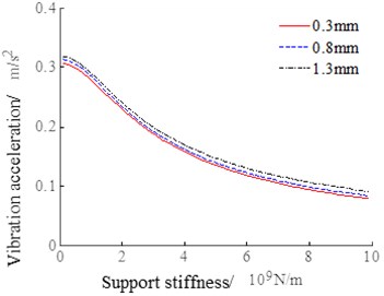
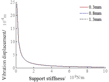
It can be seen from the curves in Fig. 5 that the backlash has little effect on the system vibration response. As the output shaft support stiffness increases, the vibration acceleration RMS value changes less, decreasing from 0.3 m/s2 to 0.1 m/s2. The output shaft support stiffness has a significant influence on the vibration displacement, ss which increases, the vibration displacement decreases from 24 mm to 0.03 mm, and the support stiffness has a significant change in the RMS value of the vibration displacement in the 108 N/m~2×108 N/m interval. When the support stiffness is greater than 2×10⁸ N/m, the vibration displacement RMS does not change significantly with the support stiffness.
5. Conclusions
In this paper, a marine gear system is established, the dynamic backlash and time-varying meshing stiffness are considered. Taking the vibration characteristics of the system output as the research target, the vibration responses of the system with the input speed, the torsional stiffness of the linkage shaft and the support stiffness of the output shaft under different backlash are calculated. The following conclusions can be drawn by analyzing the results:
1) As the input speed increases, the system will have a resonance phenomenon. The input speeds at resonance peaks occurs are 2100 r/min, 2600 r/min and 4300 r/min respectively. In practice, the system should avoid the above input speed.
2) The optimal value 5×10⁵ Nm/rad of the torsional stiffness of the linkage axis makes the vibration response minimum, and it increases with the increase of the torsional stiffness. The smaller the backlash is, the larger the vibration amplitude is.
3) As the support stiffness increases, the vibration acceleration of the output shaft does not change much, while the vibration displacement decreases.
References
-
Kahraman A., Singh R. Non-linear dynamics of a spur gear pair. Journal of Sound and Vibration, Vol. 142, Issue 1, 1990, p. 49-75.
-
Jeffrey L. S. Estimation of gear backlash: theory and simulation. Transactions of the ASME, Vol. 120, 1998, p. 74-82.
-
Liu F., Zhang L., Jiang H., et al. Simulation of vibro-impact gear model considering the lubricant influence with a new computational algorithm. Journal of the Brazilian Society of Mechanical Sciences and Engineering, Vol. 40, 2018, p. 147.
-
Rashidi M. Dynamics of a split torque helicopter transmission. Proceedings of the International Power Transmission and Gearing Conference, Scottsdale, 1992, p. 347-358.
-
Krantz T. L., Rashidi M., Kish J. G. Split torque transmission load sharing. Proceedings of the Institution of Mechanical Engineers Part G Journal of Aerospace Engineering, Vol. 208, 1992, p. 137-148.
-
Bechhoefer E., Li R., He D. Quantification of condition indicator performance on a split torque gearbox. Journal of Intelligent Manufacturing, Vol. 23, Issue 2, 2012, p. 213-220.
-
Zhang T., Li Y., Wang S. Research on static load sharing of the dual path gear transmission. Journal of Mechanical Transmission, Vol. 36, Issue 3, 2012, p. 14-17.
-
Li N., Wang S., Du J. Natural characteristics and dynamic load coefficient of power four embranchments gear transmission. Journal of Aerospace Power, Vol. 28, Issue 2, 2013, p. 445-451.
-
Chang L., Liu G., Zhou J. Research on dynamic characteristics of dual-branching gear system. Journal of Ship Mechanics, Vol. 17, Issue 10, 2013, p. 1176-1184.
-
Wang F., Fang Z., Li S. Treatment and contrast verification of meshing stiffness in dynamic model of helical gear. Journal of Vibration and Shock, Vol. 33, Issue 6, 2014, p. 13-17.
About this article

