Abstract
The paper analyzes the possible motion modes of an unbalanced rotor with an auto-balancing device. It is shown that for given parameters of the system, there are several qualitatively different stable motion modes. Previously unknown types of motion modes are detected. It is found that for a given supercritical working rotor speed, the system can have at least three possible stable motion modes depending on the initial conditions of its motion. A qualitative analysis of the stability ranges of all possible motion modes of the system was performed.
1. Introduction
The use of auto-balancing devices allows reducing vibration and improving the reliability of rotary machines. In the works on the autobalancer study (see [1-7] and others), only two possible modes of its motion are considered - the mode of auto-balancing and the mode of rotation of compensating bodies in the autobalancer cavity. The rotor auto-balancing mode is the main useful motion mode of the mechanical system, since in this case, the autobalancer compensating bodies automatically eliminate the existing rotor imbalance and reduce its vibration. The boundaries of stability of this motion mode have been studied in a series of papers, for example, [1, 3, 4, 8] and others.
It should be noted that the mechanical system “rotor-autobalancer” is a nonlinear system. Therefore, it has non-trivial dynamic properties. Such systems can have not one but several stable motion modes at the same time. It depends on the initial conditions. One of the additional motion modes of this system is the mode in which the compensating bodies permanently rotate in the autobalancer cavity at approximately constant speed, lagging behind the rotor rotation. This additional mode of motion was noted and studied in [2, 4, 9].
However, it can be supposed that in such system, there may be other additional modes of steady motion. It is obvious that the incomplete knowledge about the dynamic behavior of the autobalancer, together with other factors, makes the practical application of these devices difficult. In addition, the study of all possible stable system movements is necessary to create a complete bifurcation theory of autobalanced rotors.
The aim of this work is to identify and analyze additional motion modes of compensating bodies of the rotor autobalancer.
2. Mechanical system model
Caption Fig. 1 shows a scheme of a ball auto-balancing device mounted on a rotating rotor. The single-disk isotropic unbalanced Jeffcott rotor is mounted on two elastic supports with viscous damping and rotates at a constant angular speed . The disk of mass is installed in the middle of the shaft and makes a plane motion. Its center of mass is spaced from the point A attaching the disc to the shaft at a distance (eccentricity).
Fig. 1Mechanical system “rotor – autobalancer”
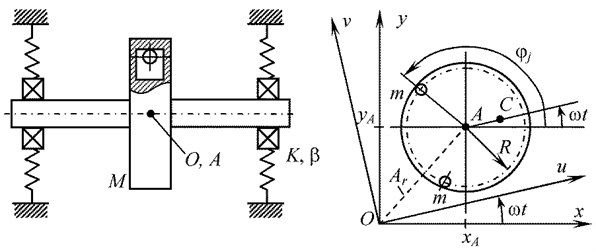
Autobalancer is located in the disk plane. It is designed as a circular cavity with compensating bodies in the form of balls or rollers (also it is possible to use a pendulum compensating bodies). The axis of the circular cavity of the autobalancer passes through the point , in which it is attached to the rotor. The number of compensating bodies is arbitrary, but not less than two, ≥ 2. Bodies are able to move freely around a circle of radius . The model assumes that motion of one compensating body does not prevent the motion of other bodies.
The motion of the mechanical system is described both in the fixed coordinate system and in the rotating coordinate system (see Fig. 1).
The current position of the disk is characterized by the coordinates , of point , and the angular position of the th body – by the angle measured from the fixed axis x.
Physical parameters of the mechanical system: – angular speed of rotor rotation, rad/s; , – mass of the disk, kg, and rotor eccentricity, m; – stiffness of the shaft and its supports, corresponding to the center of the disk, N/m; – coefficient of external viscous damping of the rotor, s-1; – critical rotation speed of the rotor, rad/s; , – current coordinates of the disk geometric center, m; , – mass of one compensating body (kg) and their quantity; R - radius of the circle of bodies movement in the autobalancer, m; – coefficient of internal viscous resistance to the movement of the compensating body in the autobalancer, s-1; – current angular coordinate of the th body relative to the axis in the fixed coordinate system, rad; – current angular coordinate of the th body relative to the axis u in the rotating coordinate system, rad; – constant angular positions of the bodies relative to the disk in the auto-balancing mode, rad.
The generalized coordinates of the mechanical system under consideration are as follows: , , , 1, 2, …, or , , , 1, 2, …, .
The equations of motion of the system are known (see [3, 4] and others). The system of equations of motion can be represented in the following dimensionless form:
where the dimensionless parameters of the mechanical system:
; – dimensionless time.
Here the dot above the symbol means the operation of differentiation by dimensionless time .
3. Motion modes of the mechanical system “rotor - autobalancer”
The analysis of the motion modes of the mechanical system was carried out by numerical calculations of differential equations (1) for a rotor with a two-mass auto-balancing device at a working rotation speed . The calculations were performed for the following values of dimensionless parameters 2; 0.007; 76.23; 0.1; 0.001; 3. With this data, the autobalancer capacity is equal to 1.082, and the auto-balancing positions of bodies are ±157.5 degrees. Calculations of the transition process from the initial system state to steady-state motion were performed by the Runge-Kutta method using the Mathcad program. Differences in calculations are only in the values of the initial parameters of the system state. All the graphs below correspond to steady-state modes of motion after the end of transients. A total of 2000 rotor revolutions were calculated. Note that one rotor revolution corresponds to a dimensionless time 2.094.
The computational analysis revealed that the rotor with the autobalancer has several motion modes that are qualitatively different from each other. To identify the stability ranges of various motion modes, calculations were also performed at different rotor speeds . Descriptions of these motion modes are given below.
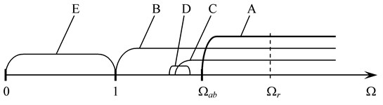
A. Auto-balancing motion of the system. This mode is the main beneficial motion of the system, since it provides reduced vibration to the unbalanced rotor. Theoretically, this mode can exist at supercritical rotor speed, i.e. at > 1. However, the real lower stability boundary of auto-balancing exceeds the critical rotor speed 1. Therefore, the auto-balancing motion mode is stable under the condition > > 1. To calculate the value of the stability boundary , it is possible to use the results of research papers [4, 10, 8]. Fig. 2 shows a visual scheme of the stability range of the rotor auto-balancing according to the parameter .
Fig. 2Ranges of motion modes of the non-linear system “rotor - autobalancer”: A – auto-balancing system motion (main mode), B – mode of rotation of bodies in the autobalancer, C – mode of double oscillations of bodies in the autobalancer, D – mode of half-rotation of bodies in the autobalancer, E – unbalanced movement of the system
In the auto-balancing mode, compensating bodies rotate with the disk and at the same time make small oscillations relative to the angular positions , at which the total imbalance of the rotor and the bodies is zero. Fig. 3 presents a scheme and graphs illustrating the auto-balancing mode. Graphs are obtained by numerical calculation of the system (1) with the above mentioned system parameters. In this case, the initial state of the system is given by the following values: 0, 180±5 degrees, 0. In the initial state, the compensating bodies rotate in the autobalancer cavity at the same speed as the rotor.
Fig. 3-5 show graphs of the dependencies:
• Transversal displacement of the rotor on the dimensionless time ;
• Relative angular positions of compensating bodies in the autobalancer;
• Phase portraits of the relative movement of bodies.
Fig. 3The graphs illustrating the auto-balancing motion of the system
B. The mode of rotation of bodies in the autobalancer. This mode is implemented if the initial speed of autobalancer bodies is substantially less than the rotor speed, for example, 1, i.e., bodies could not accelerate to the rotor speed. As can be seen from the graphs in Fig. 4, in this mode, the transverse vibration of the rotor is significantly larger than in mode A. The bodies rotate in the autobalancer cavity at approximately constant speed, lagging behind the rotor speed (see graph in Fig. 4). Therefore, the values of the bodies’ angular positions relative to the rotor increase indefinitely. The phase portrait of the bodies’ movement is not closed, which indicates a non-periodic mode of their movement relative to the rotor. The mode of bodies’ rotation is stable in the whole superresonance region of the rotor speed ( > 1). This motion mode was studied, for example, in [2, 4, 9, 11].
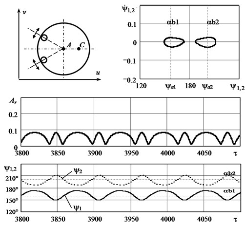
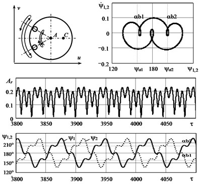
C. The mode of double oscillations of bodies in the autobalancer. A careful study of the influence of the initial conditions has shown that another dynamically stable motion mode can exist in this mechanical system, which is fundamentally different from the previous modes. In this mode, each autobalancer body alternately oscillates relative to one auto-balancing position , then relative to the other, and so on. In general, it appears that the bodies oscillate relative to two positions at once (see. scheme of Fig. 5). Given this nature of motion, this mode can be called the mode of “double oscillations” of bodies. The existence of this motion mode was first discovered in [9].
Fig. 5 shows the dynamic characteristics of the mode of double oscillations. The graphs are calculated at the initial relative speed of bodies –0.1. In the initial system state, the autobalancer bodies almost (but not quite) accelerated to the rotor speed. As can be seen from the graphs, in this motion mode, the rotor vibration is greater than the vibration during auto-balancing (mode A). The phase portraits of the first and second bodies coincide, but they move in antiphase. The average position of the compensating bodies is close to 180 degrees. The graphs in Fig. 5 correspond to the periodic motion of bodies. However, numerous calculations under various initial conditions have shown that the quasi-periodic motion is most often realized, in which the phase portraits are “blurred”.
From the point of view of the rotor machine vibroactivity, the mode of double oscillations holds an intermediate position between the auto-balancing mode (A) and the mode of rotation of bodies (B). In general, this mode can be considered favorable for the machine durability.
It can also be noted that mode C exists, but not with all possible values of system parameters. Apparently, this mode is most probable when the autobalancer capacity is slightly larger than one and the parameter is small. The mode of double oscillations of bodies is stable in a wide range of rotor speed , which is shown schematically in Fig. 2.
D. The analysis showed that there may be one more motion mode of the system in case the autobalancer bodies did not accelerate to the rotor speed. In this mode, one of the bodies rotates with the rotor and performs small periodic oscillations relative to the disk lightweight part 180 degrees. At the same time, the second body permanently rotates in the autobalancer cavity at approximately constant speed, lagging behind the rotor rotation. Given this nature of motion, this mode can be called the mode of “half-rotation of bodies” in the autobalancer.
The mode of half-rotation of bodies is stable in a relatively narrow range of rotor speed (see Fig. 2), for example, with initial parameters 2, –0.1. In general, this mode precedes the stability region of modes C and A. The vibration amplitude of the rotor in mode D exceeds the amplitude of vibration in mode C, but less than the vibration in mode B. As far as the authors know, the existence of the mode of half-rotation of bodies in the autobalancer is found for the first time.
E. Unbalanced movement of the system. This is a known motion mode, when the autobalancer bodies are stably located in the “heavy” part of the rotor disk, rotate with it, and oscillate relative to the angular position 0 deg. In this case, there is increased rotor vibration. This motion mode is the only stable mode at the sub-resonance rotor speed, when < 1 (see Fig. 2).
It should be noted that there are other additional motion modes of steady system (besides those described above), if the system model takes into account the possibility of shock of autobalancer bodies against each other [4].
Fig. 4The graphs illustrating the mode of rotation of bodies in the autobalancer
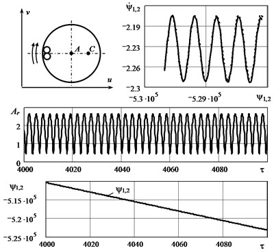
Fig. 5The graphs illustrating the mode of double oscillations of bodies in the autobalancer
4. Conclusions
The analysis showed that the nonlinear mechanical system “rotor - autobalancer” has at least five modes of steady motion depending on the rotor speed and the initial conditions. Two additional stable motion modes, besides the previously known modes, were found. These additional modes are the mode of double oscillations of bodies in the autobalancer and the mode of half-rotation of bodies.
It is established that at a given supercritical working rotor speed, the system can have at least three possible stable motion modes at the same time. Motion modes are implemented depending on the system parameters and the initial conditions of its motion. In this paper, a qualitative analysis of the stability ranges of all possible system motion modes was performed according to the rotor speed parameter.
The obtained results expand the knowledge about the features of the dynamic behavior of this mechanical system and will be useful for the practical design and operation of rotary machines with the auto-balancing device.
References
-
Nesterenko V. P. Automatic Balancing of Rotor of Devices and Machines with Many Degrees of Freedom. Tomsk University Publishing, Tomsk, 1985, p. 84, (in Russian).
-
Artunin A. I. The study of the motion of the rotor with auto-balancing device. Proceedings of Higher Educational Institutions. Machine Building, Vol. 1, 1993, p. 15-19, (in Russian).
-
Gorbenko A. N. On the stability of self-balancing of a rotor with the help of balls. Strength of Materials, Vol. 35, Issue 3, 2003, p. 305-312, https://doi.org/10.1023/A:1024621023821.
-
Fіlіmonіhіn G. B. Balancing and Vibration Protection of Rotors by Autobalancers with Solid Corrective Weights. Kirovograd, KNTU, 2004, p. 352, (in Ukrainian).
-
Green K., Champneys A. R., Friswell M. I., Munoz A. M. Investigation of a multi-ball, automatic dynamic balancing mechanisms for eccentric rotors. Philosophical Transactions of the Royal Society A, Vol. 366, 2008, p. 705-728, https://doi.org/10.1098/rsta.2007.2123.
-
Bykov V. G. Auto-balancing of a rotor with an orthotropic elastic shaft. Journal of Applied Mathematics and Mechanics (Prikladnaya Matematika i Mekhanika), Vol. 77, Issue 4, 2013, p. 369-379, https://doi.org/10.1016/j.jappmathmech.2013.11.005.
-
Strautmanis G., Grinevich I., Strautmane V. The influence of automatic equalizer and rotor parameters on the ball’s motion mode. Mechatronic Systems and Materials, 2014, p. 135-141.
-
Gorbenko A. Analytical determination of the stability movement boundaries of the Jeffcott rotor with multi-bodies autobalancer. Vibroengineering Procedia, Vol. 8, 2016, p. 152-157.
-
Gorbenko A. N. About the motion modes of the ball autobalancer mounted on a rotating rotor. Mechanization of production processes in fisheries, industrial and agricultural enterprises. Collection of scientific works of the Kerch Maritime Technological Institute, Vol. 7, 2006, p. 125-129, (in Russian).
-
Gorbenko A. N. On the stability conditions of rotor auto-balancing with balls or pendulums. Vibrations in Engineering and Technologies, Vol. 50, Issue 1, 2008, p. 16-21, (in Russian).
-
Filimonikhin G., Yatsun V., Dumenko K. Research into excitation of dual frequency vibrational-rotational vibrations of screen duct by ball-type auto-balancer. Eastern-European Journal of Enterprise Technologies, Vol. 3, Issues 7(81), 2016, p. 47-52, https://doi.org/10.15587/1729-4061.2016.72052.
About this article

