Abstract
The paper examines how a transverse crack near the fixed end of a beam affects the natural frequency drop. It is known that the decrease in the frequency due to a crack depends on the position of the damage and its severity. This happens because the slice of the beam on which the crack is located changes its stiffness. Consequently, the damaged beam is no longer able to store the identical amount of energy as the healthy one. In addition, the field of stresses and deformations on an extended area around the crack is disturbed. This alteration can manifest freely for most positions of the crack along the beam. For this case, there is a direct relationship between the defect position and the frequency change, given by the modal curvature of the beam. Close to the fixed end, the field of stress and deformation is hindered on one side of the crack by the fixed end condition. In this way, the crack will produce a lower frequency drop compared with what it is expected. We performed simulations to obtain the frequency drop if the crack is located very close to the fixed end. With these values, we plot the regression curve and estimate the frequencies which should result for a crack located exactly on the fixed end of the beam if symmetric fields of stress and strain are possible. The results are necessary because the frequency drop characterizes the damage severity, further used in the damage detection processes.
Highlights
- The effect of a crack located at the fixed end of a cantilever beam is determined.
- It concerns the dynamic behavior (frequency response) as well as the static behavior (free end deflection).
- The damage severity is found with an original mathematical relation.
1. Introduction
Damages modify the structure’s geometry by introducing discontinuities. Therefore, the global stiffness is modified, but as well the mass can change. Due to these shifts, the modal parameters as the natural frequencies, damping ratios, modal shapes, and modal curvatures are altered. The main effect on the modal parameters is produced by the stiffness loss because it diminishes the capacity of the structure to store energy. This effect directly depends on the crack position [1-4] and its shape and dimensions [5-8]. The literature contains many papers that formalize the link between the characteristics of the crack and the modal parameter changes. Some approaches find the damage severity involving fracture mechanics theory, while others are based on energy methods. The theory was also developed for changing environment [9-11], variable beam cross-section [12] and multiple-cracked structures [13, 14].
In previous research [15-18], the authors developed robust techniques for assessing transverse or complex-shaped cracks for beams and plates, regardless of the structure’s boundary conditions. All these techniques are based on the natural frequency shifts and evaluate the severity by energetic methods.
A problem we face when we evaluate the damage severity is that the frequency drop for the transverse crack located at a fixed end of a beam is smaller than the drop if the crack is located at a certain distance from this end. This is in disagreement with the relationship we developed for the frequency shift curves [19], which represent the frequency of the damaged beam versus the crack position. In addition, for cracks that have a longitudinal extent [20], it is impossible to estimate the frequency that should be obtained if the crack is located at the fixed end. We investigate in this study, by involving simulation performed using the finite element method (FEM), how the frequency shift of beam-like structures can be estimated for the cracks located at the fixed end. These values should concord with those obtained from the theory.
2. Theoretical background
We have found in prior research that the frequency of a beam with a breathing crack with depth , which is located at the distance c from a beam’s end, can be calculated as:
if the frequency of the intact beam is known. In Eq. (1), is the weak-axis bending vibration mode number, is the normalized modal curvature at location for the th vibration mode and is the damage severity. The severity is calculated from the mathematical relation:
The frequency drop due to a crack located in the position c can be obtained, by involving the frequency of the cracked beam found with Eq. (1), with the following relation:
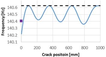
We plot in Fig. 1 the natural frequencies for the first four modes of vibration, for the healthy cantilever beam, the frequency for the beam with a crack of 1 mm depth which is removed along the beam and the natural frequencies obtained for the crack located at 0 mm.
As it can be observed from Fig. 1, the natural frequency drop due to damage located at the beam’s fixed end is smaller than the values obtained by applying Eq. (1) for all the first four weak axis vibration modes. Dissimilar, for the locations which are far enough from the fixed end, the results obtained from FEM simulation and from Eq. (1) are in good concordance.
Fig. 1Natural frequencies evolution with the damage location, compared with the frequencies of the healthy beam and the frequency drop due to the crack located at the fixed end
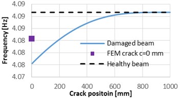
a) Mode 1
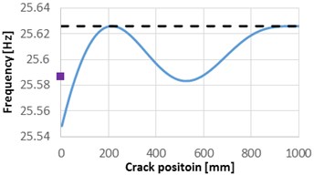
b) Mode 2
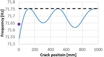
c) Mode 3
d) Mode 4
3. Materials and methods
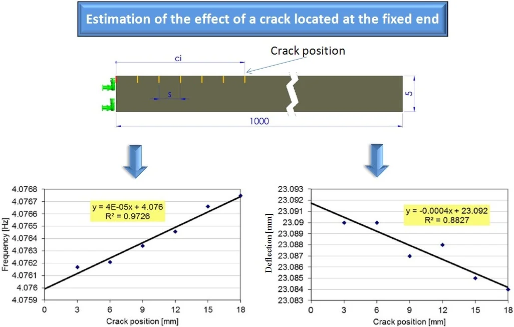
The study is carried out on a cantilever beam with length 1000 mm, width 50 and a thickness 5 mm. Both the beam and crack geometries were modeled using the computer-aided design software SolidWorks. The analysis is carried out using the engineering simulation software ANSYS. The physical-mechanical properties for the structural steel assigned for the cantilever are extracted from the ANSYS Workbench library and are presented in Table 1.
Table 1Physical-mechanical properties of the cantilever beam
Yield strength [MPa] | Ultimate strength [MPa] | Mass density [kg/mm3] | Young modulus [N/m2] | Poisson ratio [–] |
250 | 460 | 7850 | 2·1011 | 0.3 |
The damage considered here is a breathing crack, which has depth 1 mm. In the performed simulations, we first assign the crack 0 mm, i.e. at the fixed end, afterward the locations indicated in Table 2. A schematic of the beam, with a detailed view on the fixed end, and the crack positions is presented in Fig. 2. In order to obtain accurate results, for this study, we have defined a hexahedral mesh with the maximum element edge of 1 mm.
Fig. 2The geometry of the beam with transversal crack
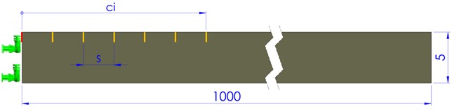
Table 2Crack positions near the fixed end of the beam
[mm] | [mm] | [mm] | [mm] | [mm] | [mm] | [mm] |
0 | 3 | 6 | 9 | 12 | 15 | 18 |
We intend to demonstrate that, if too close to the fixed end, the crack determines deflections and frequencies that do not follow the analytical solutions. This happens because the state of stress does not manifest itself around the crack as in the case it is located at a position away from the fixed end, because of the boundary.
For the mentioned crack locations, we performed modal analysis to find the first six natural frequencies for the transverse vibrations. We also targeted the stress distribution around the crack, in order to observe how the stress field is disturbed by the fixed end.
4. Frequency shift for several locations near to the fixed end
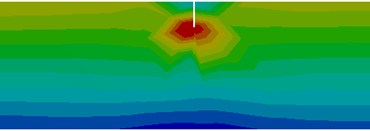
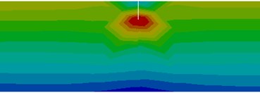
The stress distribution around the cracks located at distances is presented in Fig. 3. For the crack at the very beam end, just the beam segment to the right of the crack performs bending, so that the frequency drop due to this crack is smaller as those obtained for other locations in the vicinity of the fixed end.
This finding motivated us to obtain the frequencies for the locations where the effect of the boundary does not affect the normal beam behavior and to estimate the frequency at the fixed end from the achieved trend-line. To plot the trend-line and find the mathematical relation, we use a linear regression curve. The results in terms of frequencies of the first bending vibration mode are shown in Fig. 4. In this chart, we also indicate the mathematical relation that is used to estimate the frequency for the crack location 0 mm. Table 3 depicts the frequencies obtained by simulation for the crack at the fixed end and the estimation from the regression curve. From these results, one can observe the frequency drop is much lower for the simulation.
Fig. 3Stress distribution for the healthy beam and around the crack located at the selected positions
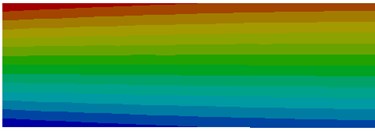
a) Healthy beam
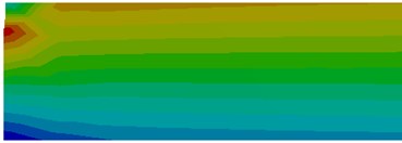
b) Crack at 0 mm
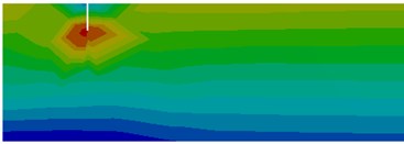
c) Crack at 3 mm
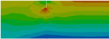
d) Crack at 6 mm
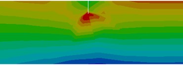
e) Crack at 9 mm
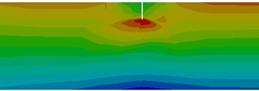
f) Crack at 12 mm
g) Crack at 15 mm
h) Crack at 18 mm
Table 3Frequencies of the cracked beam for the first vibration modes
Mode number | 1 | 2 | 3 | 4 | 5 |
Frequency [Hz] obtained directly from FEM analysis | 4.0834 | 25.586 | 71.64 | 140.40 | 232.15 |
Frequency [Hz] estimation employing the regression curve | 4.0746 | 25.539 | 71.51 | 140.15 | 231.73 |
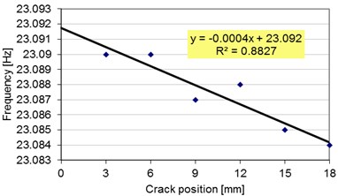
Since it is a clear link between the frequency drop and the damage severity, see Eq. (3), we expect a decrease for the deflection at the beam’s free end 0 mm. We performed simulations, by employing the static analysis module, for the beam loaded with dead mass and found the deflections for the crack locations indicated in Table 2. The values are indicated in Fig. 5. Here, also the mathematical relation for the regression curve is shown.
We calculate the deflection at the free end, i.e. 0 mm, from the achieved regression curve and indicate the obtained value in Table 4, along with the value of the deflection directly obtained from the FEM simulation.
From the results shown in Table 4, one can easily observe that the deflection due to a crack located at the fixed end differs from the estimated value. By calculating the severity with Eq. (2) by involving the estimated deflection, we obtained with Eq. (1) frequencies for the cracked beam that fit those achieved by simulation. Dissimilar, when we use deflections directly obtained from simulation we obtain wrong frequencies.
Table 4Deflections of the cracked beam’s end
Deflection obtained directly from FEM analysis [mm] | Deflection obtained from the regression curve [mm] |
23.014 | 23.092 |
Fig. 4The trend-line plotted for the frequencies of the first vibration mode of the damaged beam with different crack locations
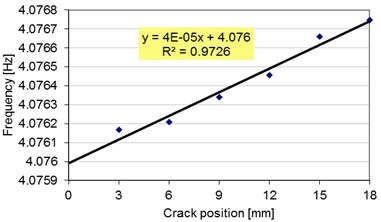
Fig. 5The trend-line plotted for the deflections of the damaged beam with different crack locations
5. Conclusions
The paper analyses how the fixed end boundary condition affect the stress distribution due to a crack. First, it is shown that the natural frequency for the beam with a crack very close located to the fixed end does not fit the trend of the frequency shift curves. Because in the theory the frequency drop for a crack located here should be the biggest, this can lead to misinterpreting of the frequency results when assessing damages. Moreover, it was found that if using the free end deflection of the beam obtained directly from FEM determines the underestimating of damage severity. Therefore, both the deflection and the natural frequency obtained by involving the regression curves plotted on the base of several points near the fixed end. This ensures a correct damage severity estimation and precise assessment of cracks in the monitored beam.
References
-
Sinha J. K., Friswell M. I., Edwards S. Simplified models for the location of cracks in beam structures using measured vibration data. Journal of Sound and Vibration, Vol. 251, Issue 1, 2002, p. 13-38.
-
Sakaris C. S., Sakellariou J. S., Fassois S. D. Vibration-based multi-site damage precise localization via the functional model based method. Procedia Engineering, Vol. 199, 2017, p. 2072-2077.
-
Gillich G. R., Gillich N., Birdeanu E. D., Iancu V. Detection of damages in simple elements. Annals of DAAAM and Proceedings of the International DAAAM Symposium, Vol. 20, 2009, p. 623-624.
-
Song Y.Z., Bowen C.R., Kim A.H., Nassehi A., Padget J., Gathercole N. Virtual visual sensors and their application in structural health monitoring. Structural Health Monitoring, Vol. 13, Issue 3, 2014, p. 251-264.
-
Chondros T. J., Dimarogonas A. D., Yao J. A continuous cracked beam vibration theory. Journal of Sound and Vibration, Vol. 215, Issue 1, 1998, p. 17-34.
-
Ostachowicz W. M., Krawczuk C. Analysis of the effect of cracks on the natural frequencies of a cantilever beam. Journal of Sound and Vibration, Vol. 150, Issue 2, 1991, p. 191-201.
-
Gillich G. R., Tufoi M., Korka Z. I., Stanciu E., Petrica A. The relations between deflection, stored energy and natural frequencies, with application in damage detection. Romanian Journal of Acoustics and Vibration, Vol. 13, Issue 2, 2016, p. 87-93.
-
Rizos P. F., Aspragathos N., Dimarogonas A. D. Identification of crack location and magnitude in a cantilever beam from the vibration modes. Journal of Sound and Vibration, Vol. 138, Issue 3, 1990, p. 381-388.
-
Worden K., Sohn H., Farrar C. R. Novelty detection in a changing environment: regression and interpolation approaches. Journal of Sound and Vibration, Vol. 258, Issue 4, 2002, p. 741-761.
-
Gillich G. R., Furdui H., Wahab M. A., Korka Z. I. A robust damage detection method based on multi-modal analysis in variable temperature conditions. Mechanical Systems and Signal Processing, Vol. 115, 2019, p. 361-379.
-
Hios J. D., Fassois S. D. A global statistical model based approach for vibration response-only damage detection under various temperatures: a proof-of-concept study. Mechanical Systems and Signal Processing, Vol. 49, Issues 1-2, 2014, p. 77-94.
-
Altunışık A. C., Okur F. Y., Kahya V. Modal parameter identification and vibration based damage detection of a multiple cracked cantilever beam. Engineering Failure Analysis, Vol. 79, 2017, p. 154-170.
-
Zhang K., Yan X. Multi-cracks identification method for cantilever beam structure with variable cross-sections based on measured natural frequency changes. Journal of Sound and Vibration, Vol. 387, 2017, p. 53-65.
-
Du Z., Chen X., Zhang H., Zi Y., Yan R. Multiple fault separation and detection by joint subspace learning for the health assessment of wind turbine gearboxes. Frontiers of Mechanical Engineering Vol. 12, Issue 3, 2017, p. 333-347.
-
Gillich G. R., Maia N. M. M., Mituletu I. C., Tufoi M., Iancu V., Korka Z. I. A new approach for severity estimation of transversal cracks in multi-layered beams. Latin American Journal of Solids and Structures, Vol. 13, Issue 8, 2016, p. 1526-1544.
-
Gillich G. R., Mituletu I. C., Praisach Z. I., Negru I., Tufoi M. Method to enhance the frequency readability for detecting incipient structural damage. Iranian Journal of Science and Technology, Transactions of Mechanical Engineering, Vol. 41, Issue 3, 2017, p. 233-242.
-
Mituletu I. C., Gillich N., Nitescu C. N., Chioncel C. P. A multi-resolution based method to precise identify the natural frequencies of beams with application in damage detection. Journal of Physics: Conference Series, Vol. 628, Issue 1, 2015, p. 012020.
-
Gillich G. R., Praisach Z. I., Iancu V., Furdui H., Negru I. Natural frequency changes due to severe corrosion in metallic structures. Strojniški vestnik – Journal of Mechanical Engineering, Vol. 61, Issue 12, 2015, p. 721-730.
-
Praisach Z. I., Minda P. F., Gillich G. R., Minda A. A. Relative frequency shift curves fitting using FEM modal analyses. Proceedings of the 4th WSEAS International Conference on Finite Differences-Finite Elements-Finite Volumes-Boundary Elements, Paris, 2011, p. 82-87.
-
Gillich G. R., Praisach Z. I., Hamat C., Gillich N., Ntakpe J. L. Crack localization in L-shaped frames. Springer Proceedings in Physics, Vol. 198, 2018, p. 315-322.
Cited by
About this article

