Abstract
In order to study the secondary bearing mechanism of weakly cemented broken surrounding rock, the surface of granite, limestone and mudstone broken rock samples were poured by cement slurry, and the weakly cemented rock mass was formed by static pressure infiltration method, and then an uniaxial loading test was carried out. The results show that the weakly cemented broken rock mass has a certain bearing capacity, but the bearing capacity is low, and the dispersion is high. The secondary bearing capacity of weakly cemented rock mass is affected by factors such as broken rock strength, rock particle size and rock gradation. The larger the rock particle size and strength are, the higher the secondary bearing capacity of the weakly cemented rock mass is. The average bearing capacity of the mudstone weak cementation specimen is 18.77 kN, and the residual bearing capacity is 1.46 kN, and a dispersion coefficient is 0.34. The average bearing capacity of granite is 343.65 kN, and the residual carrying capacity is 25.81 kN, and a dispersion coefficient is 0.11. The average bearing capacity of limestone is 367.22 kN, and the residual carrying capacity is 22.78 kN, and a dispersion coefficient is 0.3. After a certain grading, the average residual secondary bearing capacity of the weakly cemented rock mass is obviously improved, and the dispersion coefficient of peak bearing capacity is reduced. The grading scheme 1 has an average peak carrying capacity of 330.06 kN, a residual carrying capacity of 34.56 kN, and a dispersion coefficient is 0.07. The averaging scheme 2 has an average peak carrying capacity of 297.8 kN, a residual carrying capacity of 29.86 kN, and a dispersion coefficient is 0.14. The cementation regeneration mechanism of the broken rock mass mainly includes the cement-bonding effect of the cement slurry inside and on the broken rock mass. Under the loaded condition, the internal load-bearing network of the broken rock mass is the main mechanism for the secondary load of the broken rock mass, and the stability of the force-chain network is affected by the constraint. After the loss of the confinement, the force chain network fails, and the residual secondary bearing mechanism of the weakly cemented broken rock mass is transformed into the friction between the broken rock masses in the residual core rock pillar.
Highlights
- Loose broken rock mass can be cemented to form an integral structure and can have a certain secondary bearing capacity.
- Destruction of mudstone weak cementation specimens includes three modes: slurry rupture, rock mass rupture and cemented surface debonding.
- The bonding-constraining effect of cement paste is the main mechanism for the cementation regeneration of the broken rock mass.
1. Introduction
In the process of underground coal mining, weak and broken surrounding rock with high deformation, and being extremely difficult for stabilization, such as rock with broken fault zone, mining-induced broken rock in goaf and rock mass with poor cementation degree, low strength and extremely developed joints and fissures is often encountered. These surrounding rocks are easily loose and broken under strong mining disturbance, resulting in roadway instability [1, 2]. Such a surrounding rock does not have self-stability, but due to engineering needs, the instability of such surrounding rock must be controlled, to make sure that it can be self-stabilizing. In view of this kind of surrounding rock, it is usually controlled by bolting and shotcreting with wire mesh [3, 4], bolting and grouting with wire mesh [5-7], or combined bolting, grouting, shotcreting with wire mesh and steel arches support [8]. Shotcreting with wire mesh can timely seal the surface of the broken surrounding rock and improve the stress state of the surrounding rock by providing certain lateral restraints [9]. Grouting can cement the broken rock mass in the surrounding rock and improve its self-stability [10, 11]. At the same time, combined with a metal mesh, rock bolt (anchor cable), steel arches and other supporting structures, the broken surrounding rock will be bonded and restrained to form a whole, and the secondary bearing capacity of broken surrounding rock will be realized. The secondary bearing capacity of broken surrounding rock means the rock mass which has no self-stability in engineering has a certain bearing capacity again after applying a support and can keep the self-stability in a certain time [12]. The rock mass which obtains the bearing capacity again is called the secondary bearing rock mass. Improving the mechanical properties of surrounding rock and changing the stress state of surrounding rock are the main ways to realize the secondary bearing capacity of broken surrounding rock [13].
Both grouting and shotcreting can improve the mechanical properties of broken rock [14]. Ding et al. [15] found that deformation modulus, friction coefficient and rock mass strength of weakly weathered rock mass had been improved after grouting, but the cohesion had not been obviously improved. Zhao et al. [16, 17] found that the residual strength of grouting consolidation body had been greatly improved, and the deformation of rock mass had tended to be synergistic after grouting. Zhang et al. [18] compared and analyzed the mechanical characteristics of grouting body and grouting anchor body after rock sample rupture, and found that grouting cementation could have greatly improved the bearing strength of broken rock sample, but there had been no residual strength in grouting rock mass. The grouting body had obvious residual strength after anchoring. Jenifer J. Day [19] and Salimian et al. [20] studied the effects of grouting on the shear properties of rock mass fissures, rock structural planes and hard rock joints, and considered that grouting could have significantly improved the mechanical properties of structural planes. Wangxi Zhang [21] thinks that the higher the strength of rock sample and the bond strength of slurry are, the higher the strength of post-peak specimen strengthened by grouting is. Under the condition of rich water, Jinfeng Zou [22] and Guojun Wu [23] found that the slurry can activate the rock surface component to form new rock-like minerals, and the grouting effect is related to the degree of rock sample fragmentation, the density of rock sample and the bearing capacity of rock sample. Fangtian Wang [24] thinks that the strength of grouting consolidation body is affected by confining pressure, and with the increase of confining pressure, the effect of grouting reinforcement is more remarkable. Based on the statistics of the existing growth rate of grouting and solid strength of broken rock mass, R. Pan et al. [25, 26] deduced the empirical formula and made the growth theory of grouting and solid strength estimation for broken rock mass. In addition, Qingsong Zhang [5] analyzed the mechanism of grouting with the change of grouting viscosity with space, and Xing Huang [27], Deyu Qian [28] analyzed the mechanism and effect of grouting on ground surface in the broken zone.
In summary, grouting after rock mass rupture can effectively improve the strength and stiffness of the broken surrounding rock, so that the broken surrounding rock can be reshaped and can obtain the secondary bearing capacity [29, 30]. However, in the actual project, after the surrounding rock is supported by grouting or shotcreting, most of the rock mass is not fully cemented. These insufficiently cemented rock masses are between the free surface and the relatively stable inner surrounding rock. The mechanical mechanism of deformation after loading and its stress transfer mechanism are very important for the stability of the surrounding rock for the whole project. Therefore, in this paper, the cement slurry is used to incompletely bond the broken rock mass under different conditions, and the mechanical properties of such insufficiently cemented broken rock mass are discussed by the uniaxial compression test.
2. Test plan design and test
2.1. Test plan design
(1) Specimen materials: Three kinds of broken rock samples of mudstone, limestone and granite are used as cemented rock samples. The cementing medium is made of PSB32.5 Portland cement. Considering the fluidity and strength factors, the water-cement ratio of the specimen is determined to be 0.4. The mechanical parameters measured by the pure cement slurry are shown in Table 1.
(2) Test group design: a) Different lithology test groups were tested with granite, limestone and mudstone with particle sizes of 30-50 mm; b) particle sizes of the test group with different particle size were 1-10 mm, 10-20 mm, 20-30 mm, 30-50 mm when limestone is tested; c) different grading test groups are grading with limestone of 1-10 mm, 20-30 mm and 30-50 mm, grading scheme 1: the rock mass ratio of three particle sizes is 2:5:3, and the grading scheme 2: the ratio of three rock masses is 2:6:2.
(3) Preparation and maintenance of specimens: The specimens were placed several times into a mold having an inner dimension of 150 mm×150 mm×150 mm. All the specimens were prepared under the same conditions, and the prepared specimens were allowed to stand for 7 hours and then released. They are then cured for 28 days at room temperature conditions where the humidity is greater than 90 %.
(4) Loading and monitoring device: The RMT-150 rock mechanics test system is used for loading. In order to ensure uniform force on the cube test piece, a steel bearing plate of 200×200×30 mm was placed on the upper and lower ends of the test piece, and a little butter was evenly applied over the surface. High (force)-stroke loading, and force control mode were accepted, and the loading rate was 0.5 kN/s. The loading process was taken with a high-definition camera, and the thermal response of the test piece during loading was monitored by means of a FLIRSC325 infrared thermal imager.
Table 1Mechanical parameters of broken rock samples and cements
Rock sample | Bulk density / kN·m-3 | Deformation modulus / GPa | Compressive strength / MPa | Water absorption rate / % | Void ratio / % |
Grout | 18.4 | 25 | 32.73 | 2.3 | 5.5 |
Granite | 26.5 | 95 | 223.1 | 1.3 | 4.5 |
Limestone | 23.7 | 89 | 123.2 | 2.9 | 13.7 |
Mudstone | 19.2 | 15 | 25.5 | 2.6 | 6.5 |
2.2. Test specimen preparation process
(1) Pour 15 mm thick grout at the bottom of the mold, and then place a retaining ring of size 120 mm × 120 mm. The distance between the retaining ring and the mold is 15 mm.
(2) Lay a 40mm thick rock sample inside the retaining ring and level it. The cement slurry is poured in the gap of 15 mm between the retaining ring and the mold.
(3) After repeating this 3 times, remove the retaining ring and fill all the remaining 15 mm space with the cement slurry, let the cement slurry naturally soak the entire test piece, and finally smooth the upper surface.
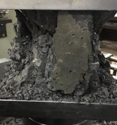
(4) Let the prepared specimens be cured, then number, and spare them. The broken rock sample and the fabricated test piece are shown in Fig. 1.
3. Weakly bonded test piece uniaxial loading test
3.1. Secondary loading failure characteristics
The uniaxial loading of the weakly cemented specimen of each test group until the test head is automatically retracted is shown in Fig. 2.
Fig. 1Broken rock sample and cemented specimens
a) Mudstone
b) Limestone
c) Granite
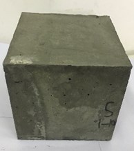
d) Cement specimen
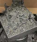
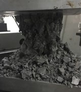
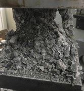
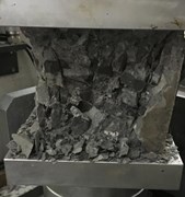
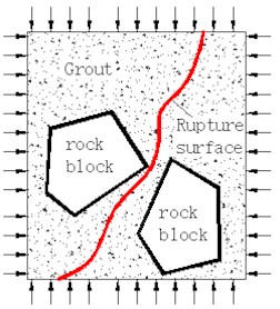
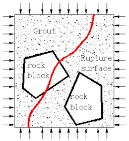
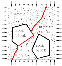
Fig. 2Destruction form of specimen in different test groups
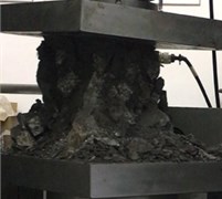
a) 30-50 mm Granite
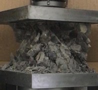
b) 30-50 mm Limestone
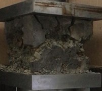
c) 30-50 mm Mudstone
d) 1-10 mm Limestone
e) 10-20 mm Limestone
f) 20-30 mm Limestone
g) 2:5:3 Gradation
(h) 2:6:2 Gradation
The granite and limestone weakly cemented specimens have local cement block peeling on the surface of the loaded test piece. When the axial force is applied to the maximum value, the cement block suddenly bulges in the middle of the test piece, and then the rock block is loose, slipping, the test piece loses its carrying capacity. The mudstone weakly cemented test piece showed surface cracking during the axial force rise stage, and no cement block peeled off. When loading to the maximum axial force, the middle part of the test piece quickly swells and falls, and the test piece clearly shows the characteristic of plastic deformation. The concept of the core rock column is proposed based on the final failure morphology of the weakly cemented broken rock mass. The physical meaning of the core rock pillar is as follows: after the weakly cemented rock mass is loaded, the structure at the two ends of the load surface is relatively continuous and stable. A rough measurement of the core rock pillar diameter of the specimen revealed that the granite core rock pillar diameter was about 60 mm, the limestone core rock pillar diameter was about 80 mm, the mudstone specimen was broken in the middle, and no continuous core rock pillar was formed. From the fracture morphology of limestone weakly cemented specimens with different particle sizes, the core rock pillars were formed in the particle size test groups of 0-10 mm, 10-20 mm, 20-30 mm and 30-50 mm. The larger the size of the rock sample is, the larger the diameter of the core rock pillar is, after the weakly cemented rock mass is loaded, that are 40 mm, 60 mm and 70 mm respectively. After loading the weakly bonded specimens of the grading test group, the residual core rock pillar diameters were 110 mm and 95 mm, respectively, which were significantly larger than the core rock pillar diameter of the single particle test group.
3.2. Secondary bearing capacity analysis
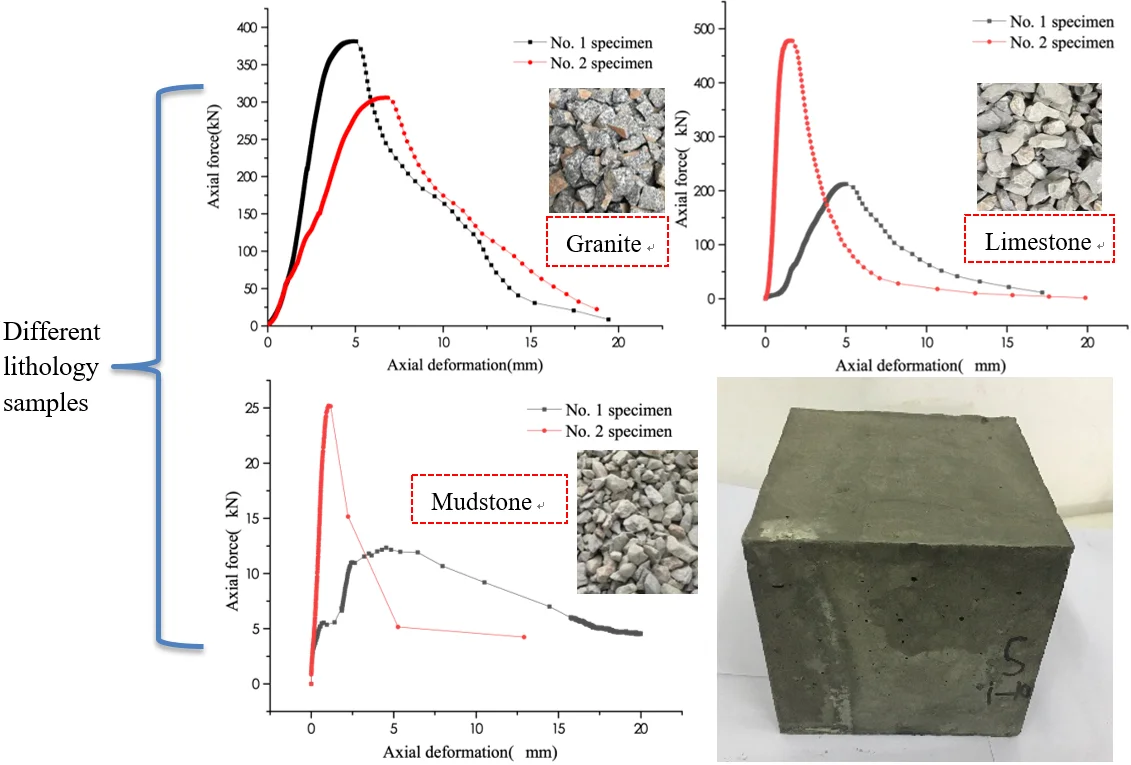
Under the condition of uniaxial loading, the variation of the secondary bearing capacity of the weakly cemented broken rock specimens of different lithology test groups is shown in Fig. 3.
Fig. 3Bearing capacity of different lithology test groups
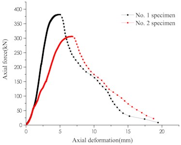
a) Granite
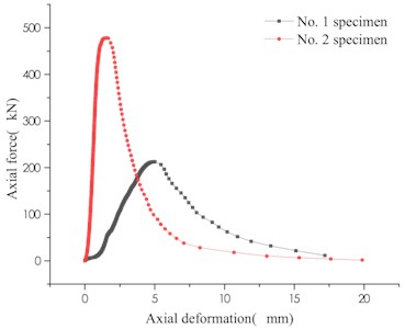
b) Limestone
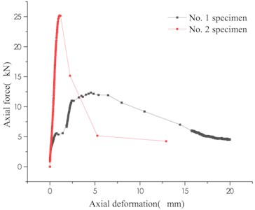
c) Mudstone
The weakly cemented specimens with different lithologies have different variation characteristics under the same loading conditions. The change trend of the bearing capacity curves of two specimens of granite and limestone is basically the same, while the mudstone changes greatly. During the gradual increase of load carrying capacity of granite and limestone, one test piece fluctuated slightly, while the axial force on the other test piece rose steadily. During the decline of load carrying capacity, a wave phase was remarkable in both granites. The fluctuation of the axial force during the loading process indicates that a slight misalignment adjustment occurs between the rock masses in the weakly cemented rock mass. The limestone weakly cemented specimens fall smoothly in the form of a negative index in the stage of decreasing bearing capacity, that is, the first rapid decline, and then gradually slow down. The mudstone specimens have two variations: before the specimen reaches the maximum load carrying capacity, the bearing capacity decreases and then rises, and when the overall behavior is plastically flowing. Test piece No. 2 has a brittle fracture characteristic that rapidly increases its load carrying capacity before it reaches its maximum load carrying capacity, and then decreases rapidly too. The variation law of the secondary bearing capacity of the specimen of different particle size test groups is shown in Fig. 4.
Different particle size test groups can be seen that the upper bearing plate of the 0-10 mm limestone test group drops beyond the maximum load capacity, and the core rock column diameter is small, resulting in the lack of subsequent bearing capacity data. The remaining secondary load carrying capacity of the remaining particle size group was measured. The change trend of the bearing capacity of specimens of the two different particle size test groups is basically the same, and the change rule of the maximum bearing capacity (from small to large particle size) is the process of first increasing, then decreasing and then increasing, and the maximum bearing capacity appears in 30-50 mm particle size group. The variation of the secondary bearing capacity of specimens of different grading test groups is shown in Fig. 5.
Fig. 4Bearing capacity of different particle size test groups
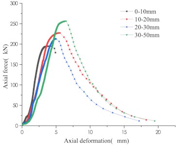
a) Test group 1
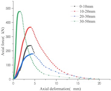
b) Test group 2
Fig. 5Bearing capacity of different grading test groups
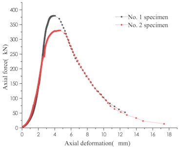
a) Gradation 2:5:3
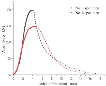
b) Gradation 2:6:3
The two grading schemes are mainly medium-sized (20-30 mm), with mass ratios of 50 % and 60 %, respectively. In Scheme 1, the mass ratio of small particle size (0-10 mm) is 20 %, and the large particle size (50-30 mm) accounts for 30 %. In Scheme 2, both the small particle size and large particle size account for 20 %. It can be seen that the variation of the secondary bearing capacity of the weakly bonded specimen after grading is basically the same, and the bearing capacity values are between the medium-sized particle size group and the large-size group. Due to the discontinuity of the internal medium, the degree of cementation of weakly cemented specimens is affected by many factors, and the value of secondary bearing capacity is highly discrete. The definition of the discrete coefficient in statistics is:
where is a discrete coefficient; is a statistic for each group; is each statistic; is the average value of each group of data.
In the actual project, most of the rock mass is in a broken state. Therefore, the bearing capacity after the surrounding rock is destroyed is worth exploring. The residual secondary bearing capacity after reaching the peak of weakly cemented rock mass can be defined as:
where , and are the peak secondary bearing capacity and the residual secondary bearing capacity respectively; and are the final deformation amount and the peak deformation amount, respectively. The data statistics of each test group are shown in Table 2.
Table 2Statistics of different test groups
Rock sample | Particle size / mm | Test piece 1. Bearing capacity / kN | Test piece 2. Bearing capacity / kN | Average peak capacity / kN | Average residual capacity / kN | Discrete coefficient / |
Granite | 30-50 | 381.44 | 305.86 | 343.65 | 25.81 | 0.11 |
Limestone | 1-10 | 194.80 | 237.40 | 216.10 | 0.00 | 0.10 |
10-20 | 227.22 | 366.82 | 297.02 | 21.21 | 0.24 | |
20-30 | 212.60 | 177.98 | 195.29 | 15.33 | 0.09 | |
30-50 | 256.46 | 477.98 | 367.22 | 22.78 | 0.30 | |
Mudstone | 30-50 | 12.34 | 25.20 | 18.77 | 1.46 | 0.34 |
Gradation 1 | 2:5:3 | 379.94 | 330.06 | 355 | 34.56 | 0.07 |
Gradation 2 | 2:6:2 | 396.42 | 297.80 | 347.11 | 29.86 | 0.14 |
The different lithology test groups (30-50 mm particle size), the mudstone weak cementation specimens have the lowest bearing capacity, the average peak load capacity is 18.77 kN, and the residual load capacity is 1.46 kN. The average peak carrying capacity of granite is 343.65 kN, and the residual carrying capacity is 25.81 kN. The average peak carrying capacity of limestone is 367.22 kN, and the residual carrying capacity is 22.78 kN. It indicates that the greater the strength of the rock sample is, the greater the secondary bearing capacity of the broken rock sample is after weak cementation. The distribution of bearing capacity values of weakly cemented specimens with the same particle size of the same rock sample is relatively discrete. Among them, the dispersion coefficient of the bearing capacity of the mudstone specimen is up to 0.34, the dispersion coefficient of the bearing capacity of the limestone specimen is 0.3, and the dispersion coefficient of the bearing capacity of the granite specimen is 0.11. Excluding the influence of human factors during the test, the mudstone softening itself is one of the reasons for the low bearing capacity and the high degree of dispersion of the weakly cemented rock mass.
The bearing capacity and dispersion coefficient of the weakly cemented specimens are affected by the particle size of the rock samples. In the different particle size test groups, the limestone weakly cemented specimens with the largest particle size have the largest secondary bearing capacity, but the degree of dispersion of the secondary bearing capacity is also high. After grading the broken rock sample, its bearing capacity is relatively stable, and the dispersion coefficient is reduced. The average peak carrying capacity of two specimens of the grading scheme 1 is 330.06 kN, the residual carrying capacity is 34.56 kN, and the dispersion coefficient is 0.07. The average peak carrying capacity of two specimens of grading scheme 2 is 297.8 kN, the residual carrying capacity is 29.86 kN, and the dispersion coefficient is 0.14. Compared with the average peak load carrying capacity of two specimens of the 30-50 mm limestone single particle size test group, the dispersion coefficient of the bearing capacity of the experimental group after grading is low. At the same time, the average residual carrying capacity has been greatly improved.
4. Analysis of secondary bearing mechanism of weak cement specimens
4.1. Breaking rock body cementation regeneration mechanism
In this project, grouting and shotcreting are used in combination with other supporting structures to restore the secondary self-bearing capacity of the extremely broken surrounding rock to a certain extent, and to achieve secondary bearing and surrounding rock stability of the broken rock mass. According to the type of support, the method of realizing the secondary bearing of broken surrounding rock can be divided into cemented medium bonding and supporting structure constraints. Further, it can be subdivided into internal bonds and constraints, and surface bonds and constraints. The metal mesh cooperates with the scaffold support to achieve surface constraint. The anchor support structure not only has an internal restraint (the bonded anchor also has a certain bonding effect) but also has a surface constraint. The internal bond and constraint of the surrounding rock are mainly applied to improve the mechanical parameters of the surrounding rock, such as cohesion and internal friction angle, to obtain the secondary bearing capacity. Surface bonding and restraint are mainly used to provide the confining pressure to the internal broken surrounding rock, so that the broken surrounding rock can obtain the secondary bearing capacity.
The crushed rock mass is poured and infiltrated by the cement slurry, so that the broken rock mass is re-bonded and constrained to form an overall structure, and the secondary bearing capacity is obtained. As the cement slurry penetrates into the internal void of the rock mass, the rock sample is not fully mixed with the cement slurry, and the internal bond of the broken rock mass is insufficient. Therefore, the produced test piece was a weak cement test piece. The structural reorganization and load-bearing capacity regeneration mechanisms of weakly cemented rock masses include internal bonding-constraining and external bonding-constraining.
(1) Internal bonding-constraining.
Inside the broken rock mass, the cement slurry acts as a cementing medium to bond the separated rock blocks together to form a rock block-cement slurry-rock block combination. When the weak cement specimen is loaded, the cement slurry produces a certain tensile, compressive and shear strength between the loose rock blocks, so that the broken rock mass can form an overall bearing structure, and a stable bearing capacity of the weak cement specimen is obtained. The bearing capacity of the rock block-cement slurry-rock block combination is mainly affected by the cement slurry, rock mass, cemented surface strengths. Among them, the strength of cement slurry is related to cementing material, water-cement ratio and maintenance conditions. The strength of the rock mass is related to the rock lithology, rock mass and rock block irregularity coefficient. The bonding strength of the cementing surface is related to the roughness of the rock surface, the area of the cemented surface, and the strength ratio of the cement to the rock mass.
(2) External bonding-constraining.
A certain thickness (about 15 mm) of cement slurry is placed on the surface of the broken rock mass to wrap the broken rock mass. When the weak cement is axially loaded, the “shell” formed by the cement slurry will provide a certain lateral constraint, which is equivalent to providing a confining pressure to restrict the lateral expansion deformation of the broken rock mass and to maintain the stability of the internal load-bearing structure of the broken rock mass to a certain extent. After the lateral restraint fails, the overall load-bearing structure inside the broken rock mass will be destroyed quickly. The lateral constraint is related to the cement strength and thickness. At the same time, the wrapped cement slurry will penetrate and bond a certain range of rock mass on the surface of the broken rock mass, and improve the anti-deformation ability of the surface of the broken rock mass.
4.2. Secondary bearing and failure mechanism of weak cement
(1) Bearing mechanism of weakly cemented broken rock mass.
Due to the weak degree of cementation, after the cement body is deformed by loading, the internal structure of the broken rock mass will form a force chain structure similar to the granular material of the bulk [31]. A plurality of force chains is interconnected to form a force chain network throughout the test piece for transmitting and carrying external loads. Among them, the path that transmits the higher load is called the strong chain, and the path that transmits the lower load is called the weak chain [32]. The force chain network is not stable, but is constantly evolving with loading conditions and the carrying capacity of the blocks. The maximum load that the force chain network can transmit as a whole is the maximum secondary load capacity of the weakly cemented broken rock mass. Therefore, maintaining the stability of the force chain network structure can effectively improve the secondary bearing capacity of the broken rock mass as a whole.
There are two conditions for the formation of a force chain network. First, the adhesion between particles is weak, and secondly, a constraint is available. The weakly cemented rock body itself has a weak degree of cementation. At the same time, a certain thickness of cement slurry is bound on the surface of the broken rock mass, which can basically meet the conditions for forming the force chain bearing. Under the constraint conditions, the bearing capacity of the broken rock mass mainly depends on the compression strength of the rock mass on the force chain network, the friction strength between the rock blocks and the confinement constraint strength.
Under the condition of strong confinement constraint, the crushed rock sample will be crushed against the core and eccentricity [17]. However, under weak lateral conditions, the rock block does not necessarily undergo crushing damage. Due to the irregularity of the rock block, the contact form and the contact area are different during the loading process. The compressive strength of the rock mass in the force chain network can only be obtained based on the statistical theory [33]:
where is the rock mass strength in the statistical sense; is the apparent damage strength of the particle size of particles, which can be measured by experiments; is the fractal dimension of the rock block, the value range is 2.0-3.0; is the number of rock blocks.
When the strength of the cement slurry is less than the strength of the rock mass, under weak cementation conditions, that is, there is little cement slurry between the two rock blocks, or when the cementation thickness is very thin. The cement slurry is equivalent to filling between the two rock blocks. Therefore, the frictional strength between the rock blocks can be referenced to the shear strength of the structural surface with the filling material and statistically averaged:
where is the shear strength of the cemented surface; is the normal stress on the cemented surface; is the roughness coefficient of the cemented surface; is the compressive strength of the rock mass or cementing medium (taking the value of the lower compressive strength); is the basic friction angle of the cemented surface; is the peak shear angle; is the peak shear strength of the cemented surface.
When the strength of the cement slurry is greater than the strength of the rock mass, or the rock mass is softened by water, the rock mass and the cement slurry exhibit plastic deformation characteristics similar to those of the soil, and there is no obvious peak bearing capacity (such as the mudstone No. 1 test piece). Under weak cementation conditions, the mudstone is not fully in contact with water or cement slurry, and some mudstone rock blocks can still form a force chain network bearing, which may produce the peak bearing capacity and then quickly lose the bearing capacity (such as mudstone No. 2 test piece).
(2) Weakly cemented rock mass failure mechanism.
Due to the difference in the strength of the broken rock sample and water softening, the secondary bearing capacity of the weakly cemented rock mass is mainly determined by the strength of the rock mass, the strength of the cementing medium and the strength of the cemented interface. In the secondary load-bearing process, three failure modes will be generated inside the weakly cemented broken rock mass, as shown in Fig. 7.
Fig. 7Internal failure mode of cemented broken rock mass
a) Slurry rupture
b) Rock block rupture
c) Cemented surface rupture
According to the test, the above three failure modes may occur during the destruction process of the mudstone weak cementation specimen. In the process of bearing the limestone and granite weak cementation specimens, the slurry rupture and interface debonding failure modes were dominant.
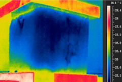
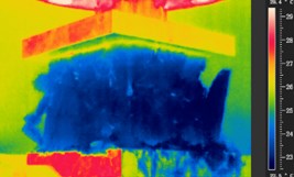
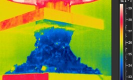
The weakly cemented specimens of the broken rock samples are discontinuous inside, and the compression failure process includes two forms of bond failure and friction failure, which are accompanied by changes in the heat of the test piece. Therefore, the heat change and the overall damage process during loading the test piece are monitored by FLIRSC325 Infrared Thermal Imager, and the results are shown in Fig. 8.
Fig. 8The change of seed heat during the failure process
a) Partial exfoliation
b) Surface bulging
c) Rock pillar formation
The heat mode of the test piece is not changed significantly before the cement slurry wrap is destroyed. After the cement slurry wraps off, multiple “hot spots” appear on the rock pillar during the formation of the core rock pillar. These “hot spots” are the heat generated by the friction between the blocks. It can be inferred that before the surface constraint fails, the cement-bonding-constraining effect of the cement slurry in the weakly cemented broken rock specimens, the frictional displacement between the rock masses is less, and a stable bearing structure with better integrity can be formed (force chain network). After the surface constraint fails, the load-bearing structure in the specimen is broken, and the secondary bearing capacity after the failure is provided by the frictional strength between the rock blocks in the residual core rock column. During the load-bearing process, due to frictional displacement, heat is generated, and multiple “hot spots” are formed on the core rock pillar. Therefore, the overall failure process of the weakly cemented broken rock specimen can be summarized into two stages: the secondary load-bearing stage and the residual secondary load-bearing stage of the broken rock mass.
The stage before the test piece reaches the peak load is the main secondary load stage of the weakly cemented broken rock mass. In this stage, the cement slurry wrapping layer on the surface of the test piece constrains the weakly cemented broken rock mass from forming a force chain network, and the cement slurry wrapping layer itself forms a frame-type load-bearing structure to carry jointly the external load. The secondary load-carrying capacity of the test piece increases rapidly as the axial deformation increases. When the axial force increases to a certain extent, due to the dense texture of the cement slurry coating on the surface of the test piece, the overall elastic modulus becomes significantly higher than the elastic modulus of the internal weakly cemented broken rock mass, and the deformation is uncoordinated, resulting in partial peeling of the cement slurry coating to accommodate the overall deformation of the test piece. At this time, the test piece does not have a significant heat change. When the axial force is close to the maximum load capacity of the test piece, a large amount of elastic energy is accumulated in the coating layer of the cement slurry, and the internal weakly cemented broken rock body produces a high lateral extrusion, so that the test piece is rapidly blasted and broken, and the surface layer is broken. The fracture rock mass of the outer layer is loose. The internal weakly cemented rock mass loses the lateral constraint, the bearing capacity of the test piece decreases rapidly, and the test piece enters the residual secondary load bearing stage. After the specimen with high strength of rock block is destroyed, the core rock pillar is formed, and the weakly cemented specimen with low strength of rock mass is subjected to compression shear failure and extrusion bulging damage. In the residual secondary load-bearing stage, the test piece carries the external load by the extrusion friction of the rock mass in the core rock column, and the extrusion friction between the rock blocks produces a “hot spot”. In this stage, the overall bearing capacity of the broken rock mass is low.
5. Conclusions
1) After cementing a broken rock mass with cement slurry, the original loose broken rock mass can be cemented to form an integral structure and can have a certain secondary bearing capacity, but the bearing capacity is low, and the discrete coefficient is high. The variation of bearing capacity varies with the strength, particle size and gradation of rock sample.
2) For different rock samples, the greater the strength of the rock sample is, the greater the secondary bearing capacity of the cementation body is. The larger the rock sample size is, the larger the diameter of the core rock column is after the test piece is destroyed. The discrete coefficient of the bearing capacity of the cement specimens after a certain gradation is reduced, and the residual secondary bearing capacity after the failure is larger.
3) Destruction of mudstone weak cementation specimens includes three modes: slurry rupture, rock mass rupture and cemented surface debonding. The damage of limestone and granite specimens is dominated by slurry rupture and cemented surface debonding.
4) The bonding-constraining effect of cement paste is the main mechanism for the cementation regeneration of the broken rock mass. In the main stage of the secondary bearing of the weakly cemented rock mass, the common bearing capacity of the force chain network and the surface cement slurry wrap box-type bearing structure under the weak lateral constraint is the main bearing mechanism. In the residual secondary load-bearing stage, the squeeze friction between the weakly cemented broken rock mass in the core rock column is the main mechanism of secondary bearing.
Through the test, it can be recognized that in the extremely broken engineering rock mass support, the insufficiently cemented broken rock mass between the free surface and the inner surrounding rock transmits the external load in the form of a force chain network under certain confinement conditions (equivalent to transmitting support resistance). Only when the lateral restraint is high, and has a certain resistance to deformation, although the force chain network structure inside the broken rock mass will continue to evolve, it can also transmit the supporting load to provide the confining pressure to the deeper surrounding rock, giving full play to the self-supporting capacity of the surrounding rock, thus maintaining the stability of the surrounding rock as a whole. The evolution law of the internal force chain network of the broken rock mass, and the influence of the lateral restraint force on the internal force chain network of the broken rock mass needs a further study.
References
-
He M. Latest progress of soft rock mechanics and engineering in China. Journal of Rock Mechanics and Geotechnical Engineering, Vol. 6, Issue 3, 2014, p. 165-179.
-
Wang H., Jiang Y., Xue S., et al. Influence of fault slip on mining-induced pressure and optimization of roadway support design in fault-influenced zone. Journal of Rock Mechanics and Geotechnical Engineering, Vol. 8, Issue 5, 2016, p. 660-671.
-
Yang Shengqi, Miao Chen, Jing Hongwen, et al. Case study on large deformation failure mechanism of deep soft rock roadway in Xin’An coal mine, China. Engineering Geology, Vol. 217, 2017, p. 89-101.
-
Shen B. Coal mine roadway stability in soft rock: a case study. Rock Mechanics and Rock Engineering, Vol. 47, Issue 6, 2014, p. 2225-2238.
-
Zhang Q., Zhang L., Liu R., et al. Grouting mechanism of quick setting slurry in rock fissure with consideration of viscosity variation with space. Tunnelling and Underground Space Technology, Vol. 70, 2017, p. 262-273.
-
Zhang D. M., Huang Z. K., Wang R. L., et al. Grouting-based treatment of tunnel settlement: Practice in Shanghai. Tunnelling and Underground Space Technology, Vol. 80, 2018, p. 181-196.
-
Jin-Long L., Hamza O., Davies Vollum K.-S., et al. Repairing a shield tunnel damaged by secondary grouting. Tunnelling and Underground Space Technology, Vol. 80, 2018, p. 313-321.
-
Guo P., He M., Wang J. Study on coupling support technique in the roadway of Hecaogou No. 2 coal mine with soft roadway of large deformation. Geotechnical and Geological Engineering, Vol. 36, Issue 2, 2018, p. 1161-1173.
-
Yang J. M., Kim J. K., Yoo D. Y. Performance of shotcrete containing amorphous fibers for tunnel applications. Tunnelling and Underground Space Technology, Vol. 64, 2017, p. 85-94.
-
Lu G., Wang Y. S., Zhang Y., et al. Feasibility of using sodium silicate as grouting in loose coal bed sections for methane drainage. Tunnelling and Underground Space Technology, Vol. 72, 2018, p. 107-113.
-
Qian D., Zhang N., Zhang M., et al. Application and evaluation of ground surface pre-grouting reinforcement for 800-m-deep underground opening through large fault zones. Arabian Journal of Geosciences, Vol. 10, Issue 13, 2017, p. 285.
-
Wang P, Yu W J, Feng T, et al. Experimental study on second diagenesis by compaction and consolidation of soft and broken rock, Chinese Journal of Rock Mechanics and Engineering, Vol. 37, Issue 8, 2018, p. 1884-1895, (in Chinese).
-
Wu Q. H., Weng L., Zhao Y. L., et al. On the tensile mechanical characteristics of fine-grained granite after heating/cooling treatments with different cooling rates. Engineering Geology, Vol. 253, 2019, p. 94-110.
-
Wu Q. H., Li X. B., Weng L., et al. Experimental investigation of the dynamic response of prestressed rockbolt by using an SHPB-based rockbolt test system. Tunnelling and Underground Space Technology, Vol. 93, 2019, p. 103088.
-
Ding Z. W., Qiu H. F. Experimental Research on New Grouting Reinforcement Technology of Roadways with Fractured Surrounding Rock. Chinese Journal of Underground Space and Engineering, Vol. 12, Issue 4, 2016, p. 958-962, (in Chinese).
-
Zhao Y., Tang J., Chen Y., et al. Hydromechanical coupling tests for mechanical and permeability characteristics of fractured limestone in complete stress-strain process. Environmental Earth Sciences, Vol. 76, Issue 1, 2017, p. 24.
-
Zhao Y., Wang Y., Wang W., et al. Modeling of rheological fracture behavior of rock cracks subjected to hydraulic pressure and far field stresses. Theoretical and Applied Fracture Mechanics, Vol. 101, 2019, p. 59-66.
-
Zhang J. P., Liu L. M., Li Q. H., et al. Development of cement-based self-stress composite grouting material for reinforcing rock mass and engineering application. Construction and Building Materials, Vol. 201, 2019, p. 314-327.
-
Day J. J., Diederichs M. S., Hutchinson D. J. New direct shear testing protocols and analyses for fractures and healed intrablock rockmass discontinuities. Engineering Geology, Vol. 229, 2017, p. 53-72.
-
Salimian M. H., Baghbanan A., Hashemolhosseini H., et al. Effect of grouting on shear behavior of rock joint. International Journal of Rock Mechanics and Mining Sciences, Vol. 98, 2017, p. 159-166.
-
Zhang W., He C., Zhang J., et al. Mechanical behavior of post-fire half-grouted sleeve connection covered by concrete. Construction and Building Materials, Vol. 201, 2019, p. 218-231.
-
Jin-Feng Z., Peng-Hao Z. Analytical model of fully grouted bolts in pull-out tests and in situ rock masses. International Journal of Rock Mechanics and Mining Sciences, Vol. 113, 2019, p. 278-294.
-
Wu G., Jia S., Chen W., et al. An anchorage experimental study on supporting a roadway in steeply inclined geological formations. Tunnelling and Underground Space Technology, Vol. 82, 2018, p. 125-134.
-
Fangtian W., Cun Z., Shuaifeng W., et al. Whole section anchor–grouting reinforcement technology and its application in underground roadways with loose and fractured surrounding rock. Tunnelling and Underground Space Technology, Vol. 51, 2016, p. 133-143.
-
Pan R., Wang Q., Jiang B., et al. Failure of bolt support and experimental study on the parameters of bolt-grouting for supporting the roadways in deep coal seam. Engineering Failure Analysis, Vol. 80, 2017, p. 218-233.
-
Zhao Y., Zhang L., Wang W., et al. Creep behavior of intact and cracked limestone under multi-level loading and unloading cycles. Rock Mechanics and Rock Engineering, Vol. 50, Issue 6, 2017, p. 1409-1424.
-
Huang X., Liu Q., Shi K., et al. Application and prospect of hard rock TBM for deep roadway construction in coal mines. Tunnelling and Underground Space Technology, Vol. 73, 2018, p. 105-126.
-
Wu Q. H., Chen L., Shen B. T., et al. Experimental investigation on rockbolt performance under the tension load. Rock Mechanics and Rock Engineering, Vol. 52, Issue 11, 2019, p. 4605-461.
-
Zhao Y., Wang Y., Wang W., et al. Modeling of non-linear rheological behavior of hard rock using triaxial rheological experiment. International Journal of Rock Mechanics and Mining Sciences, Vol. 93, 2017, p. 66-75.
-
Zhao Y., Luo S., Wang Y., et al. Numerical analysis of karst water inrush and a criterion for establishing the width of water-resistant rock pillars. Mine Water and the Environment, Vol. 36, Issue 4, 2017, p. 508-519.
-
Liu C., Sun Q., Jin F., et al. A fully coupled hydro-mechanical material point method for saturated dense granular materials. Powder technology, Vol. 314, 2017, p. 110-120.
-
Liu C., Sun Q., Jin F. Structural signature of a sheared granular flow. Powder Technology, Vol. 288, 2016, p. 55-64.
-
Zhao Y., Zhang L., Wang W., et al. Cracking and stress-strain behavior of rock-like material containing two flaws under uniaxial compression. Rock Mechanics and Rock Engineering, Vol. 49, Issue 7, 2016, p. 2665-2687.
About this article

This work was supported by the National Natural Science Foundation of China (Grant Nos. 51804114, 51774130, 51974117), the project funded by the Research Fund of State and Local Joint Engineering Laboratory for Gas Drainage & Ground Control of Deep Mines (Henan Polytechnic University) (SJF201806), funded by the Open Research Fund Program of Work Safety Key Lab on Prevention and Control of Gas and Roof Disasters for Southern Coal Mines, Hunan University of Science and Technology (E21828), and funded supported by the Postdoctoral Research Foundation of Hunan University of Science and Technology (E61803).
