Abstract
This paper presents the refined technique of dynamic calculations for suspension earthquake-resistant building. The improved design schemes of suspension buildings and structures have been demonstrated. Two versions of suspension buildings have been analysed. For the system with the building as a point mass suspension on the fixed bearing frame thread, a system of Lagrange differential equations of the second kind has been derived. For the building presented as a rigid rod with the length equal to its height, also suspended on the supporting frame, the solution is performed using principles of dynamic calculations and methods of theoretical mechanics. It has been demonstrated, that the horizontal force in the suspension building is ten times less than the force in a traditional cantilever building, and that for the real horizontal stiffness of the supporting frame the dynamic strains are far from resonant values. The possibility of adjusting dynamic forces by regulating the stiffness of the supporting frame, length of the thread of suspension and other parameters. The proposed calculation schemes are useful for the preliminary calculations, and the finite design of the suspension building can be performed in modern software packages (e.g., Ansys, Abacus, etc.).
1. Introduction
The most dangerous component of the acting forces during an earthquake is the horizontal component. In dynamic calculations, the masses of the floors are concentrated at slab levels [1]. Horizontal seismic forces on each floor are known to be equal to the product of the mass and acceleration of the ground vibration. Herewith, the greater the number of floors the building has, the larger the stresses are that will develop at the foundation level.
The existing systems for seismic isolation of buildings are traditionally performed with the use of damping devices, disconnecting constrains, etc. [1-9]. There are buildings in which a massive pendulum with a spring system is suspended as a dynamic vibration absorber (for example, the Taipei 101 in China). Meanwhile, the dynamic strains still remain quite high. Furthermore, such seismic protection mechanisms are rather expensive.
Preliminary studies demonstrate the effectiveness of suspension of the building itself. Thus, the seismic strains can be significantly reduced. Due to the unusual suspension of the building, its design features, as well as the approach to calculation of strength and deformability, must be subjected to careful examination and justification. Advantages of such a construction are obvious, but the technique for the calculation of dynamic strains requires improvement.
Hence, the purpose of this paper is to improve the dynamic design scheme of suspension building in order to refine the calculated dynamic strains.
2. The dynamic scheme for the suspension building
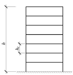
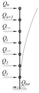
For the cantilever building, during the oscillation of the foundation with the acceleration the horizontal dynamic forces develop at the level of each overlap, where is the mass of the th floor (Fig. 1).
Let the height of the floors is equal, the number of the floors is , and the total height of the building is equal to . Then at the foundation level the total horizontal force , which is maximum shear force for the columns of the first floor, as well as the total bending moment at the base will be determined by the known formula (Eq. (1)):
The proposed building is suspended on the bearing frame, the mass of which is much less than the mass of the building itself. Estimations are performed with the help of Lagrange equations of the second kind [3, 10]. Herewith the building is considered as a single-mass system (the whole building as a unit) or as a multi-mass system (each floor has its own mass) [1]. Various schemes are discussed during preliminary calculations: the pendulum with the oscillating suspension point; one mass or several masses suspended on the frame, the base of which is subjected to kinematic disturbances [11].
The geometric and dynamic calculation scheme of the proposed suspension building is presented in Fig. 2.
Fig. 1The scheme of the cantilever five-storey building: a) geometric scheme, b) dynamic calculation scheme
a)
b)
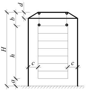
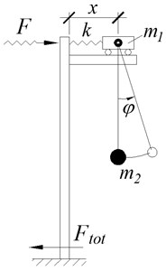
Fig. 2Scheme of the suspension fifteen-storey building: a) geometric scheme, b) dynamic calculation scheme
a)
b)
The essence of the scheme of the suspension building is in hanging of the building to the base frame by cables. The frame is wider than the building on the value of 2. With the purpose to suspend the building vertically, the inclined part of the height is planned in the upper part of the frame. The vertical arrangement of the cables is necessary in order to prevent the vertical component of the force for the horizontal oscillation of the basement during an earthquake. There is a gap in the lower part between the floor of the first floor and the ground (see Fig. 2(b)). The length of the cables , on which the building is suspended, should be selected by calculation for regulatory forces to the support frame, the frequency and period of oscillation of the building during an earthquake.
The dynamic calculation scheme (see Fig. 2(b) is presented as a trolley of mass , attached by a spring of stiffness to the upper part of the inverted L-shaped frame. Its pillar and girder have infinite stiffness. The trolley is free to move without friction on the girder of the inverted L-shaped frame. The mass is suspended to the trolley by the flexible inextensible thread, where is the concentrated mass of the whole building. The spring stiffness is determined from the condition of equality of the displacement of the spring from a single horizontal force to the displacement of the top of the supporting frame of height from the same unit force the (see Fig. 2(a)).
During horizontal oscillation of the base the distance between the trolley axis and the point fixing to the rigid frame will change. The value of the dynamic force applied to the top of the frame will be determined from the obvious expression . At the Foundation the maximum value of the shear force and the bending moment will be determined from the obvious expressions (Eq. (2)):
where is the maximum value of displacement of the trolley relatively to the support (see Fig. 2(b)).
If from the solution of the dynamic problem the functions and are solved (where is time), then the maximum value of the dynamic force can be easily determined by Eq. (2), by finding the value .
In order to compare the values and with the values and the calculations by two different dynamic schemes should be conducted (accordingly to the Fig. 1(b) and 2(b)).
The values and can be easily determined directly from Eq. (1). Finding of the values and require the solution of the problem of dynamics first, which is better to perform using the Lagrange equations of the second kind. In this case displacement of the trolley and rotation angle of the suspension thread are accepted for the generalized coordinates. The system of Lagrange equations of the second kind has been developed for such a task by the authors:
The values denoted in the Eq. (3): , are the values of mass of the trolley simulating the mass of the supporting frame (position 3 in Fig. 2(a)), and the mass of the suspension building itself accordingly; is the length of the suspension of the building (approximately can be taken equal to the distance in Fig. 2(a)); is the free fall acceleration; , are the amplitude and frequency of oscillation of the ground, respectively (vibrations of the grounds are taken by the law ); dot or two dots over a symbol indicate the first or the second time derivative, respectively.
The solution of the system of differential Eq. (3) is not difficult, which is the advantage of the proposed approach. The fact that, by this approximate scheme many preliminary calculations can be performed (requiring quite little effort and time). On the basis of these evaluations the acceptable design of the supporting frame, suspension and other parameters can be selected. After estimation of the constructive scheme, the final calculation for strength, stability and deformability can be conducted using widespread software packages such as Ansys, Abacus etc.
3. Comparison of the suspension building with the cantilever building
The advantages of preliminary analysis of the structural system by the proposed approximate calculation technique reveal at selection of the horizontal stiffness of the supporting frame. The example of analysis of the structural system of the multi-storey framed buildings is considered below. Let there is a suspension fifteen-story building, which dimensions in plan are 12×12 m and the storey height is 3.5 m. The total mass per square meter of the overlap is 750 kg/m2, including the mass of the columns, ceiling structure, etc. Then the total mass of the building is 1612 t. The height of the frame with respect to the sizes and in Fig. 2 is 60 m, its dimensions in plan are 13×13 m, considering openings (Fig. 2(a)). Let the length of the suspension thread is 5 m. A simple static calculation of the supporting frame results the requirements for the sufficient sections. The steel pipes with a diameter of 550 mm and a wall thickness of 10 mm can be accepted for the columns. In order to reduce the effective length of the columns, the struts are provided every 15 m by the height of the strut along the perimeter of the frame, as the pipes of diameter 550 mm and wall thickness of 6 mm. Then the mass of the supporting frame is approximately 41.5 t. The stiffness coefficient in the horizontal direction of such a frame (the conditional stiffness of the spring according to the diagram of Fig. 2(b)) is equal to 136300 N/m.
The system of Eq. (3) is used for the computation. Calculation is conducted for the acceleration of the ground vibration 4.8 m/s2, which corresponds to the maximum value for the earthquake of 9 points. For this acceleration the ultimate amplitude and frequency of oscillation 0.048 m, 10 Hz (an example for other frequency and amplitude is considered below).
In the result of the calculation for the system of Eq. (3) the maximum horizontal displacement 0.144 m is obtained. After the substitution in (2) it gives the value of the maximum dynamic horizontal force 41 kN. And the value of the maximum force for the cantilever building according to the Eq. (1) is equal to 7737 kN which is 188 times more.
Now the approach to analysis the structural system of the suspension building by using the above technique is considered. Varying the value of stiffness coefficient for the frame results in changing efforts . So, for the above example by varying the stiffness coefficient when solving the system of Eq. (3), the dependence table for from has been obtained (see Table 1).
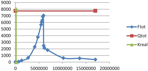
The graph of dependence is presented in Fig. 3 in the whole range of stiffness values, for which the system of Eq. (3) was solved.
Fig. 3Graph of the dependence Ftotk in the whole range of stiffness, for which the system of Eq. (3) has been solved
The graph of dependence in the range of real stiffness is demonstrated in Fig. 4.
According to the Table 1 and Fig. 4, in the range of real stiffness of the supporting frame the ultimate horizontal dynamic force is significantly less than the force in the cantilever building, which evidence in favor of the proposed construction of the suspension building.
Fig. 4Graph of the dependence Ftotk in the range of real stiffness, for which the system of Eq. (3) has been solved
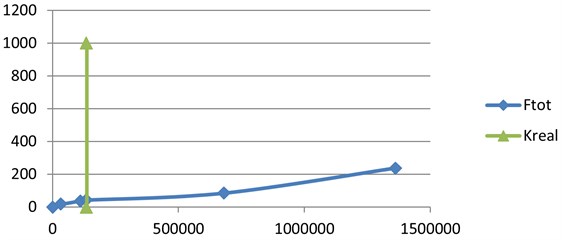
Table 1Dependence of the dynamic force from the stiffness coefficient
# | [N/m] | [m] | [kN] | Comment |
1 | 35000 | 0.445 | 15.6 | – |
2 | 110800 | 0.329 | 36.5 | – |
3 | 136300 | 0.307 | 41.9 | The real stiffness in the considered example |
4 | 681500 | 0.124 | 84.5 | – |
5 | 1363000 | 0.175 | 238 | – |
6 | 2726000 | 0.241 | 657 | The area closed to the resonance when the stiffness vary from 10· to 75· |
7 | 4089000 | 0.565 | 2310 | |
8 | 4770500 | 0.794 | 3788 | |
9 | 5452000 | 1.035 | 5643 | |
10 | 5588300 | 1.08 | 6035 | |
11 | 5724600 | 1.10 | 6331 | |
12 | 5860900 | 1.172 | 6869 | |
13 | 5935865 | 1.185 | 7034 | |
14 | 5997200 | 0.411 | 2465 | |
15 | 6133500 | 0.346 | 2122 | |
16 | 6815000 | 0.27 | 1840 | |
17 | 10222500 | 0.061 | 623 | |
18 | 13630000 | 0.042 | 572 | |
19 | 17037500 | 0.022 | 375 |
The Fig. 3 demonstrate, that in the range of stiffness from 10 till 75 the force increases to large values (i.e. this is the area of the resonant values). The real (basic) stiffness of the supporting frame was obtained from the static calculation (see above). However, even in the range of resonant stiffness the force is only approaching the value of .
The foregoing technique allows to find such horizontal stiffness of the supporting frame for every special case of the suspension building, so that the dynamic forces were far from resonance values. Moreover, for the frame’s structure of the sufficient bearing capacity and stiffness its horizontal stiffness can be simply changed within wide limits, for example, by considering or, conversely, neglecting of certain inclined bars (struts). The horizontal dynamic forces to the frame, period and the oscillation frequency of the building can also be changed by varying the length of the building’s suspension thread.
For other values of amplitude and frequency of oscillation of the ground the values of change, but for values of the real stiffness of the supporting frame (for the considered example) remain significantly smaller than the values of the horizontal dynamic forces in traditional cantilever building (Fig. 1). For example, when the values of amplitude and frequency are 0.48 m, 1 Hz for the basic stiffness of the frame ( 136300 N/m) solution of the system of equations (3) results 178 kN, which is also less than the value of 774 kN for acceleration, which in this case is 0.48 m/s2. However, the value 1.308 m. Such an oscillation is impermissible, so in that case the stiffness of the frame should be increased. For the stiffness 10· 1363000 N/m the ultimate deviation is a valid value 0.045 m, and the dynamic force of the value 61 kN is considerably less than the force 774 kN.
It has been demonstrated, that the proposed approximate dynamic calculation scheme can be used for the preliminary calculation and selection of design scheme of the supporting frame of the suspension building, which allows analysis of the structural system and significantly simplifies the calculations. The dynamic forces acting on the bearing frame, as seen from the above example, are much smaller than for the case when the columns of the building frame are fixed in the foundation. Furthermore, in order to exclude resonance phenomena during an earthquake, the dynamic force, frequency and period of oscillation of the suspension building can be controlled by varying the horizontal stiffness of the supporting frame, by changing the length of the suspension thread, by installing metal bars or springs in the bottom of the suspension buildings, as well as by variation the ratio of masses of the frame and the building.
After determining the preliminary design sections of the supporting frame (in the result of the dynamic estimation described above) and the suspension building itself, the final seismic analysis can be performed using known software systems such as Ansys, Abacus, Nastran, etc.
The conducted calculations show that the horizontal component of the dynamic force to the support frame of the suspension building is many times less than the similar force to the traditional cantilever building. In addition, unlike the protection systems with the disconnected constrains, the proposed system does not require replacement of any constructures or structural elements after the earthquake.
Under the action of the wind loads dynamic forces in the elements of the proposed building will also be significantly less. Thus, implementation of the proposed suspension building on the one hand significantly increases its seismic safety, on the other hand does not increases the construction costs.
4. Conclusions
An analysis of the proposed suspension buildings has been conducted in this paper. The benefits of suspension buildings have been demonstrated in comparison to the traditional cantilever buildings. The essential advantage is the significant reduction of seismic forces. The improved design schemes of the suspension buildings and structures have been shown, and the system of Lagrange differential equations of the second kind has been derived for them. On the basis of these calculation schemes, the possibility for dynamic analysis of suspension buildings has been shown, as well as the possibility for regulating the efforts that arise due to an earthquake by varying the change in the horizontal stiffness of the supporting frame, the length of the suspension thread, etc. It has been proved that increasing the vibration amplitude with a simultaneous decrease in frequency lead to an increase in the dynamic forces, which will still much be less in the scheme of suspension building than in cantilever building.
This paper presents the proposed scheme of suspension building, which is useful for the preliminary calculation and selection of bearing structures and the analysis of their dynamic forces. Such estimations are not very time-consuming, and the finite design of the suspension building can finished in widespread software packages (e.g., Ansys, Abacus, etc.).
References
-
Eurocode 8: Seismic Design of Buildings Worked examples. European Commission, 2012, https://eurocodes.jrc.ec.europa.eu/doc/WS_335/report/EC8_Seismic_Design_of_Buildings-Worked_examples.pdf.
-
Chang C. C. Mass dampers and their optimal designs for building vibration control. Engineering Structures, Vol. 21, Issue 5, 1999, p. 454-463.
-
Eisenberg Y. Constructions with Disconnective Constraints for Seismic Areas. Construction Publishing House, Moscow, 1976.
-
Hamburger R. O. Facts for Steel Buildings Number 3 - Earthquakes and Seismic Design. 2009, https://www.aisc.org/globalassets/aisc/publications/facts-for-steel-buildings-3-earthquakes-and-seismic-design.pdf.
-
Moon K. S. Structural design of double skin facades as damping devices for tall buildings. Procedia Engineering, Vol. 14, 2011, p. 1351-1358.
-
Yablonskij A. A. Course of Theoretical Mechanics. Part II. Dynamics. Moscow, 1966.
-
Anti-seismic devices. European code 15129:2009. European Committee for Standardization (CEN), Italian Standardization Institute (UNI EN), Brussels, Belgium, 2009.
-
Castellano M. G., Infanti S. Recent applications of Italian anti-seismic devices. Earthquake Resistant Engineering Structures/WIT Transactions on The Built Environment, Vol. 104, 2009, p. 333-342.
-
Szefer G., Mikulski L., Laskowski H. Optimal vibrations of active structures achieved by pendulum actuators. 6th World Congress of Structural and Multidisciplinary Optimization, Rio de Janeiro, 2005.
-
Azizov T. Design of the Earthquake-Resistant Buildings. Patent for the Useful Model Nr 54247, Ukraine.
-
Azizov T. Dynamic design scheme of suspension seismically safe buildings. Sciences of Europe, 2017, p. 83-88.
About this article

