Abstract
The test of moment of inertia has a wide range of applications in aerospace, vehicle engineering, precision machinery, motors and other fields, moment of inertia directly affects the reliability and performance of components or equipment, it is very essential to test the moment of inertia. By analyzing the principle of moment of inertia test, we could come to the conclusion that the theoretical value, the inertia of the disk, the period of the torsion swing of the standard body and the period of the empty disk of the moment of inertia and the moment of inertia of the standard body. By analyzing the measurement error, position error and damping during the test, we could reach the following conclusion that the test accuracy of the moment of inertia can reach 0.1 %.
1. Introduction
Moment of inertia is a quantitative measure of the physical quantity of the inertia when the rigid body rotates around the fixed axis [1]. The moment of inertia is only determined by the shape of the rigid body, mass distribution and position of rotating shaft, regardless of the rotation state of the rigid body around the axis (such as the angular velocity). The rotational inertia of regular shaped homogeneous rigid bodies can be directly calculated. The moment of inertia of an irregular rigid body or a heterogeneous rigid body is generally determined by an experimental method [2, 3]. The polar moment of inertia of a revolving body is measured in one device, and the measurement method is the torsion pendulum measurement. The torsion bar is used as the driving unit for the equator moment inertia test. Torsion bar has the advantages of high accuracy, good linearity, strong anti-deflection load and so on. It is an internationally advanced way to measure the moment of inertia [4-6].
2. Moment of inertia measurement principle
When the torsion pendulum is tested for moment of inertia, the test fixture is fixed on the pendulum frame first. When the balance is in the state, a momentary driving torque is applied to the pendulum. The pendulum frame and the product test fixture are free to torsional vibration around the rotating shaft, and the torsional vibration period in this state is measured and recorded, it is the empty disk period. Similarly, when an instantaneous driving torque is applied to the pendulum frame in the balanced state, the pendulum frame, the product test fixture and the product together will be free torsional vibration around the rotating shaft, and the torsional vibration period of the state will be measured and recorded. Through these two period measurements, the rotational inertia of the revolving body around the rotating shaft of the test equipment can be calculated [7, 8]. The measurement of the extreme moment of inertia of the revolving body is measured by the torsion bar method on the same inertia device, and the principle of measuring the equator moment of inertia of the rotating body is shown in Fig. 1.
Fig. 1Moment of inertia measurement principle
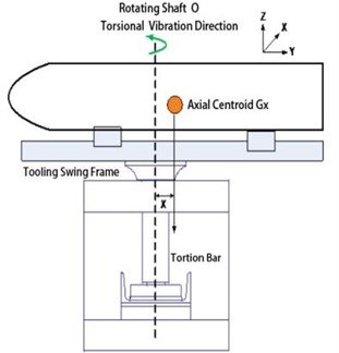
The rotational inertia measuring equipment is mainly composed of testing equipment matrix, testing equipment, pendulum, torsional vibration system unloading mechanism, release mechanism. In order to adapt to the measurement of inertia of the smaller rotating body, the fixture uses as much light material as possible, such as aluminum alloy. The rotational inertia measuring device is composed of a clamp, a screw rod, a releasing mechanism, a guide rail and a base. According to the law of rotation, the equation of motion of the tooling, the rotating shaft and the object to be tested is that:
In the formula: is the moment of inertia; is the torsion coefficient of spring; is the damping torque; is the angular displacement; is the moment of inertia of the torsion pendulum itself; is moment of inertia of objects to be measured; is the swing period of pallets and tested objects; ,
The system uses photoelectric sensor to complete cycle acquisition. In the signal processing, it is necessary to accurately measure the timing at which the timer starts to be measured. In the future, the circuit will be anti-jamming, and a leveling reference circuit with a certain threshold and a certain delay is used to expand the shaping circuit, but at this time, the timing start time is random. The error, in the same way, there must be a random error at the exact moment when the next counting pulse arrives. As a complete period of measurement, it is obviously impossible to characterize the period with the time between two pulses. In order to minimize the error, the number of cycles are measured as the measured values of the cycle according to the condition that the oscillation period is substantially constant. In the actual test, the initial external force disturbance is removed for several cycles, and each adjacent two-time segments is used as one cycle number, starting from the effective counting pulse, and each two counting pulses is one cycle data, and is removed by the total timing time. The complete number of cycles obtained in turn gives the period value at that moment.
3. Error analysis of moment of inertia
3.1. Measurement error analysis
Available from Eq. (3):
Available from Eq. (4), the relative error of the moment of inertia measurement is only twice the relative error of the time test and is very small.
3.2. Position error analysis
1. Influence of vertical axis displacement on rotational inertia of revolving body
Fig. 2Measuring shaft offset of moment of inertia
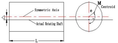
The influence of the rotation axis offset on the moment of inertia is as shown in Fig. 2. The eccentricity is , the deviation distance between the rotation axis and the projectile mandrel is , and the moment of inertia of the projectile to the mandrel axis is as follows:
The polar moment of inertia of the projectile on the axis of deviation is as follows:
Relative error of the moment of inertia (maximum):
Relative error is related to eccentricity.
3.3. Influence of the tilting of the rotating shaft on the moment of inertia of the pole and the equator
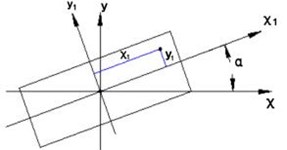
When the inclination angle (see Fig. 3) is applied to the rotation formula:
when 20, 0.5°, the influence of inclination angle on the relative error of polar moment of inertia is less than 210-3, and the influence on the equatorial moment of inertia is smaller. When the tilt and the offset of the shaft exist simultaneously, the result of the above analysis can be superimposed.
Fig. 3Schematic diagram of axis inclination
3.4. Influence of damping on the test result of moment of inertia
1. The measured moment of inertia of equator without damping.
The test process is shown in Fig. 4.
Fig. 4Undamped measurement moment of inertia
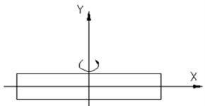
First, the swing period of the turntable is measured. (There is nothing left on the turntable). Then, the swing period of turntable and standard parts is measured. Last, the swing period of the turntable and the projectile and arrow to be measured is measured.
Three known numbers , and were measured, according to the relationship between vibration frequency and moment of inertia, three equations can be listed to solve three unknowns: empty table inertia , spring stiffness , moment of inertia for projectile to be measured :
2. The measured moment of inertia of equator with damping.
Assume that the swing resistance torque is proportional to the swing angle speed. The swing equation is as follows:
In the formula, is spring stiffness, and are damping coefficient and undamped frequency. When , the solution of differential equation is as follows:
Damping frequency:
Damping period:
By measuring damping oscillation period , the moment of inertia of projectile to be measured is calculated.
3.5. Accuracy analysis of moment of inertia measurement
and can be accurately measured beforehand in the calculation formula of moment of inertia. The main source of the error is the measurement error of the oscillating period , and there are two sources of the periodic error: one is the time measurement error, the other is the error caused by neglecting the damping torque. The influence of timing error on the measurement of inertia can be obtained by the following error analysis. The formula for calculating the moment of inertia is as follows:
Because the response frequency of the sensor is 1000 Hz and the response time is less than 1 ms, the precision of time measurement is high and the error of time measurement can be neglected. Assuming that is a damping period, the attenuation of vibration is exponential decay. According to the principle of torsional vibration:
As a result:
As a result:
It is known by , , :
Substituting the Eq. (15) into the Eq. (16):
The actual amplitude attenuation is much smaller than 0.7, so the impact on the actual test cycle is far less than 0.08 %, and the final measurement accuracy is not greatly affected. As mentioned above, the test accuracy of the moment of inertia can reach 0.1 %.
4. Conclusions
The test of moment of inertia is widely used in a wide range of applications and has broad application prospects. The moment of inertia test can verify whether the component or equipment meets the design requirements and can also provide raw data for its research design, attitude calculation, work result analysis and accuracy calculation, and also provide information for its structural optimization. In this paper, the method of torsion bar is used to measure the moment of inertia. By means of measuring error, position error and deviation concurrence. The influence of measurement error, position error and damping on measurement accuracy is very limited. By analyzing the measuring accuracy of rotational inertia of revolving body, the test accuracy of the moment of inertia can reach 0.1 % or more. The research results can provide technical support and theoretical guidance for the test of moment of inertia.
References
-
Wang Demin, Ma Yiping Typical moment of inertia measurement devices. Mechanical Research and Application, Vol. 27, Issue 6, 2014, p. 63-66.
-
Zhang Xinming, Zheng Yingjie, Chi Zhanduo Effect of centroidal deviation on measurement of rotational inertia of projectile body by torsion pendulum method. Acta Armamentarii, Vol. 34, Issue 6, 2013, p. 797-800.
-
Zhang Xinming, Wang Demin, Lin Junye, et al. Analysis of the influence of damping on moment of inertia based on compound pendulum measurement method. Journal of Changchun University of Science and Technology, Vol. 41, Issue 4, 2018, p. 54-59.
-
Bian Zhiqiang, Tang Zhengang, Li Shuangling, Xu Kai Research on integration testing method on rotational inertia and product of inertia for spacecraft. Aerospace Manufacturing Technology, Vol. 6, 2017, p. 16-20.
-
Zhang Xinming, Wang Lingyun, Liu Jianhe, Yang Jiandong Measurement of inertia moment and centroidal deviation of rocket projectile with compound pendulum method and its error analysis. Acta Armamentarii, Vol. 4, 2008, p. 450-453.
-
Li Huipeng, Tang Wenyan, Zhang Chunfu, Sun Heyi, Wang Jun A measuring system of inertia moment of missile and its error analysis. Acta Armamentarii, Vol. 2, 2007, p. 206-208.
-
Zhang Xinming, Wang Liming, Liu Jianhe, et al. Study on relation between dynamic imbalance degree and product of inertia. Journal of China Ordnance, Vol. 4, Issue 1, 2008, p. 65-68.
-
Wang Deming, Liu Jian, Sun Yingying The research of the double-torsion-bars device of measuring moment of inertia based on pendulum method. Mechanical Design and Research, Vol. 31, Issue 6, 2015, p. 81-86.
About this article

The authors would like to thank the Project of Education Department of Jilin Province No. JJKH20181127KJ.
