Abstract
Creep fracture of rock cracks is responsible for the creep failure of fractured rock masses. To capture creep fracture behaviors of fractured rock, we investigated the time-dependent characteristics of the rock crack propagation. The theoretical analysis shows that, similar to the rock creep process, the creep fracture of rock cracks includes the attenuation and steady creep stages. In addition, we established an equivalent Burgers model for creep fracture of rock cracks by introducing the equivalent stress and proposed a double Burgers model to study creep behaviors of fractured rock masses. Moreover, the proposed double Burgers model was embedding into FLAC3D, using FISH function. The numerical simulations on the specimens, containing ordered and random cracks, show that the creep fracture is responsible for the creep damage of fractured rock masses; moreover, the lateral creep damage is larger than the axial creep damage.
Highlights
- The creep fracture of rock cracks includes the attenuation and steady creep stages.
- A double Burgers model was proposed to study creep behaviors of fractured rock masses.
- The creep fracture of rock cracks is responsible for the creep damage of fractured rock masses.
1. Introduction
Extensive micro, meso and macro defects in rock masses may affect the failure pattern and stability of the rock masses, because the failure the rock masses frequently results from the creep expansion and coalescence of the original defects [1-4]. In addition, the mechanical property and the distribution significantly affect the failure pattern. Thus, the time-dependent characteristics of the rock masses, containing original defects, deserve detail investigations.
The loading history may affect the nonlinear creep of the rock mass. To study the failure mechanism of the fractured rock mass, the time-dependent crack propagation, namely the creep fracture, should be considered. Creep fracture (subcritical crack propagation) occurs, because cracks propagate at an extremely low speed when the long-term load is lower than a critical value [5, 6]. In addition, many factors, including the stress intensity factor, pressure, temperature, activity of the environmental medium may affect subcritical crack propagation.
Extensive experimental studies showed that the creep fracture is common. For instance, using the SEM method, Kranz [7] studied the creep fracture of the Barre granite when a load, being equal to 87 % of the fracture strength was applied, and further proposed that the increase in the loading time promotes the crack length and the crack number. Xiao et al. [8] investigated the dynamic crack propagation and coalescence of the micro cracks in the specimens in uniaxial compressive and tensile conditions. They found that the total deformation is equal to the medium deformation and the crack deformation, caused by crack sliding and propagation. Wu and Thomsen [9] investigated the micro crack propagation and the macro deformation of the Westerly granite under creep load and detected increasing acoustic emissions. In addition, they further proposed that the failure of the specimens results from the crack propagation and coalescence.
Previous studies mainly were focused on the macro creep response of the rock mass [10-12]. However, the crack creep propagation, especially the creep failure of rock masses induced by rock crack creep fracture, lacks sufficient investigations. External loads subsequently cause the cracks to open, slide, initiate, propagate, and then coalesce. Simultaneously, the crack distribution may significantly affect creep fracture with the accumulation of the creep damage. Therefore, the mechanical model of the creep fracture that can depict the failure mode and mechanism deserves detail investigations. In the present article, based on the rock fracture mechanics and creep mechanics, we proposed a method to calculate the inelastic damage deformation, caused by creep fracture. More importantly, we verified the feasibility of this method by embedding this method into FLAC3D. This method may shed some lights on the creep deformation mechanism of rock masses.
2. Theoretical basis
2.1. Crack initiation
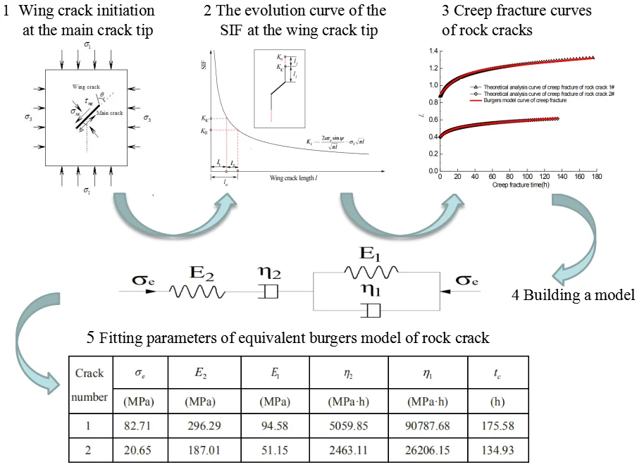
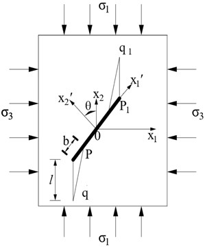
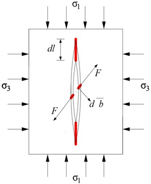
The normal and tangential stresses applied on the main crack surface in compressive-shear states yield (Fig. 1):
where and are normal and tangential stresses applied on the main crack surface, respectively, and are the maximum and minimum principal stresses, respectively, is the angle between the crack and the maximum principal stress.
According to the maximum circumferential stress theory, the initial crack propagates at the tip of main crack along the direction of the maximum circumferential stress, with a crack initiation angle of 70.5°. The stress intensity factor (SIF) at the main crack tip is [13]:
where is the friction coefficient of the crack surface, and is the half of crack length.
When the SIF at main crack tip is higher than the fracture toughness of rock,the wing crack initiates.
Fig. 1Schematic diagram of wing crack initiation at the main crack tip
2.2. Transient propagation of the wing crack
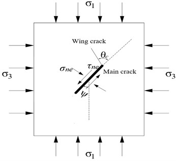
The previous experimental studies [1, 6-8] indicated that the wing crack propagates approximately along the direction of the maximum principle stress, after it initiates, as shown in Fig. 2.
Fig. 2Wing crack propagation
The influence of the main crack on the SIF of wing crack tip can be reflected by the effective shear stress applied on the main crack [13]:
According to Horri and Nemat-Nasser wing crack model [14], the SIF of the wing crack tip can be expressed:
where is the propagation length of wing crack, is the angle between the wing crack and the main crack.
The SIF at the wing crack tip continuously decreases with the wing crack propagation, according to Eq. (5). The crack transient propagation length can be obtained, by assuming that is in Eq. (5).
2.3. Creep propagation of wing crack
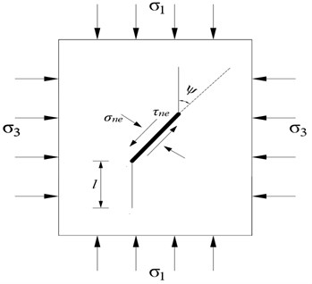
Previous experimental results [3, 5, 7, 15] showed that a subcritical crack growth at very low velocity (10-2-10-9 m/s) can be observed when the SIF is between the threshold stress intensity for subcritical crack growth and the fracture toughness [3, 5, 15-17], which is crack creep propagation. When is lower than , crack propagation ceases. The ultimate crack propagation length can be obtained, by assuming that equals in Eq. (5). The subcritical crack propagation length is a difference between the ultimate crack propagation length and crack transient propagation length (Fig. 3).
Experimental studies on the subcritical crack propagation showed that the rate of the creep fracture is [3, 5, 15-17]:
where, is an arbitrary value in range of subcritical propagation length, and are parameters related to subcritical crack propagation.
Eq. (6) shows that the crack propagation rate decreases with the increase in crack propagation length. When the SIF decreases to the threshold stress intensity for subcritical crack growth , the crack propagation ceases [15-17].
Fig. 3The evolution curve of the SIF at the wing crack tip
3. Equivalent Burgers model for crack creep fracture
Cracks in compressive-shear states are very common in rock engineering. Thus, the time-dependent stability of these cracks is significant. Eq. (5) can be rewritten:
when, can be further obtained:
where and are and , respectively.
The whole duration of subcritical crack propagation can be expressed according to Eq. (8):
with Eqs. (8) and (9), the crack propagation length can be calculated.
Using the above theoretical model to analyze the creep fracture characteristics, two cracks, Crack #1 and Crack #2, with different occurrences, are adopted. The computational parameters were: for Crack #1, 0.21 m, 45°; and 0.25, for Crack #2, 0.10 m, 20°; and, and the maximum and minimum principle stresses were 35.0 MPa and 1.65 MPa, respectively. According to the previous study [18], the parameters of the rock sample are listed in Table 1. In addition, Fig. 4 shows the calculation element of the creep fracture.
Table 1Calculation parameters of subcritical crack propagation of marble
Lithology | (MPam0.5) | (MPam0.5) | Subcritical crack propagation parameters | |
Marble | 3.4328 | 2.40 | 5.98×10-17.2 | 12.58 |
Fig. 4The calculation unit for wing crack
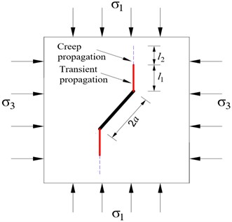
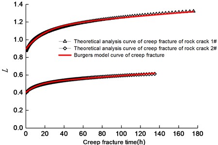
Fig. 5 shows the creep fracture curves of crack propagation for Cracks #1 and 2. For simplification, the dimensionless propagation length was used. Clearly, the crack propagation length increases with the increase in creep time. Similar to typical rock creep, the creep fracture of rock crack includes the attenuation and steady creep stages, characterized by the decreasing and constant propagation rates, respectively. When the SIF at the wing crack tip is lower than , or the crack coalesces with other cracks, the crack propagation ceases.
The creep fracture characteristics may vary for various cracks with different occurrences. For Crack #1 and Crack #2, the transient dimensionless lengths were 0.87 and 0.40, and the dimensionless creep lengths were 0.45 and 0.21 respectively. Moreover, the whole duration of crack creep propagation for Crack #1 and Crack #2 are 175.61 h and 134.93 h, respectively. The creep fracture time for Crack #1 is higher due to the relatively longer propagation length for crack #1 (see Fig. 5).
Fig. 5Creep fracture curves of rock cracks
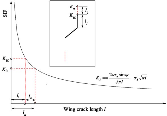
Eq. (6) shows that the SIF increases with the increase in the effective shear stress , whereas decreases with the increase in the minimum principle stress . To establish the equivalent Burgers model for the creep fracture, we introduced the equivalent stress :
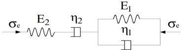
The proposed equivalent Burgers model is shown in Fig. 6. The crack transient propagation can be described by a Hooke body. The crack creep propagation is described by the connection between a Newton body and a Kelvin body in series. The equivalent Burgers model for creep fracture is:
where is termination time of crack creep propagation, is the dimensionless crack propagation length,is the time to subcritical crack propagation, , , and are model parameters, respectively.
Fig. 6Equivalent Burgers model for creep fracture of rock crack
The creep fracture curves of rock cracks are fitted by using the proposed equivalent Burgers model. Table 2 summarizes the model parameters of Cracks #1 and 2. From Fig. 5, it is found that the equivalent Burgers model curves agree very well with the theoretical curves. The proposed equivalent Burgers model is proper to describe of the creep fracture process of rock cracks.
Table 2Fitting parameters of equivalent burgers model of rock crack
Crack number | (MPa) | (MPa) | (MPa) | (MPa·h) | (MPa·h) | (h) |
1 | 82.71 | 296.29 | 94.58 | 5059.85 | 90787.68 | 175.58 |
2 | 20.65 | 187.01 | 51.15 | 2463.11 | 26206.15 | 134.93 |
4. Double Burgers model for fractured rock masses
The creep deformation of the fractured rock masses composes of the creep deformations of the rock matrix and the rock cracks. Thus, to investigate the macro creep damage of the fractured rock masses, in the present study, the proposed equivalent Burgers model for creep fracture of rock cracks is integrated with the Burgers model of rock matrix to describe creep behavior of fractured rock masses.
4.1. Damage deformation caused by crack creep fracture
The strain increment of the fractured rock masses, , composes of the strain increment of rock matrix, and the damage strain increment of the cracks, :
The increment of the linear elastic strain of the rock matrix is:
where is elastic flexibility tensor for rock matrix.
The damage strain increment, caused by crack slippage and propagation, can be obtained, using the Rice thermodynamic theory [19, 20]:
where is a set of thermodynamic forces conjugated to the internal variables , the is the stress tensor, is the present condition of the internal variable, and denotes the volume of a representative volume element (RVE).
The average slip of the points on is equal to the average Mode II crack opening displacement induced by the effective shear stress (see Fig. 7(a)):
where, is the Passion ratio, is the elastic modulus.
The increment of inelastic strain induced by crack slippage can be expressed [19, 20]:
where, is the initial crack density parameter, is the number of (non-interacting) cracks having the same orientation , is the area of the representative unit, , a normalized slip, is the angle between the two coordinate systems 2.
Then, Fig. 7 shows the increment of the nonlinear damage strain, caused by wing crack propagation. According to the equilibrium conditions of the plane and the Mohr-Coulomb criterion, the balanced force on the main crack plane is:
The average opening of the mode II crack, induced by , due to wing crack propagation is:
Fig. 7a) Model of wing crack in compressive-shear state, b) increment of the inelastic damage strain induced by wing crack propagation
a)
b)
The inelastic residual energy, generated by wing crack propagation is [20]:
where:
The increment of the inelastic residual energy can be expressed as [20]:
So, a set of thermodynamic forces conjugated to the internal variables and can be expressed as:
The increment of the nonlinear damage strain is:
According to Eq. (24), the increment of the nonlinear damage strain, caused by wing crack propagation can be obtained. Thus, the damage deformation is time-dependent due to creep propagation of wing crack[21, 22].
4.2. Double Burgers model
The Burgers creep model of rock matrix includes the Kelvin model and the Maxwell model, thus, the corresponding constitutive model, in the form of stress and strain deviation, yields [10-12]:
where, , , and are the elastic modulus of controlling delay, the elastic shear modulus, the rate of determining the delayed elasticity and the viscous flow rate, respectively.
The stress tensor at a certain point can be decomposed into the deviatoric stress tensor () and the spherical stress tensor (). Similarly, the strain tensor at a certain point can be decomposed into the deviatoric strain tensor () and the spherical strain tensor (). These parameters have a specific relationship under an elastic state, which can be expressed as follows:
The following assumptions are made (Ottosen 1986): (1) creep is sensitive to deviatoric stress tensor (), but the spherical stress tensor () does not cause the creep; (2) the Poisson’s ratio of the rock does not change over time in the process of creep. Based on the above assumptions, the Burgers model yields:
Double Burgers model of fractured rock masses is proposed in order to study the creep behaviors of fractured rock masses [23]. The implementation steps are as follows: (1) Determine creep parameters of the rock matrix based on Burgers creep model; (2) Determine creep propagation length of rock cracks based on equivalent Burgers model for crack creep fracture; (3) Determine the inelastic damage strain, caused by creep fracture of rock cracks; (4) Determine whole creep strain of fractured rock masses according to Eq. (12). To implement the numerical simulation of double Burgers model of fractured rock masses, the inelastic damage deformation caused by crack creep fracture is embedded into the Burgers model in FLAC3D.
5. Case study
Numerical simulations on the specimens, containing ordered and random fractures were performed to investigate the creep characteristics of fractured rock masses.
5.1. Numerical results of the specimen containing ordered cracks
Fractured rock specimen with a height of 2.0 m and a width of 1.0 m has two sets of ordered cracks [24, 25]. Table 3 shows the distribution parameters of the original cracks. According to the previous study [16], the creep parameters of rock matrix are shown in Table 4. The parameters for subcritical crack propagation and equivalent burgers model of marble crack are listed in Tables 1 and 2, respectively. The maximum and minimum principle stresses applied on specimens are set to 35 MPa and 1.65 MPa, respectively.
Table 3Structural parameters of ordered rock crack groups
Crack group number | Dip angle (°) | Trace length (m) | Spacing (m) | Break distance (m) | Initial crack density parameter | Friction coefficient |
1 | 45 | 0.42 | 0.35 | 0.40 | 10.50 | 0.25 |
2 | 20 | 0.35 | 0.50 | 0.36 | 9.00 | 0.15 |
Table 4Burgers model parameters of marble
Lithology | (GPa) | (GPa) | (GPa·h) | (GPa·h) |
Marble | 2.869 | 1.388 | 6.598 | 2769.28 |
The inelastic damage strain, caused by creep fracture of rock cracks is calculated according to Eq. (24). The axial and lateral inelastic damage strains are plotted in Fig. 8, where the lateral damage strain is much higher than the axial damage strain. For example, the lateral damage strain is 2.68 times of the axial damage strain at creep time of 176 h, because the contribution of wing propagation to lateral damage strain is larger than axial damage strain [26].
Figs. 9(a) and (b) show the comparisons of creep curves of fractured rock specimen with and without consideration of creep damage, respectively. It is noted that both the lateral and axial creep strains with consideration of creep damage are higher than those without consideration of creep damage. Especially, the lateral creep strain with consideration of creep damage is much higher than that without consideration of creep damage. For example, the lateral creep strain when creep damage is considered is 1.48 times of this when creep damage is ignored at creep time of 176 h. The creep ratio at steady creep stage with and without consideration of creep damage is 7.18×10⁻⁹ h-1 and 4.33 h-1, the former is 1.66 times of the latter.
Fig. 8Inelastic damage strain curves of ordered rock cracks group
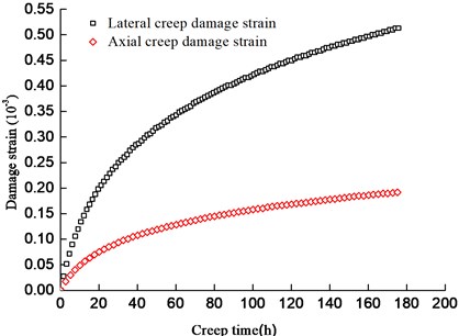
Fig. 9Comparisons of creep curves of fractured rock specimen with and without consideration of creep damage for: a) lateral creep strain, b) axial creep strain
a)
b)
5.2. Numerical results of the specimens containing random cracks
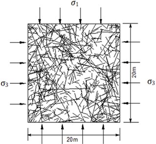
Fractured rock specimens containing random cracks is a square with a height of 20 m and a width of 20 m as shown in Fig. 10. The distribution parameters of the random cracks are listed in Table 5.
Fig. 10Fractured rock specimens containing random cracks
The creep damage strain-time curve of the fractured rock masses is plotted in Fig. 11. The axial and lateral creep damage strains nonlinearly increase with the increase in creep time. The lateral damage strain is much higher than the axial damage strain. The lateral damage strain is 3.46 times of the axial damage strain at creep time of 200 h.
Table 5The distribution parameters of the random crack
Joint | Dip angle (°) | Trace length (m) | Break distance (m) | Spacing (m) | Gap width (m) | ||
Normal distribution | Negative exponential distribution | Uniform distribution | Negative exponential distribution | Negative exponential distribution | |||
Avg. | Sd. | Avg. | Avg. | Sd. | Avg. | Ave. | |
1 | 67.0 | 8.5 | 2.21 | 0.68 | 0.18 | 1.25 | 0.1 |
2 | 115.2 | 6.1 | 1.75 | 1.12 | 0.24 | 1.16 | 0.3 |
3 | 35.1 | 1.3 | 1.89 | 0.87 | 0.56 | 1.08 | 0.4 |
Note: Avg. is average value, and Sd. is standard deviation | |||||||
Fig. 11The creep damage strain-time curve of the fractured rock masses
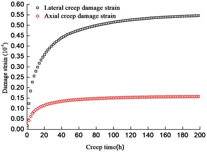
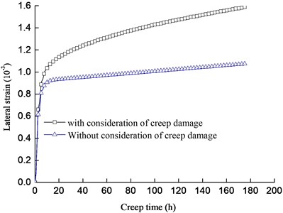
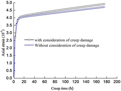
Fig. 12 shows the creep curves of fractures rock masses, when creep damage is considered and ignored. It is noted the crack creep fracture significantly contributes to the lateral creep damage, so the lateral creep strain with consideration of creep damage is much higher than that without consideration of creep damage, however, the contribution of crack creep fracture to the lateral creep strain relatively is smaller.
Fig. 12Comparisons of creep curves with and without consideration of creep damage
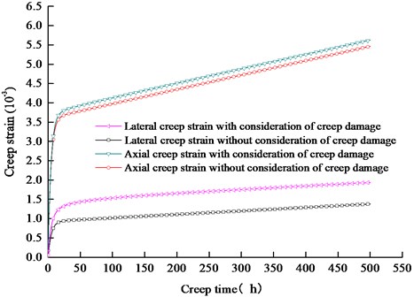
For example, the lateral and axial creep strains when creep damage is considered are 1.40 and 1.03 times of those when creep damage is ignored at creep time of 200 h, respectively. The above rules for fractured rock specimens containing random cracks are the same to fractured rock specimens containing random cracks.
6. Conclusions
Creep fracture of rock cracks is responsible for the creep failure of fractured rock masses. To investigate the macro creep damage of the fractured rock masses, the equivalent Burgers model for creep fracture of rock cracks is integrated with the Burgers model of rock matrix to describe creep behaviors of fractured rock masses. The following conclusions are obtained:
1) Similar to the rock creep process, the creep fracture of rock cracks includes the attenuation and steady creep stages. An equivalent Burgers model for rock crack creep fracture is proposed, based on the introduction of an equivalent stress.
2) The creep deformation of the fractured rock masses composes of the creep deformations of the rock matrix and the rock cracks, moreover, the contribution of crack creep fracture to the creep strain can be considered as creep damage strains.
3) The equivalent Burgers model for creep fracture of rock cracks is integrated with the Burgers model of rock matrix. The double Burgers creep model for fractured rock masses is proposed to describe creep behaviors of fractured rock masses.
4) The lateral creep strain with consideration of creep damage is much higher than that without consideration of creep damage, however, the contribution of crack creep fracture to the axial creep strain relatively is smaller.
References
-
Zhao Y., Zhang L., Wang W., Pu C., Wen W., Tang J. Cracking and stress-strain behavior of rock-like material containing two flaws under uniaxial compression. Rock Mechanics and Rock Engineering, Vol. 49, 2016, p. 2665-2687.
-
Wang Y. X., Guo P. P., Ren W. X., Yuan B. X. Laboratory investigation on strength characteristics of expansive soil treated with jute fiber reinforcement. International Journal of Geomechanics, Vol. 17, 2017, p. 04017101.
-
Kaneko K., Koike K., Yoneda T., Nara Y. Relation between subcritical crack growth behavior and crack path in granite. International Journal of Rock Mechanics and Mining Sciences, Vol. 43, 2006, p. 1256-126.
-
Wang Y. X., Guo P. P., Dai F., Li X., Zhao Y. L., Liu Y. Behavior and modeling of fiber-reinforced clay under triaxial compression by combining the superposition method with the energy-based homogenization technique. International Journal of Geomechanics, Vol. 18, 2018, p. 04018172.
-
Dill S. J., Bennison S. J., Dauskardt R. H. Subcritical crack growth behaviour of borosilicate glass under cyclic loads: evidence of a mechanical fatigue effect. Journal of the American Ceramic Society, Vol. 60, 1977, p. 773-776.
-
Zhao Y., Luo S., Wang Y., Wang W., Zhang L., Wan W. Numerical analysis of karst water inrush and a criterion for establishing the width of water-resistant rock pillars. Mine Water and the Environment, Vol. 36, 2017, p. 508-519.
-
Kranz R. L. Crack growth and development during creep of barre granite. International Journal of Rock Mechanics and Mining Sciences, Vol. 16, 1979, p. 23-35.
-
Xiao H. T., Zhou W. Y., Yang R. Q. Macroscopic analysis of rheological growth of rock cracks. Chinese Journal of Rock Mechanics and Engineering, Vol. 8, 1999, p. 623-626.
-
Wu F. L., Thomsen L. Micro-fracturing and deformation of westerly granite under creep condition. International Journal of Rock Mechanics and Mining Sciences, Vol. 2, 1975, p. 167-173.
-
Zhao Y. L., Zhang L. Y., Wang W. J., Wan W., Ma W. Separation of elastoviscoplastic strains of rock and a nonlinear creep model. International Journal of Geomechanics, Vol. 18, 2018, p. 04017129.
-
Zhao Y. L., Zhang L. Y., Wang W. J., Wan W., Li S. Q., Ma W. H., Wang Y. X. Creep behavior of intact and cracked limestone under multi-level loading and unloading cycles. Rock Mechanics and Rock Engineering, Vol. 50, 2017, p. 1409-1424.
-
Zhao Y., Wang Y., Wang W., Wan W., Tang J. Modeling of non-linear rheological behavior of hard rock using triaxial rheological experiment. International Journal of Rock Mechanics and Mining Sciences, Vol. 93, 2017, p. 66-75.
-
Ashby M. F., Hallam S. D. The failure of brittle solids containing small cracks under compressive stress states. Acta Metallurgica, Vol. 34, 1986, p. 497-510.
-
Horri H., Nemat-Nasswer S. Brittle failure in compression: splitting, faulting and brittle-ductile transition. Philosophical Transactions of the Royal Society A, Vol. 139, 1986, p. 337-374.
-
Nara Y., Takada M., Igarashi T., Hiroyoshi N. Kaneko Subcritical crack growth in rocks in an aqueous environment. Exploration Geophysics, Vol. 40, 2009, p. 163-171.
-
Nara Y., Tanaka M., Harui T. Evaluating long-term strength of rock under changing environments from air to water. Engineering Fracture Mechanics, Vol. 178, 2017, p. 201-211.
-
Ko T., Kemeny J. Determination of the subcritical crack growth parameters in rocks using the constant stress-rate test. International Journal of Rock Mechanics and Mining Sciences, Vol. 59, 2013, p. 166-178.
-
Yuan H. P. Study on the Rheological Fracture of Jointed Rock Mass under Inducing Condition and Its Engineering. Central South University, Changsha, 2006.
-
Rice J. R. Inelastic constitutive relations for solids: an internal-variable theory and its application to metal plasticity. Journal of the Mechanics and Physics of Solids, Vol. 19, 1971, p. 433-455.
-
Basistat M., Gross D. The sliding crack model of brittle deformation: an internal variable approach. International Journal of Solids Structures, Vol. 35, 1988, p. 487-509.
-
Wang Y., Wang S., Zhao Y., Guo P., Liu Y., Cao P. Blast induced crack propagation and damage accumulation in rock mass containing initial damage. Shock and Vibration, Vol. 2018, 2018, p. 10-22.
-
Zhao Y., Zhang L., Wang W., Tang J., Lin H., Wan W. Transient pulse test and morphological analysis of single rock fractures. International Journal of Rock Mechanics and Mining Sciences, Vol. 91, 2017, p. 139-154.
-
Hou R., Zhang K., Tao J., Xue X., Chen Y. A Nonlinear creep damage coupled model for rock considering the effect of initial damage. Rock Mechanics and Rock Engineering, Vol. 92, 2018, p. 1-11.
-
Yang S., Huang Y., Tian W., Zhu J. An experimental investigation on strength, deformation and crack evolution behavior of sandstone containing two oval flaws under uniaxial compression. Engineering Geology, Vol. 30, 2017, p. 35-48.
-
Cao P., Liu T., Pu C. Crack propagation and coalescence of brittle rock-like specimens with pre-existing cracks in compression. Engineering Geology, Vol. 187, 2015, p. 113-121.
-
Zhao Y., Wang Y., Wang W., Tang L., Liu Q., Cheng G. Modeling of rheological fracture behavior of rock cracks subjected to hydraulic pressure and far field stresses modeling of rheological fracture behavior of rock cracks subjected to hydraulic pressure and far field stresses. Theoretical and Applied Fracture Mechanics, Vol. 101, 2019, p. 59-66.
Cited by
About this article

This research was supported by the National Natural Science Foundation of China (51774131, 51274097, 51434006) and the CRSRI Open Research Program (CKWV2017508/KY).
